tire pressure MITSUBISHI OUTLANDER SPORT 2014 3.G Owners Manual
[x] Cancel search | Manufacturer: MITSUBISHI, Model Year: 2014, Model line: OUTLANDER SPORT, Model: MITSUBISHI OUTLANDER SPORT 2014 3.GPages: 384, PDF Size: 46.94 MB
Page 9 of 384
Outside 1-7 Overview
1
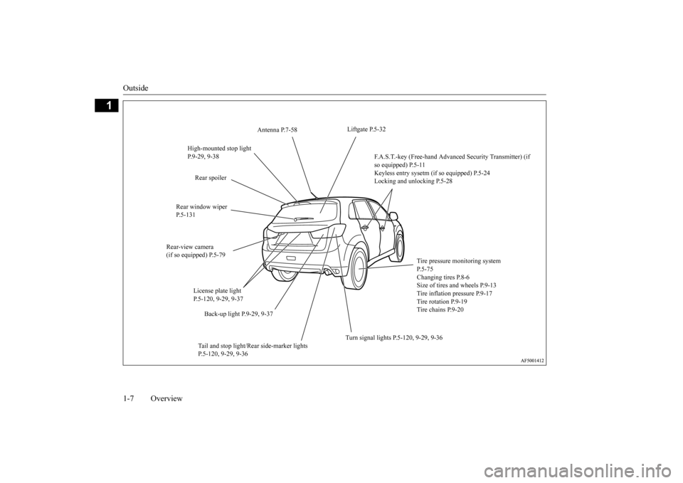
Liftgate P.5-32
Antenna P.7-58
High-mounted stop light P.9-29, 9-38
F.A.S.T.-key (Free-hand Advanced Security Transmitter) (if so equipped) P.5-11 Keyless entry sysetm (if so equipped) P.5-24Locking and unlocking P.5-28
Rear spoiler
Rear window wiper P.5-131
Rear-view camera (if so equipped) P.5-79
Tire pressure monitoring system P.5-75Changing tires P.8-6 Size of tires and wheels P.9-13 Tire inflation pressure P.9-17 Tire rotation P.9-19 Tire chains P.9-20
License plate light P.5-120, 9-29, 9-37
Back-up light P.9-29, 9-37
Turn signal lights P.5-120, 9-29, 9-36
Tail and stop light/Rear side-marker lights P.5-120, 9-29, 9-36
BK0202700US.bo
ok 7 ページ 2013年3月28日 木曜日 午前11時54分
Page 11 of 384
If this warning light comes on or
flashes while you’re driving...
2-2 Quick index
2
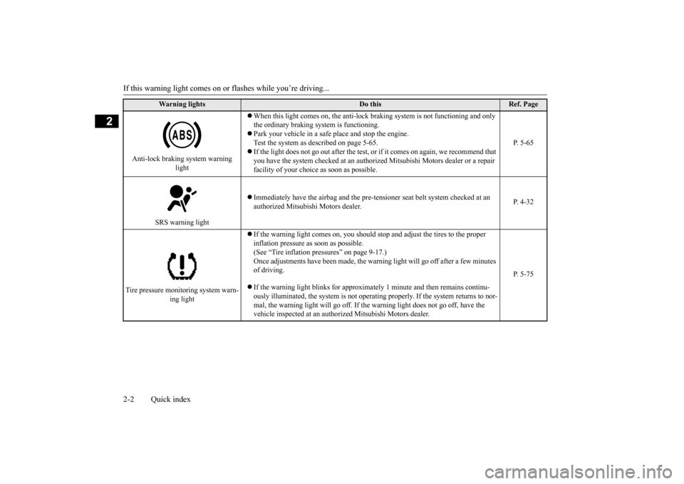
Anti-lock braking system warning
light
When this light comes on, the anti-lock braking system is not functioning and only the ordinary braking system is functioning. Park your vehicle in a safe place and stop the engine. Test the system as described on page 5-65. If the light does not go out after the test, or if it comes on again, we recommend that you have the system checked at an authorized Mitsubishi Motors dealer or a repair facility of your choice as soon as possible.
P. 5-65
SRS warning light
Immediately have the airbag and the pre-te
nsioner seat belt system checked at an
authorized Mitsubishi Motors dealer.
P. 4-32
Tire pressure monitoring system warn-
ing light
If the warning light comes on, you should stop and adjust the tires to the proper inflation pressure as soon as possible. (See “Tire inflation pressures” on page 9-17.)Once adjustments have been made, the warnin
g light will go off after a few minutes
of driving. If the warning light blinks for approxim
ately 1 minute and then remains continu-
ously illuminated, the system is not operatin
g properly. If the system returns to nor-
mal, the warning light will go off. If the warning light does not go off, have the vehicle inspected at an authori
zed Mitsubishi Motors dealer.
P. 5-75
Warning lights
Do this
Ref. Page
BK0202700US.bo
ok 2 ページ 2013年3月28日 木曜日 午前11時54分
Page 64 of 384
5
Features and controlsBreak-in recommendation
s ...............................................................5-3
Keys .....................................................
.............................................5-3
Electronic immobilizer (Anti-theft starting system) .........................5-4 Keyless entry system (if so equipped) ..............................................5-7Free-hand Advanced Security Tran
smitter (F.A.S.T.-key) (if so
equipped)................................
..................................................... 5-11
Door locks........................
...............................................................5-28
Power door locks .............
...............................................................5-30
Child safety locks for r
ear door ....................
..................................5-31
Liftgate.......................................
.....................................................5-32
Inside liftgate releas
e ..............................................
........................5-33
Theft-alarm system ..........
...............................................................5-33
Power window control
............................................
........................5-36
Sunshade (if so equi
pped)..............................................................5-39
Parking brake ...................
...............................................................5-40
Steering wheel height and reach adjustment...................................5-41Inside rearview mirro
r ............................................
........................5-41
Outside rearview mirr
ors ................................................................5-43
Ignition switch .................
...............................................................5-44
Starting the engine .
.................................................
........................5-45
Manual transaxle (if so equipped) .................................................5-47 Continuously variable transmission
(CVT) (if so equipped).........5-49
Electronically controlled 4WD system (if so equipped)................5-554-wheel drive operation
..........................................
........................5-58
Inspection and maintenance following rough road operation.........5-60 Cautions on the handling of 4-wheel drive vehicles.......................5-60Service brake ...................
...............................................................5-61
Hill start assist........
.................................................
........................5-62
Brake assist system
................................................
......................... 5-64
Anti-lock braking syst
em ......................................
......................... 5-64
Electric power steering syst
em (EPS) ........................................... 5-66
Active stability control
(ASC) .....................
................................... 5-67
Cruise control (if so eq
uipped) ....................................................... 5-70
Tire pressure monitoring
system .................................................... 5-75
Rear-view camera (if so
equipped)..............
................................... 5-79
Instrument cluster .
.................................................
......................... 5-81
Multi-information disp
lay .....................................
......................... 5-82
Indicator light, warning light, and information screen display list
.................................................................
................................. 5-104
Indicators ..................................
.................................................... 5-116
Warning lights...........................
.................................................... 5-117
Information screen disp
lay .......................................................... 5-118
Combination headlights and dimmer switch ............................... 5-120 Headlight leveling switch (if so equipped).................................. 5-125Turn signal lever ...
.................................................
....................... 5-126
Hazard warning flasher
switch ..................................................... 5-127
Front fog light switch (if
so equipped) ........................................ 5-127
Wiper and washer swit
ch ......................................
....................... 5-127
Electric rear window def
ogger switch .......................................... 5-132
Horn switch ..............................
.................................................... 5-133
Link System (if so equi
pped) .....................
................................. 5-133
Bluetooth
® 2.0 interface (if so
equipped)..................................... 5-134
USB input terminal (if so
equipped) ........................................... 5-155
Sun visors .................................
.................................................... 5-158
12 V power outlets..........
.................................................
............. 5-159
Interior lights ..................
.................................................
............. 5-159
BK0202700US.bo
ok 1 ページ 2013年3月28日 木曜日 午前11時54分
Page 122 of 384
4-wheel drive operation
Features and controls 5-59
5
applied. This is called tight corner braking and results from each of the four tires being at a different distance from the corner. The phe- nomenon is typical of 4-wheel drive vehicles.If this occurs, either straighten out the steer- ing wheel or change to another mode. Set the drive mode-selector to “4WD AUTO”, “4WD LOCK” or “SNOW” in accordance with the road conditions, and then gradually depress the accelerator pedal for asmooth start.
Set the drive mode-selector to “4WD LOCK” or “LOCK” and then gradually depress the accelerator pedal for a smooth start. Keep the pressure on the accelerator pedal as constantas possible, and drive at low speed.
Your vehicle may not provide sufficient hill climbing ability and engine braking on steepslope. Avoid driving on
steep slopes even
On snowy or icy roads
NOTE
The use of snow tires is recommended. Maintain a safe distance between vehicles, avoid sudden braking, and use engine brak-ing (downshifting).CAUTION Avoid sudden braking, sudden acceleration and sharp turning. Skidding occurs and con- trol of the vehicle could be lost.
Driving on sandy or muddy roads
CAUTION Do not force the vehicle or drive recklessly on sandy surfaces. In comparison with nor- mal road surfaces, the engine and otherdrive-system components are put under excessive strain when driving on such a sur- face. This could lead to accidents. If any of the following conditions occur while the vehicle is being driven, immedi-ately park your vehicle in a safe place and follow these procedures:• If the engine coolant temperature display
flashes on the information screen in the multi-information display or the engine power drops suddenly. Refer to “Engine overheating” on page 8-4.• If the “ ” warning display and “SLOW DOWN” or the “ ” warning display and “SERVICE REQUIRED” appear on the information screen in the multi-information display.Refer to “Warning display” on page 5-51.
WA R N I N G When attempting to rock your vehicle out of a stuck position, be sure that the area around the vehicle is clear of people and physical objects. The rocking motion may cause the vehicle to suddenly launch for-ward/backward, causing injury or dam- age to nearby people or objects.NOTE
Avoid sudden braking, sudden acceleration and sharp turning; such operations could result in the vehicle becoming stuck. If the vehicle becomes stuck in sandy or muddy roads, it can often be moved with a rocking motion. Move the gearshift leveralternately between the 1st and “R” (Reverse) positions (M/T), the “D” (DRIVE) and “R” (REVERSE) positions (CVT), whilepressing lightly on the accelerator pedal. Driving on rough road can cause rust on the vehicle; wash the vehicle thoroughly as soon as possible after such use.
Climbing/descending sharp grades
BK0202700US.bo
ok 59 ページ 2013年3月28日 木曜日 午前11時54分
Page 124 of 384
Service brake
Features and controls 5-61
5
Be sure all four tires and wheels are the same size and type. When it is necessary to replace any of the tires or wheels, replace all four. All tires should be rotated before the wear difference between the front and rear tires is recognizable.
Good vehicle performance cannot be expected if there is a difference in wear between tires. Refer to “Tire rotation” on page 9-19. Check the tire inflation pressure regularly.
N00517500275
Overuse of the brake can cause weakening, resulting in poor brake response and prema- ture wear of the brake pads.When driving down a long or steep hill, use engine braking by downshifting.
CAUTION Always use tires of the same size, type, and brand that have no wear differences. Usingtires of different size, type, brands or degree of wear, will increase the differential oil tem- perature and result in possible damage to thedriving system. Further, the drive train will be subject to excessive loading, possibly leading to oil leakage, component seizure, orother serious failures.
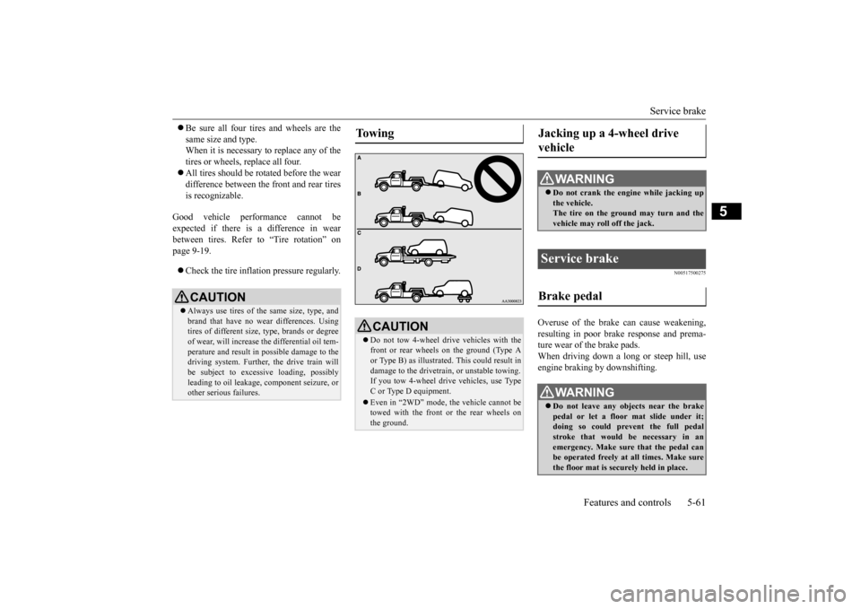
To w i n g
CAUTION Do not tow 4-wheel drive vehicles with the front or rear wheels on the ground (Type Aor Type B) as illustrated. This could result in damage to the drivetrain, or unstable towing. If you tow 4-wheel dr
ive vehicles, use Type
C or Type D equipment. Even in “2WD” mode, the vehicle cannot be towed with the front or the rear wheels on the ground.
Jacking up a 4-wheel drive vehicle
WA R N I N G Do not crank the engine while jacking up the vehicle.The tire on the ground may turn and the vehicle may roll off the jack.
Service brake Brake pedal
WA R N I N G Do not leave any objects near the brake pedal or let a floor mat slide under it; doing so could prevent the full pedal stroke that would be necessary in anemergency. Make sure that the pedal can be operated freely at all times. Make sure the floor mat is securely held in place.
BK0202700US.bo
ok 61 ページ 2013年3月28日 木曜日 午前11時54分
Page 138 of 384
![MITSUBISHI OUTLANDER SPORT 2014 3.G Owners Manual Tire pressure monitoring system
Features and controls 5-75
5
[Except for vehicles equipped with the F. A . S . T. - k e y ] Turn the ignition switch to the “OFF” or “ACC” position.[Vehic MITSUBISHI OUTLANDER SPORT 2014 3.G Owners Manual Tire pressure monitoring system
Features and controls 5-75
5
[Except for vehicles equipped with the F. A . S . T. - k e y ] Turn the ignition switch to the “OFF” or “ACC” position.[Vehic](/img/19/7547/w960_7547-137.png)
Tire pressure monitoring system
Features and controls 5-75
5
[Except for vehicles equipped with the F. A . S . T. - k e y ] Turn the ignition switch to the “OFF” or “ACC” position.[Vehicles equipped with the F.A.S.T.-key] Put the operation mode in OFF or ACC. “CRUISE” indicator light is turned OFF.
N00530201524
The tire pressure monitoring system uses tire inflation pressure sensors (A) on the wheels to monitor the tire infl
ation pressures. The
system only indicates when a tire is signifi- cantly under-inflated.
N00532700281
When the ignition switch is turned to the“ON” position or the operation mode is put in ON, the tire pressure monitoring system
Tire pressure monitoring system
WA R N I N G The compact spare wheel does not have a tire inflation pressure sensor. When the spare tire is used, the tire pres- sure monitoring system will not work properly.See an authorized Mitsubishi Motors dealer as soon as possible to replace or repair the original tire.NOTE
The tire pressure monitoring system is not a substitute for regularly checking tire infla- tion pressures.Be sure to check the tire inflation pressures as described in “Tires” on page 9-13. The tire inflation pressure sensor (A) is installed in the illustrated location. • On vehicles with Type 1 sensor which has the metallic air valve (B), replace grommet and washer (C) with a new one when thetire is replaced. • On vehicles with Type 2 sensor which has the rubber air valve (D), replace rubber air valve (D) with a new one when the tire is replaced.
For details, please contact your authorized Mitsubishi Motors dealer.
The tire pressure monitoring system warning light / display
NOTE
Type 1Type 2
BK0202700US.bo
ok 75 ページ 2013年3月28日 木曜日 午前11時54分
Page 139 of 384
Tire pressure monitoring system 5-76 Features and controls
5
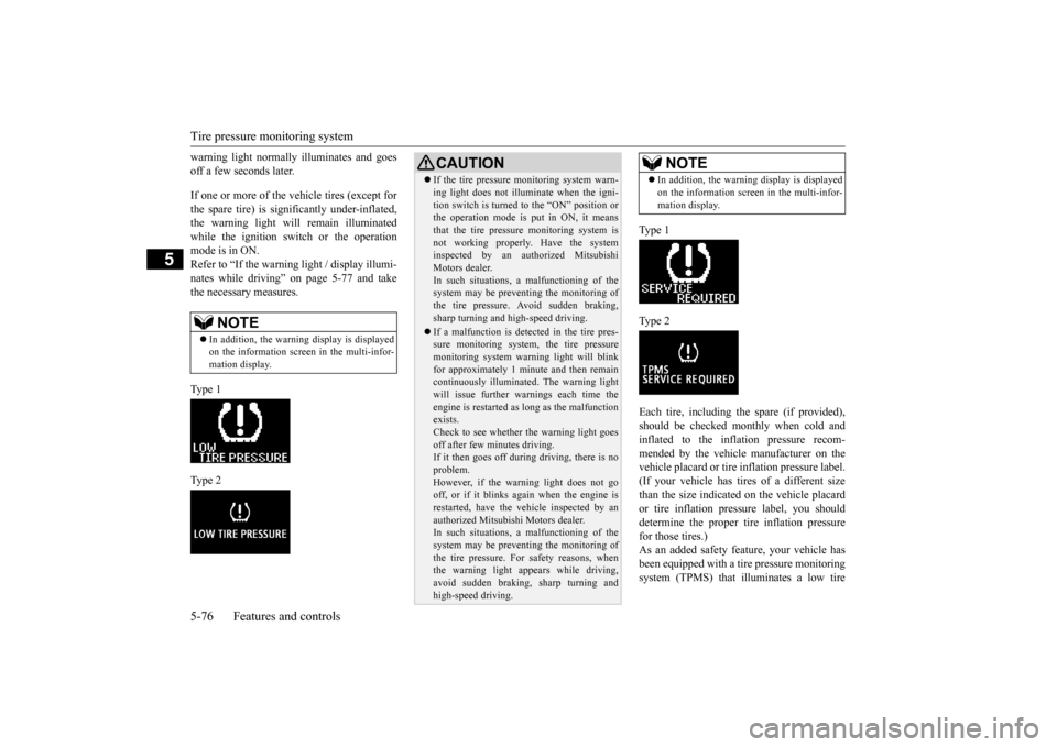
warning light normally illuminates and goes off a few seconds later. If one or more of the vehicle tires (except for the spare tire) is significantly under-inflated, the warning light will remain illuminatedwhile the ignition switch or the operation mode is in ON. Refer to “If the warnin
g light / display illumi-
nates while driving” on page 5-77 and take the necessary measures. Ty p e 1 Ty p e 2
Ty p e 1 Ty p e 2Each tire, including the spare (if provided), should be checked monthly when cold and inflated to the inflation pressure recom-mended by the vehicle manufacturer on the vehicle placard or tire inflation pressure label. (If your vehicle has tires of a different sizethan the size indicated on the vehicle placard or tire inflation pressure label, you should determine the proper tire inflation pressurefor those tires.) As an added safety feature, your vehicle has been equipped with a tire pressure monitoringsystem (TPMS) that illuminates a low tire
NOTE
In addition, the warning display is displayed on the information screen in the multi-infor- mation display.
CAUTION If the tire pressure monitoring system warn- ing light does not illuminate when the igni- tion switch is turned to the “ON” position or the operation mode is put in ON, it means that the tire pressure monitoring system isnot working properly. Have the system inspected by an authorized Mitsubishi Motors dealer.In such situations, a malfunctioning of the system may be preventing the monitoring of the tire pressure. Avoid sudden braking,sharp turning and high-speed driving. If a malfunction is detected in the tire pres- sure monitoring system, the tire pressure monitoring system warning light will blink for approximately 1 minute and then remaincontinuously illuminated. The warning light will issue further warnings each time the engine is restarted as long as the malfunctionexists. Check to see whether the warning light goes off after few minutes driving.If it then goes off during driving, there is no problem. However, if the warning light does not gooff, or if it blinks again when the engine is restarted, have the vehicle inspected by an authorized Mitsubishi Motors dealer. In such situations, a malfunctioning of the system may be preventing the monitoring ofthe tire pressure. For safety reasons, when the warning light appears while driving, avoid sudden braking, sharp turning andhigh-speed driving.
NOTE
In addition, the warning display is displayed on the information screen in the multi-infor- mation display.
BK0202700US.bo
ok 76 ページ 2013年3月28日 木曜日 午前11時54分
Page 140 of 384
Tire pressure monitoring system
Features and controls 5-77
5
pressure telltale when one or more of your tires is significantly under-inflated. Accordingly, when the low tire pressure tell- tale illuminates, you should stop and checkyour tires as soon as possible, and inflate them to the proper pres
sure. Driving on a sig-
nificantly under-inflated tire causes the tire tooverheat and can lead to tire failure. Under-inflation also reduces fuel efficiency and tire tread life, and may affect the vehi-cle’s handling and stopping ability. Pleasenote that the TPMS is not a substitute for proper tire maintenance, and it is the driver’s responsibility to maintain correct tire pres-sure, even if under-inflation has not reached the level to trigger illumination of the TPMS low tire pressure telltale. Your vehicle has also been equipped with a TPMS malfunction indicator to indicate when the system is not operating properly. The TPMS malfunction indicator is combinedwith the low tire pressure telltale. When the system detects a malfunction, the telltale will flash for approximately one min-ute and then remain continuously illuminated. This sequence will continue upon subsequent vehicle start-ups as long as the malfunctionexists. When the malfunction indicator is illumi- nated, the system may not be able to detect orsignal low tire pressure as intended.
TPMS malfunctions may occur for a variety of reasons, including the installation of replacement or alternat
e tires or wheels on the
vehicle that prevent the TPMS from function-ing properly. Always check the TPMS mal- function telltale after replacing one or more tires or wheels on your vehicle to ensure thatthe replacement or alternate tires and wheels allow the TPMS to continue to function prop- erly.
N00532801524
1. If the tire pressure monitoring systemwarning light illuminates, avoiding hardbraking, sharp steering maneuvers and high speeds. You should stop and adjust the tires to the proper inflation pressure assoon as possible. Adjust the spare tire at the same time. Refer to “Tires” on page 9-13.
2. If the tire pressure monitoring system warning light remains illuminated after you have been driving for about 20 min- utes after you adjust the tire inflation pres-sure, one or more of the tires may have a puncture. Inspect the tire and if it has a puncture, have it repaired by an autho-rized Mitsubishi Motors dealer as soon as possible.
If the warning light/display illu- minates while driving
NOTE
In addition, the warning display is displayed on the information screen in the multi-infor- mation display. When inspecting or adjusting the tire pres- sure, do not apply excessive force to the valve stem to avoid breakage.
After inspecting or adjusting the tire pres- sure, always reinstall the valve cap on the valve stem. Without the valve cap, dirt or moisture could get into the valve, resulting in damage to thetire inflation pressure sensor. Do not use metal valve caps, which may cause a metal reaction, resulting in corrosion and damage of the tire inflation pressure sen- sors. Once adjustments have been made, the warn- ing light will go off after a few minutes ofdriving.WA R N I N G If the warning light/display illuminates while you are driving, avoid hard braking, sharp steering maneuvers and high speeds.Driving with an under-inflated tire adversely affects vehicle performance and can result in an accident.NOTE
BK0202700US.bo
ok 77 ページ 2013年3月28日 木曜日 午前11時54分
Page 141 of 384
Tire pressure monitoring system 5-78 Features and controls
5
The tire pressure monitoring system may not work normally in the following circum- stances: A wireless facility or device using the same frequency is near the vehicle. Snow or ice is stuck inside the fenders and/or on the wheels. The tire inflation pressure sensor’s battery is dead.
Wheels other than Mitsubishi genuine wheels are being used. Wheels that are not fi
tted with tire infla-
tion pressure sensors are being used. Wheels whose ID codes are not memo- rized by the vehicle are used. Compact spare tire is fitted on a road wheel. A window tint that affects the radio wave signals is installed.
N00532901192
If new wheels with new tire inflation pressure sensors are installed, their ID codes must be programmed into the tire pressure monitoringsystem. Have the tire and wheel replacement performed by an authorized Mitsubishi Motors dealer to avoid the risk of damagingthe tire inflation pressure sensors. If the
wheel replacement is not done by an autho- rized Mitsubishi Motors dealer, it is not cov- ered by your warranty.
N00533001246
Your tire pressure monitoring system oper- ates on a radio frequency subject to Federal Communications Commission (FCC) Rules (For vehicles sold in U.S.A.) and IndustryCanada Rules (For vehicles sold in Canada). This device complies with part 15 of FCC Rules and Industry Canada licence-exemptRSS standard(s). Operation is subject to the following two con- ditions. This device may not cause harmful inter- ference. This device must accept any interference received, including interference that maycause undesired operation.
CAUTION If a tire has a puncture, replace that tire with the spare tire. Driving on a punctured tire could lead to an accident. The warning light/display may not illuminate immediately in the event of a tire blowout or rapid leak.NOTE
To avoid the risk of damage to the tire infla- tion pressure sensors, have any punctured tire repaired by an authorized Mitsubishi Motors dealer. If the tire repair is not done byan authorized Mitsubishi Motors dealer, it is not covered by your warranty. Do not use an aerosol puncture-repair spray on any tire. Such a spray could damage the tire inflationpressure sensors. Have any puncture repaired by an authorized Mitsubishi Motors dealer.
NOTE
Tire inflation pressures vary with the ambi- ent temperature. If the
vehicle is subjected to
large variations in ambient temperature, the tire inflation pressures may be under-inflated (causing the warning light/display to comeon) when the ambient temperature is rela- tively low. If the warning light/display comes on, adjust the tire inflation pressure.
Whenever the tires and wheels are replaced with new ones
CAUTION The use of non-genuine wheels will prevent the proper fit of the tire inflation pressure sensors, resulting air leakage or damage of the sensors.
General information
BK0202700US.bo
ok 78 ページ 2013年3月28日 木曜日 午前11時54分
Page 167 of 384
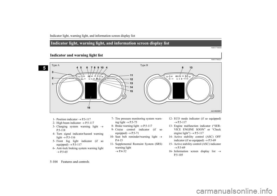
Indicator light, warning light, an
d information screen display list
5-104 Features and controls
5
N00557700048 N00557800267
Indicator light, warning light, and information screen display list Indicator and warning light list Type A Type B1- Position indicator
P.5-117
2- High beam indicator
P.5-117
3- Charging system warning light
P. 5 - 1 1 8
4- Turn signal indicator/hazard warning
light
P.5-116
5- Front fog light indicator (if so
equipped)
P.5-117
6- Anti-lock braking system warning light
P.5-65
7- Tire pressure monitoring system warn-
ing light
P.5-75
8- Brake warning light
P. 5 - 1 1 7
9- Cruise control indicator (if so
equipped)
P.5-71
10- Seat belt reminder/warning light
P. 4 - 1 5
11- Supplemental Restraint System (SRS)
warning light P.4-32
12- ECO mode indicator (if so equipped)
P.5-117
13- Engine malfunction indicator (“SER-
VICE ENGINE SOON” or “Check engine light”)
P.5-117
14- Active stability control (ASC) OFF
indicator (if so equipped)
P.5-69
15- Active stability control (ASC) indicator
P.5-69
16- Information screen display list
P.5-105
BK0202700US.book
104 ページ 2013年3月28日 木曜日 午前11時54分