maintenance MITSUBISHI OUTLANDER SPORT 2016 3.G Owners Manual
[x] Cancel search | Manufacturer: MITSUBISHI, Model Year: 2016, Model line: OUTLANDER SPORT, Model: MITSUBISHI OUTLANDER SPORT 2016 3.GPages: 398, PDF Size: 14.63 MB
Page 1 of 398
Table of contents
123456789101112
Overview Quick indexGeneral information Seat and restraint systems Features and controlsDriving safetyComfort controlsFor emergenciesVehicle care and maintenance Customer assistance/
Reporting Safety Defects
Specifications Alphabetical index
BK0229600US.bo
ok 1 ページ 2015年10月1日 木曜日 午後2時29分
Page 19 of 398
Modifications to and racing of your vehicle
General information 3-5
3
7. To close, turn the fuel tank filler pipe cap slowly clockwise until you hear clicking sounds, then gently push the fuel tank filler door closed.
N00301600149
This vehicle should not be modified withnon-Mitsubishi Motors genuine parts.Mitsubishi Motors designs and manufactures high quality vehicles
with an emphasis on
safety and durability. Modifications usingnon-Mitsubishi Motors genuine parts may affect the performance, safety and/or durabil- ity of your vehicle, and may violate applica-ble state and/or federal regulations. DAMAGE OR PERFORMANCE PROB- LEMS RESULTING FROM MODIFICA- TIONS TO OR RACING OF YOUR VEHICLE ARE NOT COVEREDUNDER WARRANTY. Examples of modifications to your vehicle that can cause damage or performance prob- lems include the following: Failure to use Mitsubishi Motors genuine parts Failure to use required fuel and fluids Failure to use proper size tires and wheels Modification of the fuel, intake, exhaust, emission, suspension, engine, drive train or electrical wiring systems
Modification of any onboard com- puter/control module, including repro- gramming, or replacing/adding chips to any onboard computer/control module
Review the Warranty and Maintenance Man- ual for further details regarding warranty cov- erage.
N00301700166
The installation of accessories, optional parts, etc., should only be carried outwithin the limits prescribed by law, and in accordance with the guidelines and warn- ings contained within the documentsaccompanying this vehicle. Only Mitsubishi Motors approved acces- sories should be fitted to your vehicle. Improper installation of electrical parts could cause fire. Refer to the “Modifica- tion/alterations to the electrical or fuelsystems” section within this owner’s manual.
WA R N I N G Make sure the fuel tank filler cap is securely closed. If the fuel cap were loose, fuel could leak, resulting in a fire.CAUTION If you need to replace the fuel tank filler cap, use only the cap specified for your model vehicle.NOTE
If the fuel tank filler cap
is not tight while
driving, the engine malfunction indicator (“SERVICE ENGINE SOON” or “Checkengine light”) may come on when the onboard diagnostic (OBD) system performs a self check. Always tighten the fuel tank filler cap until you hear at least 3 clicks.The indicator will go off after driving several times. If the indicator does not go off, con- tact your authorized Mitsubishi Motorsdealer or a repair f
acility of your choice as
soon as possible.
Modifications to and racing of your vehicle
Installation of accessories
CAUTION Before any electrical or electronic accesso- ries are installed, consult an authorized Mitsubishi Motors dealer.
BK0229600US.bo
ok 5 ページ 2015年10月1日 木曜日 午後2時29分
Page 20 of 398
Genuine Mitsubishi Motors parts 3-6 General information
3
Using a cellular phone or radio set inside the vehicle without an external antenna may cause electrical system interference, which could lead to unsafe vehicle opera-tion. Tires and wheels which do not meet spec- ifications must not be used.Refer to the “Specifications” section for information regarding wheel and tire sizes.
Due to the large number of accessory and replacement parts provided by different man-ufacturers in the market, it is not always pos- sible for an authorized Mitsubishi Motors dealer to check whether the attachment orinstallation of non-Mitsubishi Motors genu-
ine parts affects the driving safety of your Mitsubishi-vehicle.
N00301800138
Mitsubishi Motors ma
nufactures high quality
vehicles with an emphasis on safety. It is important to consult an authorized MitsubishiMotors dealer before installation of anyaccessory which may involve modification of the electrical or fuel systems.
N00301400219
Mitsubishi Motors Genuine Parts are designed and manufactured to meet high stan- dards of performance, and are recommended for all of your maintenance needs. Also avail-
able from your Mitsubishi Motors dealer are a wide variety of accessories to personalize your new vehicle. Each Mitsubishi Motors vehicle has a selection of Mitsubishi Motorsauthorized accessories to choose from to tai- lor your new vehicle to your own personal preference. Your Mitsubishi Motors dealer’sParts Manager has information on various audio systems, protection items, as well as interior and exterior accessories available foryour specific model.
N00300100017
Certain components of this vehicle, such asairbag modules, seat belt pretensioners, andbutton cell batteries, may contain perchlorate materials. Special handling may apply. For additionalinformation, see www.dtsc.ca.gov/hazardous- waste/perchlorate.
WA R N I N G While driving, do not use a cellular phone in a way that hinders safe driving. Any-thing, including cellular phone usage, that distracts you from the safe operation of your vehicle increases your risk of an acci-dent. Refer to and follow all state and local laws in your area regarding cellular phoneusage while driving.
Important point!
Modification/alterations to the electrical or fuel systems
CAUTION Please consult an authorized Mitsubishi Motors dealer concerning any such acces-sory fitment or modification. If the wires interfere with the vehicle body or improper installation methods are used (pro-tective fuses not included, etc.), electronic devices may be adversely affected, resulting in a fire, vehicle damage, or other accident.
Genuine Mitsubishi Motors parts
California Perchlorate Materials Requirements
BK0229600US.bo
ok 6 ページ 2015年10月1日 木曜日 午後2時29分
Page 21 of 398
4
Seat and restraint systemsSeats ..........................................
.......................................................4-2
Seats and restraint syst
ems ..............................................................4-2
Front seats .......................
.................................................................4-3
Rear seats ........................
.................................................................4-7
Head restraints ......
.................................................
..........................4-7
Extending a luggage comp
artment ..................................................4-9
Seat belts .........................
............................................................... 4-11
Seat belt use during preg
nancy ......................................................4-17
Seat belt pre-tensioner and fo
rce limiter systems ..........................4-17
Child restraint system
s ...........................................
........................4-18
Maintenance and inspection of seat belts ......................................4-25 Supplemental Restraint System (SRS) - airbag .............................4-26
BK0229600US.bo
ok 1 ページ 2015年10月1日 木曜日 午後2時29分
Page 45 of 398

Maintenance and inspection of seat belts
Seat and restraint systems 4-25
4
8. Before putting your child in the restraint, push and pull the restraint in all directions to be sure it is firmly secure. Do this before each use. If the child restraint sys-tem is not firmly secure, repeat steps 1 through 7. 9. To remove a child restraint system fromthe vehicle and deactivate the ALR mode, remove the child from the restraint. Unlatch the buckle. Then remove the beltfrom the restraint and let the belt fully retract.
10. Reinstall the head restraint.
Refer to “Head restraints” on page 4-7.
N00407601673
Children who have outgrown a child restraint system should be seated in the rear seat and wear the seat belt. If the shoulder belt crossestheir face or neck, and/or the lap belt crosses
their stomach, a commercially available booster seat must be used to raise the child so that the shoulder belt crosses their shoulder and the lap belt remains positioned lowacross their hips. The booster seat should fit the vehicle seat and have a label certifying compliance with Federal Motor VehicleSafety Standards or Motor Vehicle Restraint Systems and Booster Seats Safety Regula- tions.
N00407000221
The seat belt webbing may be cleaned withmild soap or detergent solution. Do not use anorganic solvent. Allow the belts to dry in the shade. Do not allow them to retract until com- pletely dry. Do not attempt to bleach or re-dye the belts. The color may rub off and the webbing strength may be affected. Regularly check your seat belt buckles and their release mechanisms for positive engage- ment and release of the latch plate. Check theretractors for automatic locking when in the Automatic Locking Retractor function. The entire seat belt assembly should be replaced if the webbing shows any obviouscuts, tears, increase in thickness in any sec- tion of the webbing from broken fibers, or severe fading from sunlight. All of these con-ditions indicate a weakening of the belt, which may adversely affect seat belt perfor- mance in an accident.
WA R N I N G Child restraint system tether anchors are designed only to withstand loads from cor- rectly fitted child restraint systems. Under no circumstances are they to be used for adult seat belts, or harnesses, or forattaching other items or equipment to the vehicle.
Children who have outgrown child restraint systems
WA R N I N G Any child who is too small to properly wear a seat belt must be properlyrestrained in an appropriate child restraint system, to reduce their risk of serious injury or death in an accident. A child should never be left unattended in, or unsupervised around, your vehicle.When you leave the vehicle, always take the child out as well. Children can die from heat stroke if left or trapped inside the vehicle, especially on hot days. Keep your vehicle locked when not in use. Keep your vehicle keys away from chil- dren.
Maintenance and inspection of seat belts
BK0229600US.bo
ok 25 ページ 2015年10月1日 木曜日 午後2時29分
Page 61 of 398
Supplemental Restraint System (SRS) - airbag
Seat and restraint systems 4-41
4
N00408500698
SRS servicing
WA R N I N G Any maintenance performed on or near the components of the SRS should be per- formed only by an authorized Mitsubishi Motors dealer. Do not permit anyone elseto do any service, inspection, maintenance or repair on any SRS components or wir- ing. Similarly, no part of the SRS shouldever be handled, removed or disposed by anyone except an authorized Mitsubishi Motors dealer.Improper work methods on the SRS com- ponents or wiring could result in an acci- dental airbag deployment or could makethe SRS inoperable. Either of these situa- tions could result in serious injury or death. Do not modify your steering wheel or any other SRS component or related vehiclepart. For example, replacement of the steering wheel, or modifications to the front bumper or body structure canadversely affect SRS performance and may lead to injury. If your vehicle has received any damage, you should have the SRS inspected by an authorized Mitsubishi Motors dealer to make sure it is in proper working order.
Do not modify your front seats, center pil- lar or center console. Such modifications can adversely affect SRS performance and may lead to injury. Also, if you discover any tear or openseam in the seat fabric near the side air- bag, have the seat inspected by an autho- rized Mitsubishi Motors dealer. If you have found any scratch, crack or damage to the portion of the front andrear pillars and roof side rail, you should have the SRS inspected by an authorized Mitsubishi Motors dealer.NOTE
When you transfer ownership of the vehicle to another person, we urge you to alert the new owner that it is equipped with the SRS and refer that owner to the applicable sec-tions in this owner’s manual. If you decide to junk or scrap your vehicle, we urge you to first take
it to an authorized
Mitsubishi Motors dealer so that the SRS can be made safe for disposal. If any of the following parts needs to be modified for use by a handicapped person, the advanced airbag system will be greatly affected. Please consult an authorizedMitsubishi Motors dealer. • Driver’s seat• Front passenger seat • Front seat beltWA R N I N G
• Steering wheel • Instrument panel[For vehicles sold in U.S.A.] To contact Mitsubishi Motors North America, Inc. call 1-888-648-7820 or write to:Mitsubishi Motors North America, Inc. Customer Relations Department P.O. Box 6400Cypress, CA 90630-0064 [For vehicles sold in Canada] To contact Mitsubishi Motor Sales of Canada, Inc. call 1-888-576-4878 or write to:Mitsubishi Motor Sales of Canada, Inc. Customer Relations Department P.O. Box 410094141 Dixie Road Mississauga, ON L4W 5C9 [For vehicles sold in Puerto Rico] To contact Mitsubishi Motor Sales ofCaribbean, Inc. call 1-787-251-8715 or write to: Mitsubishi Motor Sales of Caribbean,Inc. Customer Service Department P.O. Box 192216SAN JUAN PR 00919-2216NOTE
BK0229600US.bo
ok 41 ページ 2015年10月1日 木曜日 午後2時29分
Page 63 of 398
5
Features and controlsBreak-in recommendation
s ..............................................................5-3
Keys ..........................................
.......................................................5-3
Electronic immobilizer (Anti-thef
t starting system) ........................5-4
Keyless entry system (if so equipped) ..............................................5-7Free-hand Advanced Security Transmitter (F.A.S.T.-key) (if so equipped)
.................................................
........................5-12
Door locks .......................
...............................................................5-28
Power door locks ............
...............................................................5-30
Child safety locks for r
ear door .....................................................5-31
Liftgate ......................................
.....................................................5-32
Inside liftgate releas
e .............................................
........................5-33
Theft-alarm system
................................................
........................5-34
Power window control
...........................................
........................5-37
Sunshade (if so equi
pped)..............................................................5-39
Parking brake ..................
...............................................................5-40
Steering wheel height and reach adjustment ..................................5-41Inside rearview mirro
r ...........................................
........................5-42
Outside rearview mirr
ors ...............................................................5-44
Ignition switch ......
.................................................
........................5-46
Starting the engine
.................................................
........................5-47
Manual transaxle (if so equipped) .................................................5-49 Continuously variable transmission
(CVT) (if so equipped).........5-51
Electronically controlled 4WD system (if so equipped)................5-584-wheel drive operation
.........................................
........................5-60
Inspection and maintenance following rough road operation ........5-63 Cautions on the handling of 4-wheel drive vehicles ......................5-63Service brake ..................
...............................................................5-64
Hill start assist .......
.................................................
........................5-65
Brake assist system
...............................................
......................... 5-66
Anti-lock braking syst
em .....................................
......................... 5-67
Electric power steering syst
em (EPS) ........................................... 5-69
Active stability control
(ASC) ....................
................................... 5-70
Cruise control (if so eq
uipped) ...................................................... 5-73
Tire pressure monitoring
system ................................................... 5-77
Rear-view camera (if so eq
uipped) ................................................ 5-81
Instrument cluster
.................................................
......................... 5-83
Multi-information disp
lay ....................................
......................... 5-85
Indicator light, warning light, and information screen disp
lay list ................................................. 5-106
Indicators .................................
.................................................... 5-119
Warning lights ................
.................................................
............. 5-120
Information screen disp
lay ...................................
....................... 5-121
Combination headlights and dimmer switch ............................... 5-123 Headlight leveling switch (if so equipped).................................. 5-129Turn signal lever ..
.................................................
....................... 5-129
Hazard warning flasher
switch .................................................... 5-130
Front fog light switch (if
so equipped) ........................................ 5-130
Wiper and washer swit
ch ......................................
....................... 5-130
Electric rear window def
ogger switch ......................................... 5-136
Horn switch .............................
.................................................... 5-136
Link System (if so equi
pped) .....................
................................. 5-137
Bluetooth
® 2.0 interface (if so
equipped)..................................... 5-137
USB input terminal (if so
equipped) ........................................... 5-160
Sun visors ......................
.................................................
............. 5-163
12 V power outlets .........
.................................................
............. 5-164
HomeLink
® Wireless Control System (if so equipped) ............... 5-165
BK0229600US.bo
ok 1 ページ 2015年10月1日 木曜日 午後2時29分
Page 123 of 398
4-wheel drive operation
Features and controls 5-61
5
When turning a sharp corner in “4WD LOCK” position at low speed, a slight differ- ence in steering may be experienced similarto feeling as if the brakes were applied. This
is called tight corner braking and results from each of the four tires being at a different dis- tance from the corner. The phenomenon is typical of 4-wheel drive vehicles. If thisoccurs, either straighten out the steering wheel or change to another mode. Set the drive mode-selector to “4WD AUTO” conditions, and then gradually depress the accelerator pedal for a smooth start.
WA R N I N G Do not over-rely on the 4-wheel drive vehi- cles. Even 4-wheel drive vehicles have lim- its to the system and ability to maintain control and traction. Reckless driving may lead to accidents. Always drive carefully,taking account of the road conditions. Improperly operating this vehicle on or off-pavement can cause an accident or rollover in which you and your passengers could be seriously injured or killed.• Follow all instructio
ns and guidelines in
the owner’s manual.• Keep your speed low and do not drivefaster than conditions.NOTE
Driving on rough roads can be hard on a vehicle. Before you leave the pavement, be sure all scheduled maintenance and servicehas been done, and that you have inspected your vehicle. Pay special attention to the condition of the tires, and check the tire pres-sures. Mitsubishi Motors is not responsible to the operator for any damage or injury caused or liability incurred by improper and negligentoperation of a vehicle. All techniques of vehicle operation depend on the skill and experience of the operator and other partici-pating parties. Any deviation from the rec- ommended operating instructions above is at their own risk.
Note that the stopping distance required of the 4-wheel drive vehicle differs very little from that of the front-wheel drive vehicle. When driving on a snow-covered road or a slippery, muddy surface, make sure that youkeep a sufficient distance between your vehi- cle and the one ahead of you. The driving posture should be more upright; adjust the seat to a good position for easy steering and pedal operation. Be sure to wearthe seat belt. After driving on rough roads, check each part of the vehicle and wash it thoroughly with water. Refer to the “Inspection and maintenance following rough road opera-tion” section and “Vehicle care and Mainte- nance” sections.CAUTION Setting the drive mode-selector to “4WD LOCK” position to drive on dry paved roadwill increase fuel consumption, with possible noise generation.
Turning sharp corners
NOTE
On snowy or icy roads
NOTE
The use of snow tires is recommended. Maintain a safe distance between vehicles, avoid sudden braking, and use engine brak- ing (downshifting).CAUTION Avoid sudden braking, sudden acceleration and sharp turning. Skidding occurs and con- trol of the vehicle could be lost.
BK0229600US.bo
ok 61 ページ 2015年10月1日 木曜日 午後2時29分
Page 125 of 398
Inspection and maintenance fo
llowing rough road operation Features and controls 5-63
5
N00530700098
After operating the vehicle in rough road con- ditions, be sure to perform the following inspection and maintenance procedures: Check that the vehicle has not been dam- aged by rocks, gravel, etc. Carefully wash the vehicle with water. Drive the vehicle slowly while lightlydepressing the brake pedal in order to dry out the brakes. If the brakes still do not function properly, co
ntact an authorized
Mitsubishi Motors dealer or a repair facil- ity of your choice as soon as possible to have the brakes checked. Remove the insects, dried grass, etc. clog- ging the radiator core.
After driving through water, check the engine, transaxle and differential oil. If the oil or grease is milky or cloudy because of water contamination, it mustbe replaced with new oil. Check the inside of the vehicle. If water entry is found, dry the carpet etc. Inspect the headlights. If water is in the headlight housing, have it drained at an authorized Mitsubishi Motors dealer or arepair facility of your choice. Have an authorized Mitsubishi Motors dealer replace grease in the wheel bear- ings.
N00530800187
Since the driving torque can be applied to thefour wheels, the driving performance of thevehicle when operating in 4-wheel drive is greatly affected by the condition of the tires. Pay close attention to the tires. Install only the specified tires on all wheels. Refer to “Tires and wheels” onpage 11-5.
Be sure all four tires and wheels are the same size and type. When it is necessary to replace any of the tires or wheels, replace all four. All tires should be rotated before the wear difference between the front and rear tires is recognizable.
Good vehicle performance cannot be expected if there is a difference in wear between tires. Refer to “Tire rotation” on page 9-19. Check the tire inflation pressure regularly.
After driving through water, apply the brakes to be sure they are functioning properly. If the brakes are wet and not functioning prop- erly, dry them out by driving slowly while lightly depressing the brake pedal. Inspecteach part of the vehicle carefully.
Inspection and maintenance following rough road opera-tion
CAUTION
Cautions on the handling of 4-wheel drive vehicles Tires and wheels
CAUTION Always use tires of the same size, type, and brand that have no wear differences. Usingtires of different size, type, brands or degree of wear, will increase the differential oil tem- perature and result in possible damage to thedriving system. Further, the drive train will be subject to excessive loading, possibly leading to oil leakage, component seizure, orother serious failures.
BK0229600US.bo
ok 63 ページ 2015年10月1日 木曜日 午後2時29分
Page 141 of 398
Tire pressure monitoring system
Features and controls 5-79
5
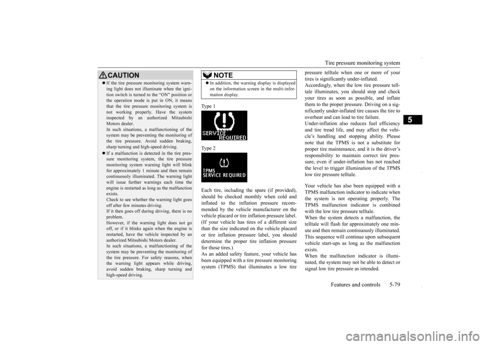
Type 1 Type 2Each tire, including the spare (if provided), should be checked monthly when cold and inflated to the inflation pressure recom-mended by the vehicle manufacturer on the vehicle placard or tire inflation pressure label. (If your vehicle has tires of a different sizethan the size indicated on the vehicle placard or tire inflation pressure label, you should determine the proper tire inflation pressurefor those tires.) As an added safety feature, your vehicle has been equipped with a ti
re pressure monitoring
system (TPMS) that illuminates a low tire
pressure telltale when one or more of your tires is significantly under-inflated. Accordingly, when the low tire pressure tell- tale illuminates, you should stop and checkyour tires as soon as possible, and inflate them to the proper pres
sure. Driving on a sig-
nificantly under-inflated tire causes the tire tooverheat and can lead to tire failure. Under-inflation also reduces fuel efficiency and tire tread life, and may affect the vehi-cle’s handling and stopping ability. Pleasenote that the TPMS is not a substitute for proper tire maintenance, and it is the driver’s responsibility to maintain correct tire pres-sure, even if under-inflation has not reached the level to trigger illumination of the TPMS low tire pressure telltale. Your vehicle has also been equipped with a TPMS malfunction indicator to indicate when the system is not operating properly. The TPMS malfunction indicator is combinedwith the low tire pressure telltale. When the system detects a malfunction, the telltale will flash for approximately one min-ute and then remain continuously illuminated. This sequence will continue upon subsequent vehicle start-ups as long as the malfunctionexists. When the malfunction indicator is illumi- nated, the system may not be able to detect orsignal low tire pressure as intended.
CAUTION If the tire pressure monitoring system warn- ing light does not illuminate when the igni- tion switch is turned to the “ON” position or the operation mode is put in ON, it means that the tire pressure monitoring system isnot working properly. Have the system inspected by an authorized Mitsubishi Motors dealer.In such situations,
a malfunctioning of the
system may be preventing the monitoring of the tire pressure. Avoid sudden braking,sharp turning and high-speed driving. If a malfunction is detected in the tire pres- sure monitoring system, the tire pressure monitoring system warning light will blink for approximately 1 minute and then remaincontinuously illuminated. The warning light will issue further warnings each time the engine is restarted as long as the malfunctionexists. Check to see whether the warning light goes off after few minutes driving.If it then goes off during driving, there is no problem. However, if the warning light does not gooff, or if it blinks again when the engine is restarted, have the vehicle inspected by an authorized Mitsubishi Motors dealer. In such situations,
a malfunctioning of the
system may be preventing the monitoring ofthe tire pressure. For safety reasons, when the warning light appears while driving, avoid sudden braking, sharp turning andhigh-speed driving.
NOTE
In addition, the warning display is displayed on the information screen in the multi-infor- mation display.
BK0229600US.bo
ok 79 ページ 2015年10月1日 木曜日 午後2時29分