MITSUBISHI PAJERO IV 2011 Owners Manual
Manufacturer: MITSUBISHI, Model Year: 2011, Model line: PAJERO IV, Model: MITSUBISHI PAJERO IV 2011Pages: 377, PDF Size: 29.43 MB
Page 131 of 377
Parking brake
E00600501360
To park the
vehicle, first bring it to a complete
stop, fully apply the parking brake lever sufficient-
ly to hold the vehicle.
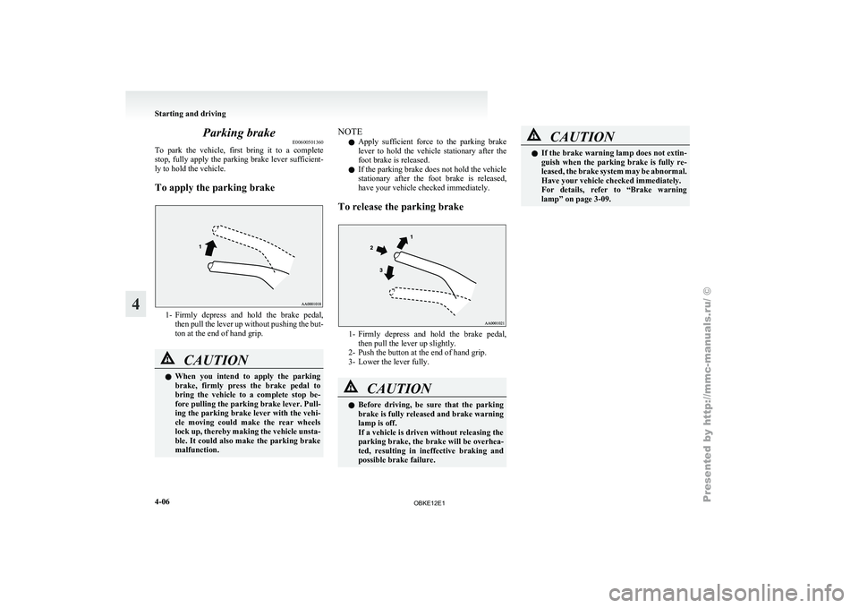
To apply the parking brake 1- Firmly depress and hold the brake pedal,
then pull
the lever up without pushing the but-
ton at the end of hand grip. CAUTION
l
When you
intend
to apply the parking
brake, firmly press the brake pedal to
bring the vehicle to a complete stop be-
fore pulling the parking brake lever. Pull-
ing the parking brake lever with the vehi-
cle moving could make the rear wheels
lock up, thereby making the vehicle unsta-
ble. It could also make the parking brake
malfunction. NOTE
l Apply
sufficient force
to the parking brake
lever to hold the vehicle stationary after the
foot brake is released.
l If the parking brake does not hold the vehicle
stationary after the foot brake is released,
have your vehicle checked immediately.
To release the parking brake 1- Firmly depress and hold the brake pedal,
then pull the lever up slightly.
2- Push the button at the end of hand grip.
3-
Lower the lever fully. CAUTION
l
Before driving,
be
sure that the parking
brake is fully released and brake warning
lamp is off.
If a vehicle is driven without releasing the
parking brake, the brake will be overhea-
ted, resulting in ineffective braking and
possible brake failure. CAUTION
l
If the brake
warning lamp does not extin-
guish when the parking brake is fully re-
leased, the brake system may be abnormal.
Have your vehicle checked immediately.
For details, refer to “Brake warning
lamp” on page 3-09. Starting and driving
4-06
4
OBKE12E1
Page 132 of 377

Parking
E00600601097
To park the
vehicle, fully engage the parking
brake, and then move the gearshift lever to 1 st
or
“R” (Reverse) position for vehicles with M/T, or
set the selector lever to “P” (PARK) position on
A/T vehicles.
Parking on a hill
To prevent the vehicle from rolling, follow these
procedures:
Parking on a downhill slope
Turn the front wheels towards the kerb and move
the vehicle forward until the kerb side wheel gently
touches the kerb.
Apply the parking brake and place the gearshift lev-
er into the “R” (Reverse) position (with M/T) or
the selector lever into the “P” (PARK) position
(with A/T).
If necessary, apply chocks to wheels.
Parking on an uphill slope
Turn the front wheels away from the kerb and
move the vehicle back until the kerb side wheel gen-
tly touches the kerb.
Apply the parking brake and place the gearshift lev-
er into the 1 st
position (with M/T) or the selector lev-
er into the “P” (PARK) position (with A/T).
If necessary, apply chocks to wheels. NOTE
l If
your vehicle
is equipped with A/T, be sure
to apply the parking brake before moving the
selector lever to the “P” (PARK) position. If
you move the selector lever to the “P”
(PARK) position before applying the parking
brake, it may be difficult to disengage the se-
lector lever from the “P” (PARK) position
when next you drive the vehicle, requiring ap-
plication of a strong force to the selector lev-
er to move from the “P” (PARK) position.
Parking with the engine running
Never leave the engine running while you take a
short sleep/rest, or you open or close a gate or ga-
rage door, etc. Also, never leave the engine run-
ning in a closed or poorly ventilated place. WARNING
l Leaving
the
engine
running risks injury
or death from accidentally moving the
gearshift lever (on M/T vehicles) or the se-
lector lever (on A/T vehicles) or the accu-
mulation of toxic exhaust fumes in the pas-
senger compartment.
Where you park WARNING
l Do not
park
your vehicle in areas where
combustible materials such as dry grass
or leaves can come in contact with a hot
exhaust, since a fire could occur. When leaving the vehicle
Always remove
the
key from the ignition switch
and lock all doors (including the backdoor) when
leaving the vehicle unattended.
Always try to park your vehicle in a well lit area. Starting and driving
4-07 4
OBKE12E1
Page 133 of 377
Steering wheel height adjustment
E00600700222
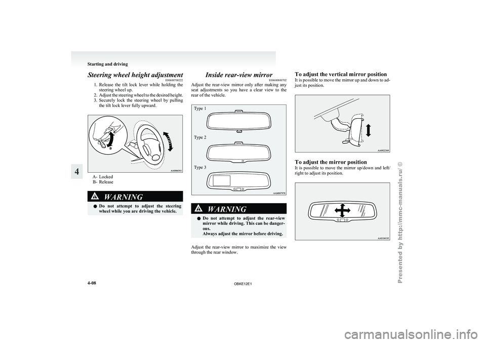
1. Release the tilt
lock lever while holding the
steering wheel up.
2. Adjust the steering wheel to the desired height.
3. Securely lock the steering wheel by pulling the tilt lock lever fully upward. A- Locked
B- Release WARNING
l Do not attempt
to adjust the steering
wheel while you are driving the vehicle. Inside rear-view mirror
E00600800702
Adjust the rear-view
mirror only after making any
seat adjustments so you have a clear view to the
rear of the vehicle.
Type 1
Type 2
Type 3 WARNING
l Do not attempt
to adjust the rear-view
mirror while driving. This can be danger-
ous.
Always adjust the mirror before driving.
Adjust the rear-view mirror to maximize the view
through the rear window. To adjust the vertical mirror position
It
is possible
to move the mirror up and down to ad-
just its position. To adjust the mirror position
It is
possible
to move the mirror up/down and left/
right to adjust its position. Starting and driving
4-08
4
OBKE12E1
Page 134 of 377

To reduce the glare
Type 1
The lever
(A)
at the bottom of the mirror can be
used to adjust the mirror to reduce the glare from
the headlamps of vehicles behind you during night
driving. 1- Normal
2- Anti-glare
Type 2
When the headlamps of the vehicles behind you are
very bright, the
reflection factor of the rear-view
mirror is automatically changed to reduce the glare. When the ignition switch is turned to the “ON” po-
sition, the reflection factor of the mirror is automat-
ically changed.
NOTE
l Do
not hang
items on, or spray glass cleaner
on the sensor (1), as reduced sensitivity
could result. Type 3
When the headlamps of the vehicles behind you are
very bright, the
reflection factor of the rear-view
mirror is automatically changed to reduce the glare. When the ignition switch is turned to the “ON” po-
sition, the
green
indicator (1) illuminates and the re-
flection factor of the mirror is automatically
changed.
NOTE
l Do not hang any items on, or spray glass clean-
er on the sensors (2) on the front and back
side, as reduced sensitivity could result.
l If you want to stop automatic mode, press
the switch (3) and the indicator will go off.
To return to automatic mode, press the
switch again or turn the ignition key to the
“ON” position after turning to “LOCK” or
“ACC” position. Starting and driving
4-09 4
OBKE12E1
Page 135 of 377
Outside rear-view mirrors
E00600900484
Compound curved-surface mirror*
On the driver’s
side, a compound curved-surface
mirror is used, while on the front passenger’s side,
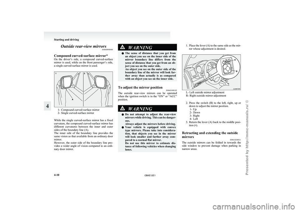
a single curved-surface mirror is used. 1- Compound curved-surface mirror
2- Single curved-surface mirror
While the
single curved-surface mirror has a fixed
curvature, the compound curved-surface mirror has
different curvatures between the inner and outer
sides of the boundary line (A).
The inner side of the boundary line provides the
same vision as that available from an ordinary door
mirror.
However, the outer side of the boundary line pro-
vides a wider angle of vision compared to an ordi-
nary door mirror. WARNING
l The sense of
distance that you get from
an object you see on the inner side of the
mirror boundary line differs from the
sense of distance that you get from an ob-
ject you see on the outer side.
An object you see on the outer side of the
boundary line of the mirror will look far-
ther away than actually is as compared
with an object you see on the inner side.
To adjust the mirror position E00601000105
The outside rear-view mirrors can be operated
when the ignition
switch is in the “ON” or “ACC”
position. WARNING
l Do not attempt
to adjust the rear-view
mirrors while driving. This can be danger-
ous.
Always adjust the mirrors before driving.
l Your vehicle is equipped with convex
type mirrors. Please take into considera-
tion, that objects you see in the mirror
will look smaller and farther away com-
pared to a normal flat mirror.
Do not use this mirror to estimate dis-
tance of following vehicles when changing
lanes. 1. Place the lever (A) to the same side as the mir-
ror whose adjustment is desired. L- Left outside mirror adjustment
R- Right outside mirror adjustment
2. Press the switch
(B) to the left, right, up or
down to adjust the mirror position. 1- Up
2- Down
3- Right
4- Left
3. Return the lever (A) back to the middle posi- tion (•).
Retracting and extending the outside
mirrors E00618200011
The outside mirrors can be folded in towards the
side window to
prevent damage when parking in
narrow areas. Starting and driving
4-10
4
OBKE12E1
Page 136 of 377
CAUTION
l
Do not drive the vehicle with the mirror
folded in. The lack of rearward visibility
normally provided the mirror could lead
to an accident.
Retracting and extending the mirrors using the
mirror retractor switch
With the ignition
switch in the “ON” or “ACC” po-
sition, push the mirror retractor switch to retract
the mirrors. Push it again to extend the mirrors to
their original positions.
After placing the ignition switch in the “LOCK” po-
sition, it is possible to retract and extend the mir-
rors using the mirror retractor switch for about
30 seconds. CAUTION
l
It is possible
to retract and extend the mir-
rors by hand. After retracting a mirror us-
ing the mirror retractor switch, however,
you should extend it by using the switch
again, not by hand. If you extended the
mirror by hand after retracting it using
the switch, it would not properly lock in
position. As a result, it could move be-
cause of the wind or vibration while you
are driving, taking away your rearward
visibility.
NOTE l Be
careful not
to get your hands trapped
while a mirror is moving.
l If you move a mirror by hand or it moves af-
ter hitting a person or object, you may not be
able to return it to its original position using
the mirror retractor switch. If this happens,
push the mirror retractor switch to place the
mirror in its retracted position and then push
the switch again to return the mirror to its orig-
inal position.
l If the battery voltage is low and you start the
engine while extending the mirrors, the mir-
rors may stop part-way. If this happens, push
the mirror retractor switch to retract the mir-
rors and then push the switch again to extend
them.
l When freezing has occurred and mirrors fail
to operate as intended, please refrain from re-
peated pushing of the retractor switch as this
action can result in burn-out of the mirror mo-
tor circuits. Automatic extension of mirrors
If
the
engine
is stopped and started with the mirrors
retracted, the mirrors automatically extend for safe-
ty when the vehicle speed reaches 30 km/h
(19 mph).
Heated mirror* E00601200312
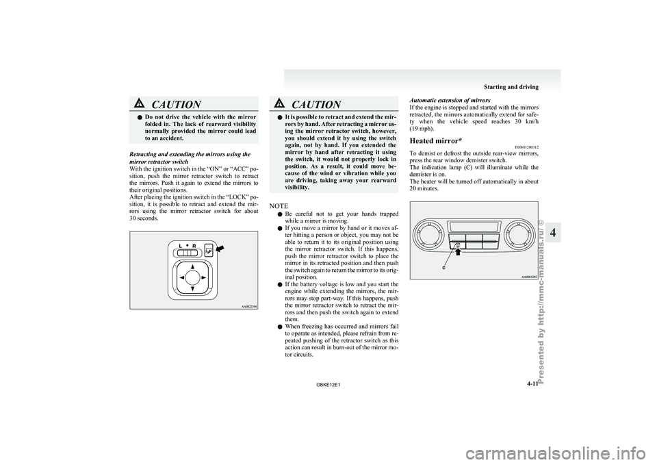
To demist or defrost the outside rear-view mirrors,
press the rear window demister switch.
The indication lamp
(C) will illuminate while the
demister is on.
The heater will be turned off automatically in about
20 minutes. Starting and driving
4-11 4
OBKE12E1
Page 137 of 377
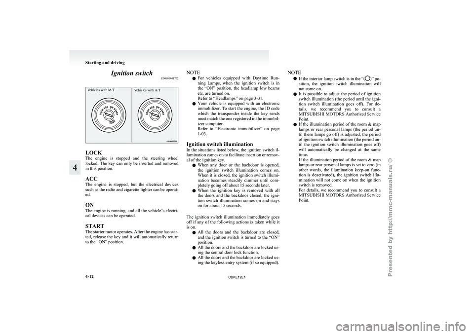
Ignition switch
E00601401702Vehicles with M/T Vehicles with A/TLOCK
The
engine is
stopped and the steering wheel
locked. The key can only be inserted and removed
in this position.
ACC
The engine is stopped, but the electrical devices
such as the radio and cigarette lighter can be operat-
ed.
ON
The engine is running, and all the vehicle’s electri-
cal devices can be operated.
START
The starter motor operates. After the engine has star-
ted, release the key and it will automatically return
to the “ON” position. NOTE
l For
vehicles equipped
with Daytime Run-
ning Lamps, when the ignition switch is in
the “ON” position, the headlamp low beams
etc. are turned on.
Refer to “Headlamps” on page 3-31.
l Your vehicle is equipped with an electronic
immobilizer. To start the engine, the ID code
which the transponder inside the key sends
must match the one registered in the immobil-
izer computer.
Refer to “Electronic immobilizer” on page
1-03.
Ignition switch illumination
In the situations listed below, the ignition switch il-
lumination comes on to facilitate insertion or remov-
al of the ignition key. l When any door or the backdoor is opened,
the ignition switch illumination comes on.
When it is closed, the ignition switch illumi-
nation becomes steadily dimmer until com-
pletely going off about 15 seconds later.
l When the ignition key is removed with all
the doors and the backdoor closed, the igni-
tion switch illumination comes on and stays
on for about 15 seconds.
The ignition switch illumination immediately goes
off if any of the following actions is taken while it
is on. l All the doors and the backdoor are closed,
and the ignition switch is turned to the “ON”
position.
l All the doors and the backdoor are locked us-
ing the central door lock function.
l All the doors and the backdoor are locked us-
ing the keyless entry system (if so equipped). NOTE
l If the interior
lamp switch is in the “( )” po-
sition, the ignition
switch illumination will
not come on.
l It is possible to adjust the period of ignition
switch illumination (the period until the igni-
tion switch illumination goes off). For de-
tails, we recommend you to consult a
MITSUBISHI MOTORS Authorized Service
Point.
l If the illumination period of the room & map
lamps or rear personal lamps (the period un-
til these lamps go off) is adjusted, the period
of ignition switch illumination (the period un-
til the ignition switch illumination goes off)
will automatically be changed at the same
time.
If the illumination period of the room & map
lamps or rear personal lamps is set to zero (in
other words, the illumination keep-on func-
tion is deactivated), the ignition switch illu-
mination will not come on when the ignition
switch is removed.
For details, we recommend you to consult a
MITSUBISHI MOTORS Authorized Service
Point. Starting and driving
4-12
4
OBKE12E1
Page 138 of 377
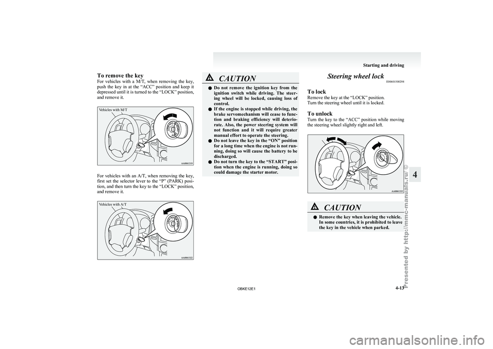
To remove the key
For vehicles
with
a M/T, when removing the key,
push the key in at the “ACC” position and keep it
depressed until it is turned to the “LOCK” position,
and remove it.
Vehicles with M/T For vehicles with an A/T, when
removing
the key,
first set the selector lever to the “P” (PARK) posi-
tion, and then turn the key to the “LOCK” position,
and remove it.
Vehicles with A/T CAUTION
l
Do not remove
the ignition key from the
ignition switch while driving. The steer-
ing wheel will be locked, causing loss of
control.
l If the engine is stopped while driving, the
brake servomechanism will cease to func-
tion and braking efficiency will deterio-
rate. Also, the power steering system will
not function and it will require greater
manual effort to operate the steering.
l Do not leave the key in the “ON” position
for a long time when the engine is not run-
ning, doing so will cause the battery to be
discharged.
l Do not turn the key to the “START” posi-
tion when the engine is running, doing so
could damage the starter motor. Steering wheel lock
E00601500298
To lock
Remove the key at the “LOCK” position.
Turn the steering wheel until it is locked.
To unlock
Turn the key
to the “ACC” position while moving
the steering wheel slightly right and left. CAUTION
l
Remove the key when leaving the vehicle.
In some countries, it is prohibited to leave
the key in the vehicle when parked. Starting and driving
4-13 4
OBKE12E1
Page 139 of 377
Starting
E00601600811
Tips for starting l Do not
operate
the starter motor continuous-
ly longer than 10 seconds; doing so could
run down the battery. If the engine does not
start, turn the ignition key back to “LOCK”
position, wait a few seconds, and then try
again. Trying repeatedly with the starter mo-
tor still turning will damage the starter mech-
anism. WARNING
l Never
run
the
engine in a closed or poor-
ly ventilated area any longer than is nee-
ded to move your vehicle in or out of the
area. Carbon monoxide gases are odour-
less and can be fatal. CAUTION
l
Never attempt to
start the engine by push-
ing or pulling the vehicle.
l Do not run the engine at high rpm or
drive the vehicle at high speed until the en-
gine has had a chance to warm up.
l Release the ignition key as soon as the en-
gine starts to avoid damaging the starter
motor.
l If your vehicle is equipped with a turbo-
charger, do not stop the engine immedi-
ately after high-speed or uphill driving.
First allow the engine to idle to give the
turbocharger a chance to cool down. Starting the engine (petrol-powered ve-
hicles)
E00601701994
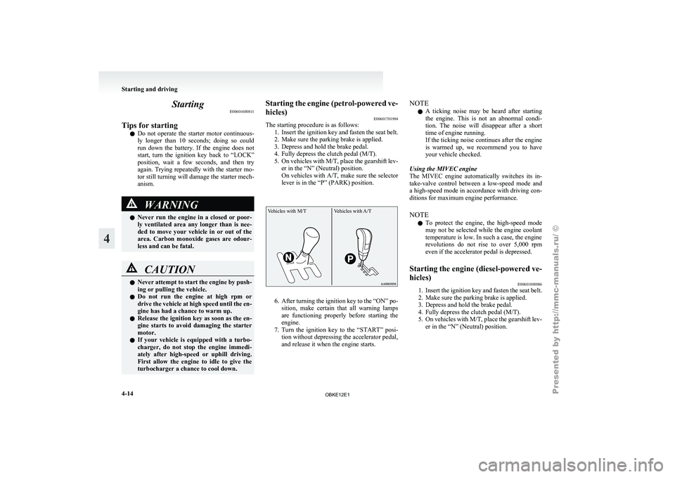
The starting procedure is as follows:
1. Insert the ignition
key and fasten the seat belt.
2. Make sure the parking brake is applied.
3. Depress and hold the brake pedal.
4. Fully depress the clutch pedal (M/T).
5. On vehicles with M/T, place the gearshift lev- er in the “N” (Neutral) position.
On vehicles with A/T, make sure the selector
lever is in the “P” (PARK) position.
Vehicles with M/T Vehicles with A/T 6. After turning the ignition key to the “ON” po-
sition, make
certain that all warning lamps
are functioning properly before starting the
engine.
7. Turn the ignition key to the “START” posi- tion without depressing the accelerator pedal,
and release it when the engine starts. NOTE
l A
ticking noise
may be heard after starting
the engine. This is not an abnormal condi-
tion. The noise will disappear after a short
time of engine running.
If the ticking noise continues after the engine
is warmed up, we recommend you to have
your vehicle checked.
Using the MIVEC engine
The MIVEC engine automatically switches its in-
take-valve control between a low-speed mode and
a high-speed mode in accordance with driving con-
ditions for maximum engine performance.
NOTE l To protect the engine, the high-speed mode
may not be selected while the engine coolant
temperature is low. In such a case, the engine
revolutions do not rise to over 5,000 rpm
even if the accelerator pedal is depressed.
Starting the engine (diesel-powered ve-
hicles) E00601800086
1. Insert the ignition key and fasten the seat belt.
2. Make sure the parking brake is applied.
3.
Depress and hold the brake pedal.
4. Fully depress the clutch pedal (M/T).
5. On vehicles with M/T, place the gearshift lev- er in the “N” (Neutral) position. Starting and driving
4-14
4
OBKE12E1
Page 140 of 377
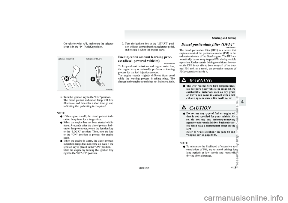
On vehicles with A/T, make sure
the selector
lever is in the “P” (PARK) position.
Vehicles with M/T Vehicles with A/T6. Turn the ignition key to the “ON” position.
The diesel preheat
indication lamp will first
illuminate, and then after a short time go out,
indicating that preheating is completed.
NOTE l If the engine is cold, the diesel preheat indi-
cation lamp is on for a longer time.
l When the engine has not been started within
about 5 seconds after the diesel preheat indi-
cation lamp went out, return the ignition key
to the “LOCK” position. Then, turn the key
to the “ON” position to preheat the engine
again.
l When the engine is warm, the diesel preheat
indication lamp does not come on even if the
ignition key is placed in the “ON” position.
Start the engine by turning the ignition key
right to the “START” position. 7. Turn the ignition key to the “START” posi-
tion without depressing the accelerator pedal,
and release it when the engine starts.
Fuel injection amount learning proc-
ess (diesel-powered vehicles) E00616000044
To keep
exhaust emissions and engine noise low,
the engine very
occasionally performs a learning
process for the fuel injection amount.
The engine sounds slightly different from usual
while the learning process is taking place. The
change in the engine sound does not indicate a fault. Diesel particulate filter (DPF)*
E00619800027
The diesel particulate
filter (DPF) is a device that
captures most of the particulate matter (PM) in the
exhaust emissions of the diesel engine. The DPF au-
tomatically burns away trapped PM during vehicle
operation. Under certain driving conditions, howev-
er, the DPF is not able to burn away all of the trap-
ped PM and, as a result, an excessive amount of
PM accumulates inside it. WARNING
l The DPF reaches very high temperatures.
Do not
park
your vehicle in areas where
combustible materials such as dry grass
or leaves can come in contact with a hot
exhaust system since a fire could occur. CAUTION
l
Do not use
any type of fuel or engine oil
that is not specified for your vehicle. Al-
so, do not use any moisture-removing
agent or other fuel additive. Such substan-
ces could have a detrimental effect on the
DPF.
Refer to “Fuel selection” on page 02 and
“Engine oil” on page 8-04.
NOTE l To
minimize the
likelihood of excessive ac-
cumulation of PM, try to avoid driving for
long periods at low speeds and repeatedly
driving short distances. Starting and driving
4-15 4
OBKE12E1