MITSUBISHI PAJERO IV 2011 Owners Manual
Manufacturer: MITSUBISHI, Model Year: 2011, Model line: PAJERO IV, Model: MITSUBISHI PAJERO IV 2011Pages: 377, PDF Size: 29.43 MB
Page 181 of 377
Cargo loads
E00609901224
Cargo loads precautions CAUTION
l
When
loading
luggage, be careful to the
following. • Stow cargo and luggage in the luggagecompartment whenever possible.
• Distribute cargo or luggage evenly not to be unbalanced in weight.
• Do not place cargo or luggage on the instrument panel.
Also, do not stack up cargo or luggage
on the front passenger’s seat or the
rear seats.
Having the driver’s vision blocked,
and your cargo being thrown inside
the cabin if you suddenly have to
brake can cause a serious accident or
injury.
Loading a roof carrier CAUTION
l
Use a
roof
carrier that properly fits your
vehicle.
Do not load luggage directly onto the roof.
For installation, refer to the instruction
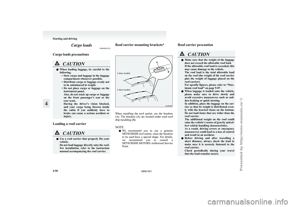
manual accompanying the roof carrier. Roof carrier mounting brackets*
3-door models
5-door models
When installing the roof carrier, use the brackets
(A). The
brackets
(A) are located under each roof
drip moulding (B).
NOTE
l We recommend you to use a genuine
MITSUBISHI roof carrier, since the brackets
to be used have a special shape. For details,
we recommend you to consult a
MITSUBISHI MOTORS Authorized Service
Point. Roof carrier precaution CAUTION
l
Make sure
that
the weight of the luggage
does not exceed the allowable roof load.
If the allowable roof load is exceeded, this
may cause damage to the vehicle.
The roof load is the total allowable load
on the roof (the weight of the roof carrier
plus the weight of luggage placed on the
roof carrier).
For specific figures, please refer to “Max-
imum roof load” on page 9-07 .
l When luggage is loaded onto the vehicle,
please make sure to drive slowly and
avoid excessive manoeuvres such as sud-
den braking or quick turning.
In addition, place the luggage on the car-
rier so that its weight is distributed even-
ly with the heaviest items on the bottom.
Do not load items that are wider than the
roof carrier.
The additional weight on the roof could
raise the vehicle’s centre of gravity and af-
fect vehicle handling characteristics.
As a result, driving errors or emergency
manoeuvres could lead to a loss of control
and result in an accident.
l Before driving and after travelling a
short distance, always check the load to
make sure it is securely fastened to the
roof carrier.
Check periodically during your travel
that the load remains secure. Starting and driving
4-56
4
OBKE12E1
Page 182 of 377
NOTE
l To
prevent wind
noise or reduction in fuel
economy, remove the roof carrier when not
in use.
l Before using an automatic car wash, remove
the roof carrier.
l Be sure that adequate clearance is main-
tained for raising the sunroof (if so equip-
ped) when installing a roof carrier. Trailer towing
E00610000550
In order
to
tow a trailer with your vehicle, when hav-
ing a trailer towing device mounted that meets all
relevant regulations in your area, consult a
MITSUBISHI MOTORS Authorized Service Point.
The regulations concerning the towing of a trailer
may differ from country to country. You are ad-
vised to obey the regulations in each area. CAUTION
l
Danger of Accident!
A towing
bar
should be fitted according
to MITSUBISHI MOTORS guidelines.
When you are going to tow a trailer,
move the transfer shift lever to “4H” posi-
tion.
Selecting the “2H” drive may increase the
differential oil temperature, resulting in
possible damage to the driving system.
Further, the drive train will be subjected
to excessive loading possibly leading to oil
leakage, component seizure, or other seri-
ous faults.
Maximum towable weight with brake
and maximum trailer-nose weight
Never exceed the
maximum towable weight with
brake and the maximum trailer-nose weight as lis-
ted in the specifications. (Refer to “Vehicle
weight” on page 9-07 .)
If you tow a trailer at an altitude of more than
1,000 m above sea-level, reduce your weight by
10 % of the gross combination weight for every in-
crease of 1,000 m above sea-level, as the engine out-
put is lowered owing to decrease in atmospheric
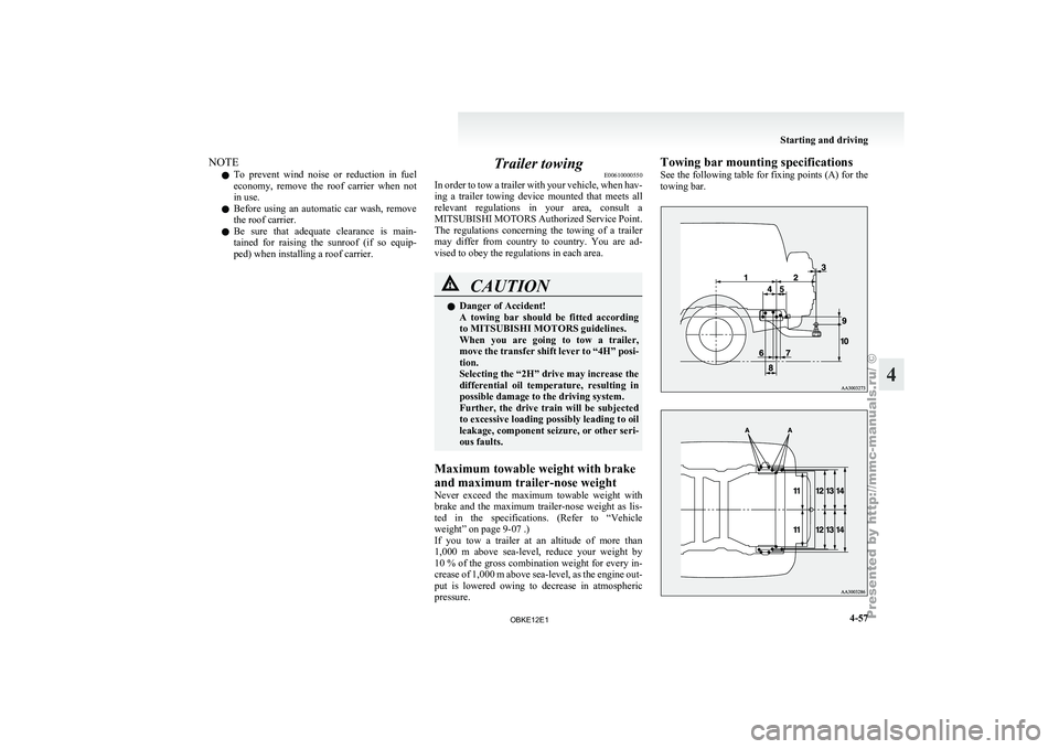
pressure. Towing bar mounting specifications
See
the following
table for fixing points (A) for the
towing bar. Starting and driving
4-57 4
OBKE12E1
Page 183 of 377
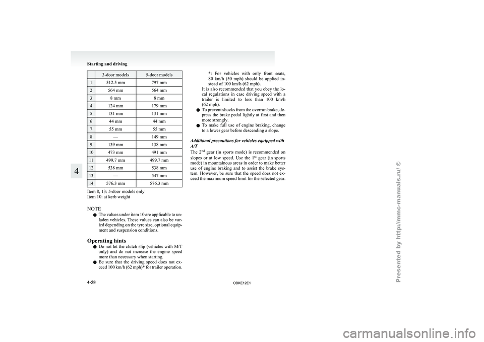
3-door models 5-door models
1 512.5 mm
797 mm2 564 mm
564 mm3 8 mm
8 mm4 124 mm
179 mm5 131 mm
131 mm6 44 mm
44 mm7 55 mm
55 mm8 —
149 mm9 139 mm
138 mm10 473 mm
491 mm11 499.7 mm
499.7 mm12 538 mm
538 mm13 —
547 mm14 576.3 mm
576.3 mmItem 8, 13: 5-door models only
Item 10: at kerb weight
NOTE
l The
values under
item 10 are applicable to un-
laden vehicles. These values can also be var-
ied depending on the tyre size, optional equip-
ment and suspension conditions.
Operating hints l Do not let the clutch slip (vehicles with M/T
only) and do not increase the engine speed
more than necessary when starting.
l Be sure that the driving speed does not ex-
ceed 100 km/h (62 mph)* for trailer operation. *: For vehicles with only front seats,
80
km/h
(50
mph) should be applied in-
stead of 100 km/h (62 mph).
It is also recommended that you obey the lo-
cal regulations in case driving speed with a
trailer is limited to less than 100 km/h
(62 mph).
l To prevent shocks from the overrun brake, de-
press the brake pedal lightly at first and then
more strongly.
l To make full use of engine braking, change
to a lower gear before descending a slope.
Additional precautions for vehicles equipped with
A/T
The 2 nd
gear (in sports mode) is recommended on
slopes or at low speed. Use the 1 st
gear (in sports
mode) in mountainous areas in order to make better
use of engine braking and to assist the brake sys-
tem. However, be sure that the speed does not ex-
ceed the maximum speed limit for the selected gear. Starting and driving
4-58
4
OBKE12E1
Page 184 of 377
Ventilators
.................................................................................... 5-02
Front automatic air conditioning ..................................................5-03
Rear air conditioning* .................................................................. 5-10
Important operation tips for the air conditioning.......................... 5-11
Air purifier (with deodorizing function) .......................................5-12
LW/MW/FM electronic tuning radio with CD player* ................5-12
LW/MW/FM electronic tuning radio with CD autoch- anger*
....................................................................................... 5-26
To play tracks from USB device* ................................................5-43
To play tracks from a Bluetooth ®
device (vehicles with
Bluetooth ®
2.0 interface).......................................................... 5-53
To use the external audio input function* ....................................5-56
To listen to a disc in the rear-seat display (vehicles with rear-seat display) .............................................................. 5-57
Steering wheel remote control switch* ........................................5-57
Error codes.................................................................................... 5-59
Error codes (iPod)......................................................................... 5-61
Error codes (USB memory device) ..............................................5-63
Handling of compact discs ........................................................... 5-65
Antenna......................................................................................... 5-66
Link System* ................................................................................ 5-67
Bluetooth ®
2.0 interface* ............................................................. 5-67
USB input terminal* ..................................................................... 5-82
Sun visors..................................................................................... 5-84
Ashtray*........................................................................................ 5-85
Cigarette lighter* .......................................................................... 5-86
Accessory socket.......................................................................... 5-86
Interior lamps ................................................................................5-87
Storage spaces............................................................................... 5-91
Cup holder.................................................................................... 5-94 Rear shelf (3-door models)*
......................................................... 5-95
Cargo area cover (5-door models)* ..............................................5-96
Convenient hooks (5-door models)* ............................................5-96
Luggage hooks.............................................................................. 5-97
Coat hooks.................................................................................... 5-97
Installation position for warning triangle .....................................5-98For pleasant driving
5
OBKE12E1
Page 185 of 377
Ventilators
E00700100373
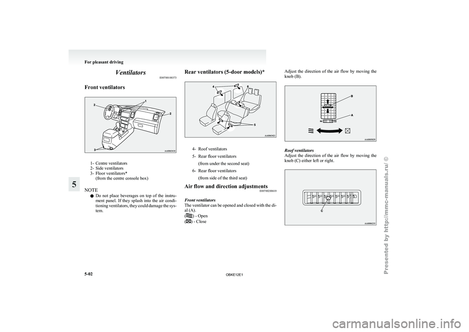
Front ventilators 1- Centre ventilators
2- Side ventilators
3-
Floor ventilators*
(from the centre console box)
NOTE l Do
not place beverages on top of the instru-
ment panel. If they splash into the air condi-
tioning ventilators, they could damage the sys-
tem. Rear ventilators (5-door models)*
4- Roof ventilators
5- Rear floor ventilators
(from under the second seat)
6- Rear floor ventilators (from side of the third seat)
Air flow and direction adjustments E00700200619
Front ventilators
The ventilator can
be opened and closed with the di-
al (A).
( ) - Open
( ) - CloseAdjust the direction of the air flow by moving the
knob (B).
Roof ventilators
Adjust the
direction
of the air flow by moving the
knob (C) either left or right. For pleasant driving
5-02
5
OBKE12E1
Page 186 of 377
NOTE
l The
cool air
from the ventilators may appear
as a mist.
This is due to moist air being suddenly
cooled by the air conditioning. This will
clear after a few moments. Front automatic air conditioning
E00702400165
The front
air
conditioning can only be used while
the engine is running. For pleasant driving
5-03 5
OBKE12E1
Page 187 of 377
Control panel
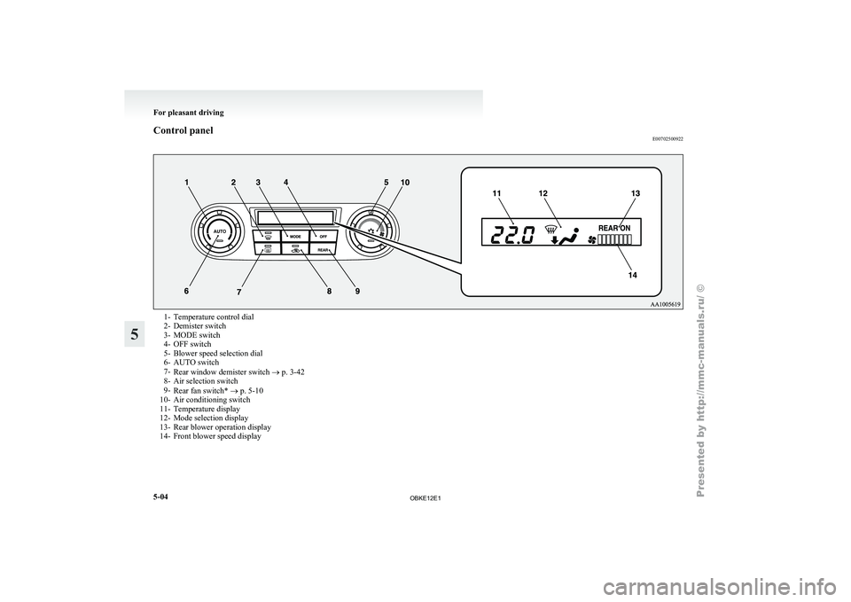
E007025009221- Temperature control dial
2- Demister switch
3-
MODE switch
4-
OFF switch
5- Blower speed selection dial
6- AUTO switch
7- Rear window demister switch ® p. 3-42
8- Air selection switch
9- Rear fan switch* ® p. 5-10
10- Air conditioning switch
11- Temperature display
12- Mode selection display
13- Rear blower operation display
14- Front blower speed display For pleasant driving
5-04
5
OBKE12E1
Page 188 of 377
NOTE
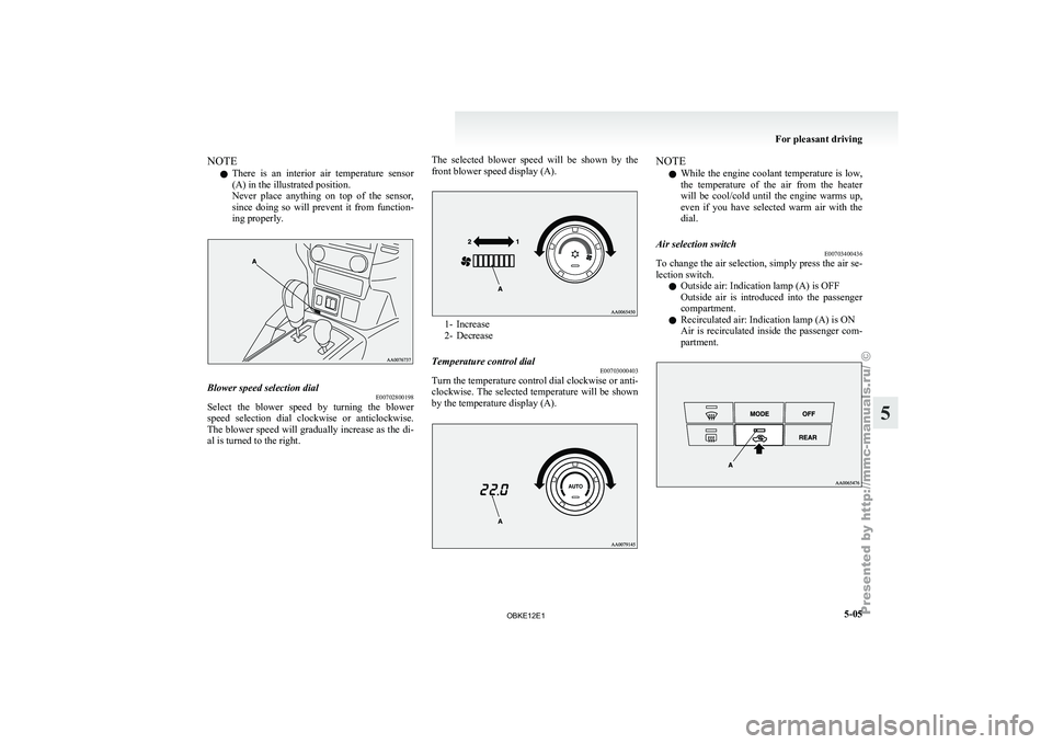
l There
is an
interior air temperature sensor
(A) in the illustrated position.
Never place anything on top of the sensor,
since doing so will prevent it from function-
ing properly. Blower speed selection dial
E00702800198
Select the blower speed by turning the blower
speed selection dial
clockwise or anticlockwise.
The blower speed will gradually increase as the di-
al is turned to the right. The selected blower speed will be shown by the
front blower speed display (A). 1- Increase
2- Decrease
Temperature control dial E00703000403
Turn the temperature control dial clockwise or anti-
clockwise. The selected
temperature will be shown
by the temperature display (A). NOTE
l While
the engine
coolant temperature is low,
the temperature of the air from the heater
will be cool/cold until the engine warms up,
even if you have selected warm air with the
dial.
Air selection switch E00703400436
To change the air selection, simply press the air se-
lection switch.
l Outside air: Indication lamp (A) is OFF
Outside
air
is
introduced into the passenger
compartment.
l Recirculated air: Indication lamp (A) is ON
Air is recirculated inside the passenger com-
partment. For pleasant driving
5-05 5
OBKE12E1
Page 189 of 377
CAUTION
l
Normally, use the outside position to keep
the windscreen and
side windows clear
and quickly remove fog or frost from the
windscreen.
If high cooling performance is desired, or
if the outside air is dusty or otherwise con-
taminated use the recirculation position.
Switch to the outside position periodically
to increase ventilation so that the win-
dows do not become fogged up.
l Use of the recirculation position for exten-
ded time may cause the windows to fog up.
NOTE l If
you press
the AUTO switch to select auto-
matic control after manually switching be-
tween outside air and recirculated air, the air
selection will also be automatically controlled. AUTO switch
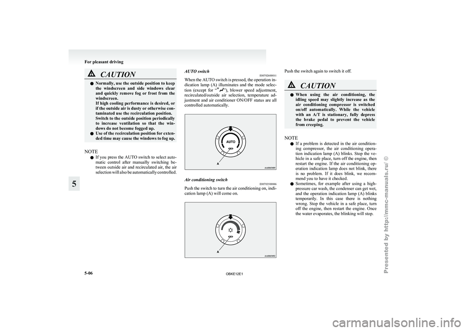
E00702600011
When the
AUTO
switch is pressed, the operation in-
dication lamp (A) illuminates and the mode selec-
tion (except for “ ”), blower speed adjustment,
recirculated/outside air
selection, temperature ad-
justment and air conditioner ON/OFF status are all
controlled automatically. Air conditioning switch
E00703500886
Push the switch to turn the air conditioning on, indi-
cation lamp (A) will come on. Push the switch again to switch it off.
CAUTION
l
When using
the air conditioning, the
idling speed may slightly increase as the
air conditioning compressor is switched
on/off automatically. While the vehicle
with an A/T is stationary, fully depress
the brake pedal to prevent the vehicle
from creeping.
NOTE l If
a problem
is detected in the air condition-
ing compressor, the air conditioning opera-
tion indication lamp (A) blinks. Stop the ve-
hicle in a safe place, turn off the engine, then
restart the engine. If the air conditioning op-
eration indication lamp does not blink, there
is no problem. If it does blink, we recom-
mend you to have it checked.
l Sometimes, for example after using a high-
pressure car wash, the condenser can get wet,
and the operation indication lamp (A) blinks
temporarily. In this case there is nothing
wrong. Stop the vehicle in a safe place, turn
off the engine, then restart the engine. Once
the water evaporates, the blinking will stop. For pleasant driving
5-06
5
OBKE12E1
Page 190 of 377
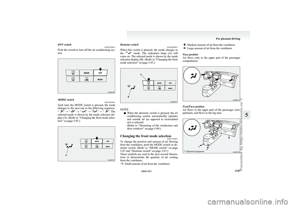
OFF switch
E00702700012
Push the switch
to turn off the air conditioning sys-
tem. MODE switch
E00703300015
Each time the MODE switch is pressed, the mode
changes to the
next one in the following sequence:
“ ” → “ ” → “ ” → “ ” → “ ”. The
selected mode
is shown by the mode selection dis-
play (A). (Refer to “Changing the front mode selec-
tion” on page 5-07.) Demister switch
E00703900037
When this switch
is pressed, the mode changes to
the “ ” mode. The indication lamp (A) will
come on.
The selected mode is shown by the mode
selection display (B). (Refer to “Changing the front
mode selection” on page 5-07.) NOTE
l When
the demister
switch is pressed, the air
conditioning system automatically operates
and outside air (as opposed to recirculated
air) is selected.
(Refer to “Demisting of the windscreen and
door windows” on page 5-09.)
Changing the front mode selection E00727100017
To change the position and amount of air flowing
from the ventilators,
push the MODE switch or de-
mister switch. (Refer to “MODE switch” on page
5-07 and “Demister switch” on page 5-07.)
These symbols are used in the next several illustra-
tions to demonstrate the quantity of air coming
from the ventilators. : Small amount of air from the ventilators : Medium amount of air from the ventilators
: Large amount of air from the ventilators
Face position
Air flows only
to the upper part of the passenger
compartment. Foot/Face position
Air
flows to
the upper part of the passenger com-
partment, and flows to the leg area.
*: Optional equipment For pleasant driving
5-07 5
OBKE12E1