engine MITSUBISHI SHOGUN 2003 Owner's Manual (in English)
[x] Cancel search | Manufacturer: MITSUBISHI, Model Year: 2003, Model line: SHOGUN, Model: MITSUBISHI SHOGUN 2003Pages: 392, PDF Size: 14.34 MB
Page 349 of 392
During cold weatherThe capacity of the battery is reduced at
low temperatures. This is an inevitable
result of its chemical and physical proper-
ties. This is why a very cold battery, par-
ticularly one that is not fully charged
anyway, will only deliver a fraction of the
starter current which is normally avail-
able.
It is recommended that you have the bat-
tery checked by an authorized
MITSUBISHI dealer before the start of cold
weather and, if necessary, have it charged.
This not only ensures reliable starting, but
a battery which is kept fully charged also
has a longer life.Disconnection and connectionTo disconnect the battery cable, stop the
engine, first disconnect the negative (-) ter-
minal and then the positive (+) terminal.
When connecting the battery, first con-
nect the positive (+) terminal and then the
negative (-) terminal.
WARNING
(1) Keep sparks, cigarettes, and
flames away from the battery
because the battery could
explode.
(2) The battery electrolyte is
extremely caustic. Do not allow
it to come in contact with your
eyes, skin, clothing, or the
painted surfaces of the vehicle.
Spilled electrolyte should be
flushed immediately with ample
amounts of water.
Irritation to eyes or skin from
contact with electrolyte requires
immediate medical attention.
(3) Ventilate when charging or using
the battery in an enclosed space.
CAUTION
(1) Never disconnect the battery
with the ignition switch in the
“ON” position; doing so could
damage the vehicle’s electrical
components.
(2) Never short-circuit the battery;
doing so could cause it to over-
heat and be damaged.
(3) Always wear protective eye
goggles when working near the
battery.
CAUTION
(4) If the battery is to be quick-
charged, first disconnect the bat-
tery cables.
(5) In order to prevent a short cir-
cuit, be sure to disconnect the
negative (-) terminal first.
(6) Keep it out of reach of chil-
dren.
NOTE
(1) Keep the terminals clean. After the bat-
tery is connected, apply terminal pro-
tection grease. To clean the terminals,
use lukewarm water.
(2) Check to see if the battery is securely
installed and cannot be moved dur-
ing travel. Also check each terminal for
tightness.
(3) When the vehicle is to be left unused
for a long period of time, remove the
battery and store it in a place where the
battery fluid will not freeze. The bat-
tery should be stored only in a fully
charged condition.
Maintenance
9-7
Div:
Out put date:
Page 351 of 392
WARNING
(1) Take care in handling brake fluid
as it is harmful to the eyes and
may also cause damage to
painted surfaces. If fluid is
spilled, wipe it up as soon as
possible.
(2) Use only the specified brake
fluid.
Also, the additives in different
brands may result in a chemi-
cal reaction when mixed
together, so avoid mixing differ-
ent brands if possible.
(3) Normally, keep the reservoir tank
cap closed to prevent the brake
fluid from deteriorating.
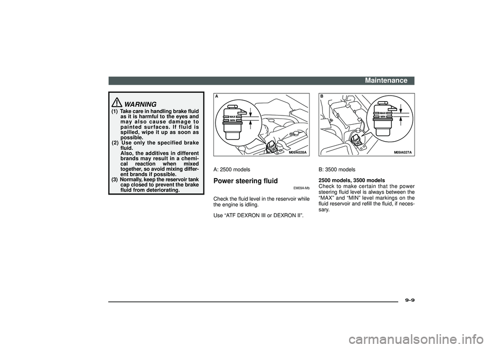
M09A028A
AA: 2500 modelsPower steering fluid
EM09A-Mb
Check the fluid level in the reservoir while
the engine is idling.
Use“ATF DEXRON III or DEXRON II”.
M09A027A
BB: 3500 models
2500 models, 3500 models
Check to make certain that the power
steering fluid level is always between the
“MAX”and“MIN”level markings on the
fluid reservoir and refill the fluid, if neces-
sary.
Maintenance
9-9
Div:
Out put date:
Page 359 of 392
CAUTION
(1) If your vehicle is equipped with
anti-lock brake system (ABS), in
order to ensure that the anti-lock
brake system (ABS) will oper-
ate correctly in situations where
tyre chains have been fitted,
drive in“4H”or“4L”for part
time 4WD, or in“4H”,“4HLc”or
“4LLc”for super select 4WD.
(2) Practice fitting the chains before
you need them. Don’t expect
help from other people in the
cold.
(3) Choose a clear straight stretch of
road where you can pull off and
still be seen while you are fit-
ting the chains.
(4) Do not fit chains before you need
them. This will wear out your
tyres and the road surface.
(5) After driving around 100-300
metres, stop and retighten the
chains.
(6) Care should be taken with
extremes of steering lock to pre-
vent possible contact between
the chains and the vehicle body.
(7) Drive carefully and do not
exceed 50 km/h (31 mph).
Remember, fitting chains is not
going to stop accidents from
happening.
CAUTION
( 8) When tyre chains are installed,
take care that they do not dam-
age the disc wheel or body.
( 9) An aluminium wheel can be
damaged by a tyre chain while
driving. When fitting a tyre
chain on an aluminium wheel,
take care that no part of the
chain and fitting can be
brought into contact with the
wheel disc.
(10) When installing or removing a
tyre chain, take care that hands
and other parts of your body
are not injured by the sharp
edges of the vehicle body.
(11) Install the chains only on the
rear tyres and tighten them as
tightly as possible with the
ends securely fastened.
NOTE
The laws and regulations concerning the
use of tyre chains vary. Find out and fol-
low the laws and regulations in your driv-
ing area.
In most countries, it is prohibited by law to
use tyre chains on roads without snow.
Fuel, engine coolant, oil and
exhaust gas leakage
EM14A-BD
Look under the body of your vehicle to
check for fuel, engine coolant, oil and
exhaust gas leaks.
WARNING
If you see a suspicious fuel leak or if
you smell fuel, do not operate the
vehicle; call your authorized MITSUB-
ISHI dealer for assistance.
Maintenance
9-17
Div:
Out put date:
Page 360 of 392
Exterior and interior lamp
operation
EM35A-Ad
Operate the combination lamp switch to
check that all lamps are functioning prop-
erly.
If the lamps do not illuminate, the prob-
able cause is a blown fuse or defective
lamp bulb. Check the fuses first. If there is
no blown fuse, check the lamp bulbs.
For information regarding the inspection
and replacement of the fuses and the lamp
bulbs, refer to the section entitled“For
emergencies”.
If the fuses and bulbs are all OK, take the
vehicle to an authorized MITSUBISHI
dealer for inspection and repair.Meter, gauge and indication
/warning lamp operationRun the engine to check the operation of
all meters, gauges, and indication /warning
lamps.
If there is anything wrong, take the vehicle
to an authorized MITSUBISHI dealer for
inspection.
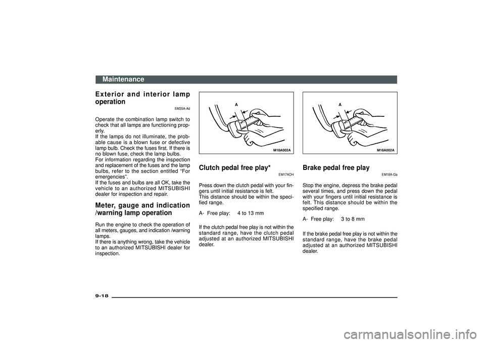
M18A002A
A
Clutch pedal free play*
EM17AOH
Press down the clutch pedal with your fin-
gers until initial resistance is felt.
This distance should be within the speci-
fied range.
A- Free play: 4 to 13 mm
If the clutch pedal free play is not within the
standard range, have the clutch pedal
adjusted at an authorized MITSUBISHI
dealer.
M18A002A
A
Brake pedal free play
EM18A-Ga
Stop the engine, depress the brake pedal
several times, and press down the pedal
with your fingers until initial resistance is
felt. This distance should be within the
specified range.
A- Free play: 3 to 8 mm
If the brake pedal free play is not within the
standard range, have the brake pedal
adjusted at an authorized MITSUBISHI
dealer.
Maintenance
9-18Div:
Out put date:
Page 365 of 392
Specifications
Chassis number .......................................... 10- 2
Engine number ............................................ 10- 2
Vehicle identification number plate
(RHD vehicles only)................................. 10- 3
Vehicle information code plate .................. 10- 3
Dimensions ................................................. 10- 6
Performance ................................................ 10- 7
Weight .......................................................... 10- 7
Engine .......................................................... 10- 9
Transmission ............................................... 10- 9
Electrical system......................................... 10-10
Tyres and wheels ........................................ 10-10
Other specifications.................................... 10-11
Fuel consumption ...................................... 10-12
Notes regarding diesel fuel........................ 10-14
Capacities .................................................... 10-16
Div:
Out put date:
Page 366 of 392
B02A026A
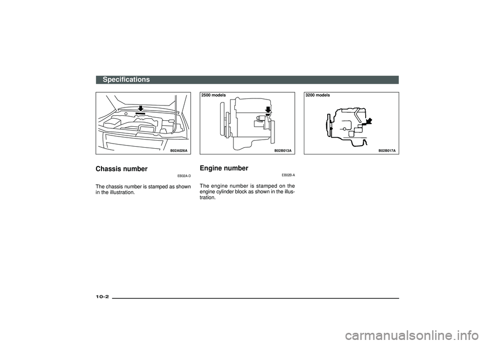
Chassis number
EB02A-D
The chassis number is stamped as shown
in the illustration.
B02B013A
2500 modelsEngine number
EB02B-A
The engine number is stamped on the
engine cylinder block as shown in the illus-
tration.
B02B017A
3200 models
Specifications
10-2Div:
Out put date:
Page 367 of 392
B02B014A
3500 models
B02C086A
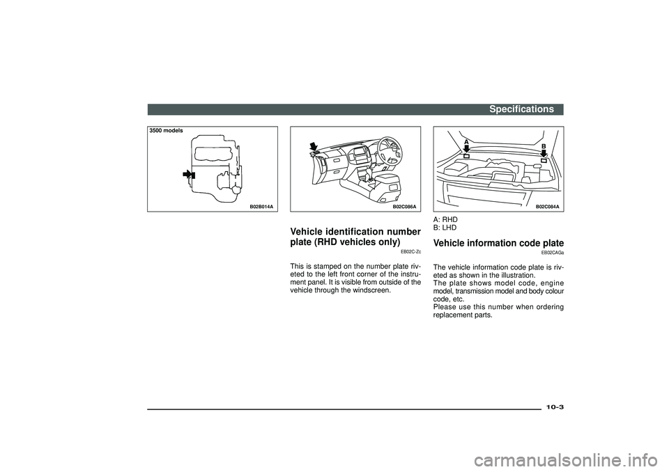
Vehicle identification number
plate (RHD vehicles only)
EB02C-Zc
This is stamped on the number plate riv-
eted to the left front corner of the instru-
ment panel. It is visible from outside of the
vehicle through the windscreen.
B02C084A
A: RHD
B: LHDVehicle information code plate
EB02CAGa
The vehicle information code plate is riv-
eted as shown in the illustration.
The plate shows model code, engine
model, transmission model and body colour
code, etc.
Please use this number when ordering
replacement parts.
Specifications
10-3
Div:
Out put date:
Page 368 of 392
B02C066A
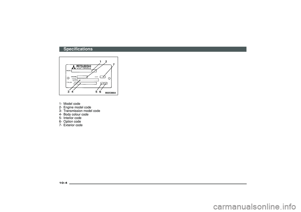
1- Model code
2- Engine model code
3- Transmission model code
4- Body colour code
5- Interior code
6- Option code
7- Exterior code
Specifications
10-4Div:
Out put date:
Page 373 of 392
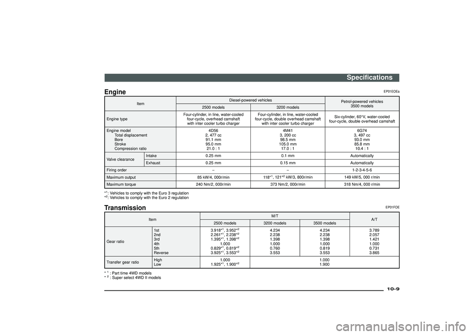
Engine
EP01EOEa
ItemDiesel-powered vehicles
Petrol-powered vehicles
3500 models
2500 models 3200 models
Engine typeFour-cylinder, in line, water-cooled
four-cycle, overhead camshaft
with inter cooler turbo chargerFour-cylinder, in line, water-cooled
four-cycle, double overhead camshaft
with inter cooler turbo chargerSix-cylinder, 60°V, water-cooled
four-cycle, double overhead camshaft
Engine model
Total displacement
Bore
Stroke
Compression ratio4D56
2, 477 cc
91.1 mm
95.0 mm
21.0 : 14M41
3, 200 cc
98.5 mm
105.0 mm
17.0 : 16G74
3, 497 cc
93.0 mm
85.8 mm
10.4 : 1
Valve clearanceIntake 0.25 mm 0.1 mm Automatically
Exhaust 0.25 mm 0.15 mm Automatically
Firing order−−1-2-3-4-5-6
Maximum output 85 kW/4, 000r/min 118*
1, 121*
2kW/3, 800r/min 149 kW/5, 000 r/min
Maximum torque 240 Nm/2, 000r/min 373 Nm/2, 000r/min 318 Nm/4, 000 r/min
*
1: Vehicles to comply with the Euro 3 regulation
*2: Vehicles to comply with the Euro 2 regulationTransmission
EP01FOE
ItemM/T
A/T
2500 models 3200 models 3500 models
Gear ratio1st
2nd
3rd
4th
5th
Reverse3.918*
1, 3.952*
2
2.261*
1, 2.238*
2
1.395*
1, 1.398*
2
1.000
0.829*1, 0.819*
2
3.925*
1, 3.553*
2
4.234
2.238
1.398
1.000
0.760
3.5534.234
2.238
1.398
1.000
0.819
3.5533.789
2.057
1.421
1.000
0.731
3.865
Transfer gear ratioHigh
Low1.000
1.925*
1, 1.900*
2
1.000
1.900
*
1: Part time 4WD models
*2: Super select 4WD II models
Specifications
10-9
Div:
Out put date:
Page 380 of 392
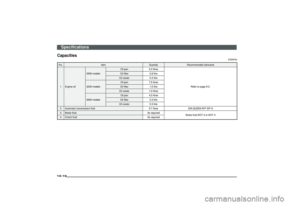
Capacities
EQ02AOIc
N o . Item Quantity Recommended lubricants1 Engine oil 2500 models
Oil pan 6.3 litres
Refer to page 9-2.
Oil filter 0.8 litre
Oil cooler 0.3 litre
3200 models Oil pan 7.5 litres
Oil filter 1.0 litre
Oil cooler 1.3 litres
3500 models Oil pan 4.3 litres
Oil filter 0.3 litre
Oil cooler 0.3 litre
2 Automatic transmission fluid 9.7 litres DIA QUEEN ATF SP III
3 Brake fluid As required Brake fluid DOT 3 or DOT 4
4 Clutch fluid As requiredSpecifications
10-16Div:
Out put date: