engine MITSUBISHI SHOGUN 2003 (in English) Manual Online
[x] Cancel search | Manufacturer: MITSUBISHI, Model Year: 2003, Model line: SHOGUN, Model: MITSUBISHI SHOGUN 2003Pages: 392, PDF Size: 14.34 MB
Page 300 of 392
If the vehicle breaks down
EN40B-Bc
If the vehicle breaks down on the road,
move it to the shoulder and use the haz-
ard warning flashers.If the engine stops/failsVehicle operation and control are affected
if the engine stops. Before moving the
vehicle to a safe area be aware of the
following:
1. The brake booster becomes inopera-
tive and the pedal effort will increase.
Press down the brake pedal harder than
usual.
2. Since the power steering pump is no
longer operative, the steering wheel
feels heavy when turning it. Turn the
wheel with more effort than usual.
Operation under adverse driv-
ing conditions
EI43AAKa
If your vehicle is stuck in sand, mud
or snowIf the vehicle becomes stuck in snow, sand,
or mud, it can often be moved with a rock-
ing motion. Move the selector lever alter-
nately between the Sports-mode and “R”
(REVERSE) position (with manual trans-
mission, between 1st and Reverse), while
applying slight pressure to the accelera-
tor pedal.
Avoid racing the engine or spinning the
wheels. Prolonged efforts to free a stuck
vehicle may result in overheating and trans-
mission failure. Allow the engine to idle for
a few minutes to let the transmission cool
between rocking attempts.
If the vehicle remains stuck after several
rocking attempts, seek other assistance.
WARNING
When attempting to rock your vehicle
out of a stuck position, be sure that
the area around the vehicle is clear of
people and physical objects. The
rocking motion may cause the
vehicle to suddenly launch forward
or backward, causing injury or dam-
age to nearby people or objects.
For emergencies
8-2Div:
Out put date:
Page 309 of 392
NOTE
Take care when lowering the vehicle, as
sudden closure of the jack release valve
can cause damage to the jack.
3. Remove the jack.
NOTE
(1) Occasionally, when the vehicle is
raised, the grooved portion of the ram
will not disengage. When this hap-
pens, rock the vehicle to lower the ram.
(2) When the jack is difficult to remove by
hand, insert the jack handle into the
holder and hook the jack handle notch
onto the holder notch and secure it
there. Then pull the jack handle and
remove the jack.
4. Press the piston down all the way, and
turn the release valve clockwise as far
as possible.
5. Store the jack and jack handle.
WARNING
(1) Raise the vehicle so the tyre just
clears the ground. It is danger-
ous to raise the vehicle any
higher.
(2) Never get under the vehicle while
using the jack. Avoid jarring the
raised vehicle or leaving it sup-
ported on the jack for any longer
than required. Both are very
dangerous.
(3) Do not start or run the engine
while the vehicle is on the jack.
The vehicle might start moving
causing the vehicle to fall down
from the jack.
(4) Do not turn the jacked up
wheels. The tyres remaining on
the ground may turn, causing
the vehicle body to fall down
from the jack.
(5) No one should stay in the vehicle
while the jack is used.
CAUTION
Use only the jack included with the
vehicle, and use it only for chang-
ing wheels.
N03A358A
Spare wheel
EN23A-N
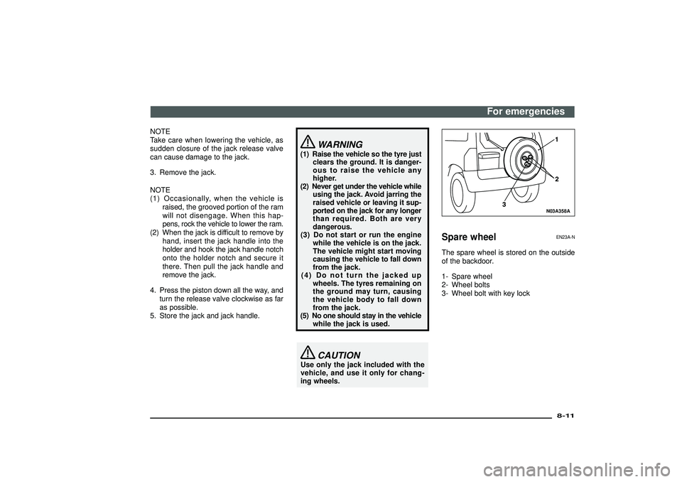
The spare wheel is stored on the outside
of the backdoor.
1- Spare wheel
2- Wheel bolts
3- Wheel bolt with key lock
For emergencies
8-11
Div:
Out put date:
Page 317 of 392
N25A336A
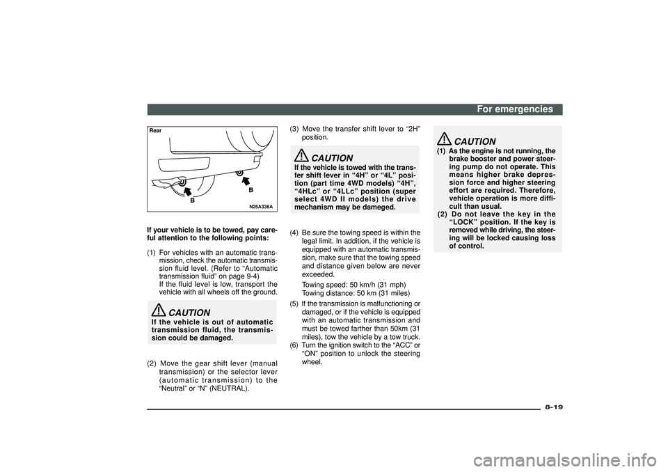
RearIf your vehicle is to be towed, pay care-
ful attention to the following points:
(1) For vehicles with an automatic trans-
mission, check the automatic transmis-
sion fluid level. (Refer to“Automatic
transmission fluid”on page 9-4)
If the fluid level is low, transport the
vehicle with all wheels off the ground.
CAUTION
If the vehicle is out of automatic
transmission fluid, the transmis-
sion could be damaged.
(2) Move the gear shift lever (manual
transmission) or the selector lever
(automatic transmission) to the
“Neutral”or“N”(NEUTRAL).(3) Move the transfer shift lever to“2H”
position.
CAUTION
If the vehicle is towed with the trans-
fer shift lever in“4H”or“4L”posi-
tion (part time 4WD models)“4H”,
“4HLc”or“4LLc”position (super
select 4WD II models) the drive
mechanism may be dameged.
(4) Be sure the towing speed is within the
legal limit. In addition, if the vehicle is
equipped with an automatic transmis-
sion, make sure that the towing speed
and distance given below are never
exceeded.
Towing speed: 50 km/h (31 mph)
Towing distance: 50 km (31 miles)
(5) If the transmission is malfunctioning or
damaged, or if the vehicle is equipped
with an automatic transmission and
must be towed farther than 50km (31
miles), tow the vehicle by a tow truck.
(6) Turn the ignition switch to the“ACC”or
“ON”position to unlock the steering
wheel.
CAUTION
(1) As the engine is not running, the
brake booster and power steer-
ing pump do not operate. This
means higher brake depres-
sion force and higher steering
effort are required. Therefore,
vehicle operation is more diffi-
cult than usual.
(2) Do not leave the key in the
“LOCK”position. If the key is
removed while driving, the steer-
ing will be locked causing loss
of control.
For emergencies
8-19
Div:
Out put date:
Page 319 of 392
![MITSUBISHI SHOGUN 2003 (in English) Manual Online CAUTION
[For super select 4WD II]
When you are going to tow another
vehicle, move the transfer shift lever
to“4H”position.
Selecting“2H”drive may increase
the differential oil temperature, res MITSUBISHI SHOGUN 2003 (in English) Manual Online CAUTION
[For super select 4WD II]
When you are going to tow another
vehicle, move the transfer shift lever
to“4H”position.
Selecting“2H”drive may increase
the differential oil temperature, res](/img/19/34883/w960_34883-318.png)
CAUTION
[For super select 4WD II]
When you are going to tow another
vehicle, move the transfer shift lever
to“4H”position.
Selecting“2H”drive may increase
the differential oil temperature, result-
ing in possible damage to the driv-
ing system.
Further, the drive train will be sub-
jected to excessive loading possi-
bly leading to oil leakage, component
seizure, or other serious faults.
NOTE
Your vehicle should only be used to tow
another vehicle if the weight of the other
vehicle is less than your vehicle.
Engine overheating
EN26AAY
If the water temperature gauge indication
remains in the overheating zone for a long
time, the engine may be overheating. If this
occurs, take the following corrective
measures:
1. Stop the vehicle in a safe place.
N26A208A
2. With the engine still running, raise the
bonnet to ventilate the engine compart-
ment.
A- Radiator cap
B- Radiator fan
C- Reserve tank
NOTE
Confirm that the radiator fan is turning. If
the fan is not turning, stop the engine
immediately and contact an authorized
MITSUBISHI dealer for assistance.
For emergencies
8-21
Div:
Out put date:
Page 320 of 392
WARNING
(1) Remember that under the bon-
net, there can be boiling water
gushing out, or the support bar
could be burning hot. If the bon-
net is opened suddenly, you
could get burnt.
(2) Be careful of hot steam, which
could be blowing off the reserve
tank cap.
(3) Do not attempt to remove the
radiator cap while the engine is
hot.
N26A209A
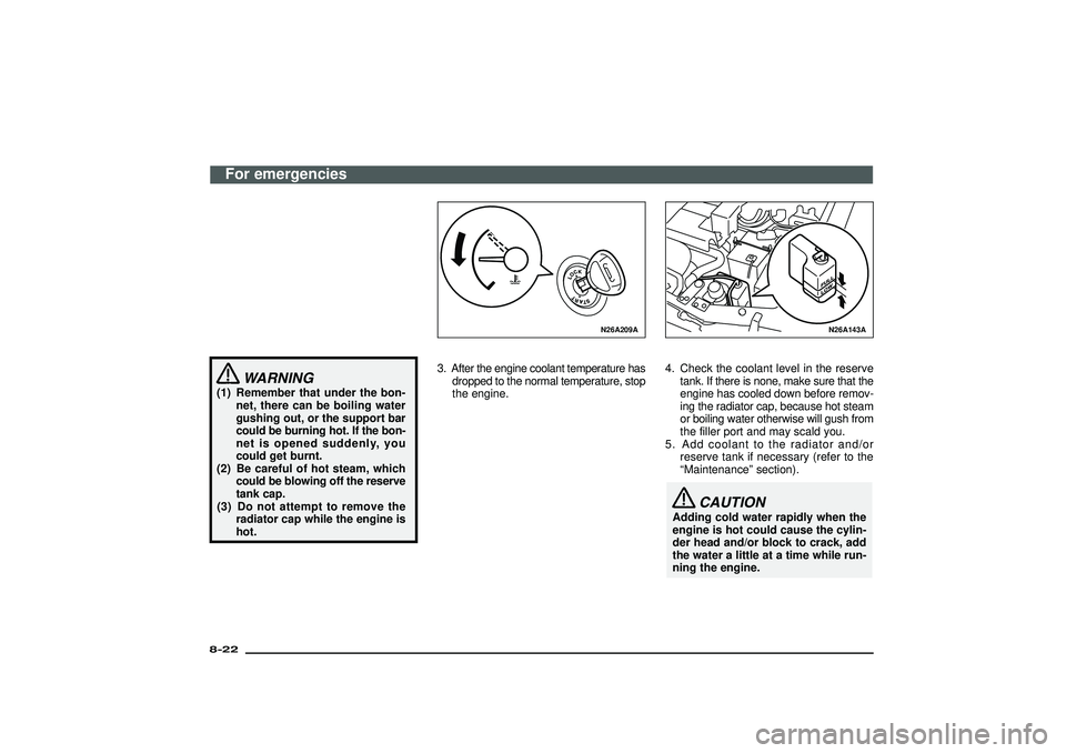
3. After the engine coolant temperature has
dropped to the normal temperature, stop
the engine.
N26A143A
4. Check the coolant level in the reserve
tank. If there is none, make sure that the
engine has cooled down before remov-
ing the radiator cap, because hot steam
or boiling water otherwise will gush from
the filler port and may scald you.
5. Add coolant to the radiator and/or
reserve tank if necessary (refer to the
“Maintenance”section).
CAUTION
Adding cold water rapidly when the
engine is hot could cause the cylin-
der head and/or block to crack, add
the water a little at a time while run-
ning the engine.
For emergencies
8-22Div:
Out put date:
Page 322 of 392
CAUTION
(1) Do not smoke or have any other
open flame near the vehicle
while bleeding the fuel system.
(2) Be sure to carefully clean away
any spilt fuel which could ignite
and cause a fire.
N07B021A
Removal of water from the fuel
filter (diesel- powered vehicles
only)
EN07B-Bc
If the warning lamp illuminates during driv-
ing, it indicates that water has accumu-
lated in the fuel filter. If this occurs, remove
the water as described below.
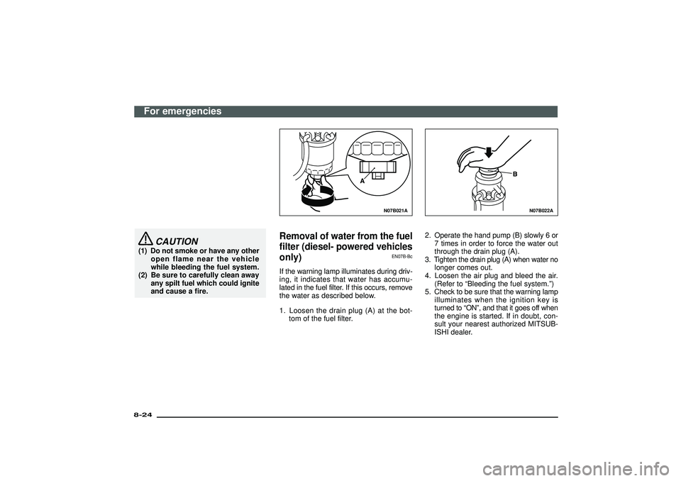
1. Loosen the drain plug (A) at the bot-
tom of the fuel filter.
N07B022A
2. Operate the hand pump (B) slowly 6 or
7 times in order to force the water out
through the drain plug (A).
3. Tighten the drain plug (A) when water no
longer comes out.
4. Loosen the air plug and bleed the air.
(Refer to“Bleeding the fuel system.”)
5. Check to be sure that the warning lamp
illuminates when the ignition key is
turned to“ON”, and that it goes off when
the engine is started. If in doubt, con-
sult your nearest authorized MITSUB-
ISHI dealer.
For emergencies
8-24Div:
Out put date:
Page 323 of 392
CAUTION
(1) Do not smoke or have any other
open flame near the vehicle
while bleeding the fuel system.
(2) Be sure to carefully clean away
any water drained out because
any fuel mixed with the water
could ignite and cause a fire.
N28A122A
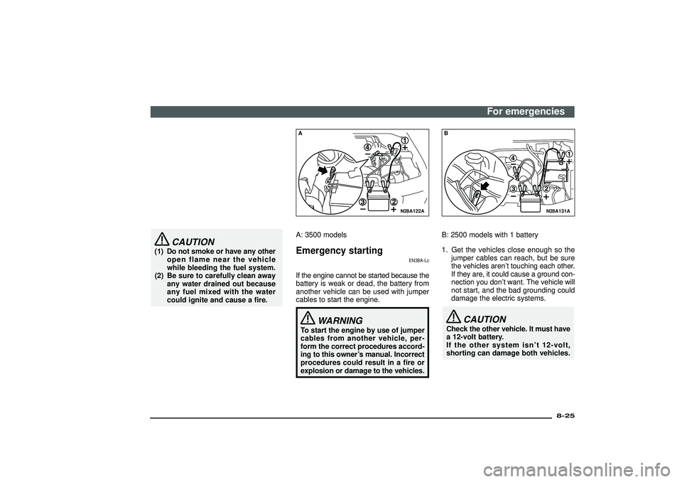
AA: 3500 modelsEmergency starting
EN38A-Lc
If the engine cannot be started because the
battery is weak or dead, the battery from
another vehicle can be used with jumper
cables to start the engine.
WARNING
To start the engine by use of jumper
cables from another vehicle, per-
form the correct procedures accord-
ing to this owner’s manual. Incorrect
procedures could result in a fire or
explosion or damage to the vehicles.
N28A131A
BB: 2500 models with 1 battery
1. Get the vehicles close enough so the
jumper cables can reach, but be sure
the vehicles aren’t touching each other.
If they are, it could cause a ground con-
nection you don’t want. The vehicle will
not start, and the bad grounding could
damage the electric systems.
CAUTION
Check the other vehicle. It must have
a 12-volt battery.
If the other system isn’t 12-volt,
shorting can damage both vehicles.
For emergencies
8-25
Div:
Out put date:
Page 324 of 392
N28A132A
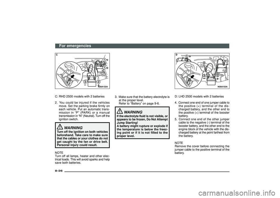
CC: RHD 2500 models with 2 batteries
2. You could be injured if the vehicles
move. Set the parking brake firmly on
each vehicle. Put an automatic trans-
mission in“P”(PARK) or a manual
transmission in“N”(Neutral). Turn off the
ignition switch.
WARNING
Turn off the ignition on both vehicles
beforehand. Take care to make sure
that the cables or your clothes do not
get caught by the fan or drive belt.
Personal injury could result.
NOTE
Turn off all lamps, heater and other elec-
trical loads. This will avoid sparks and help
save both batteries.3. Make sure that the battery electrolyte is
at the proper level.
Refer to“Battery”on page 9-6.
WARNING
If the electrolyte fluid is not visible, or
appears to be frozen, Do Not Attempt
Jump Starting!
A battery might rupture or explode if
the temperature is below the freez-
ing point or if it is not filled to the
proper level.
N28A133A
DD: LHD 2500 models with 2 batteries
4. Connect one end of one jumper cable to
the positive (+) terminal of the dis-
charged battery, and the other end to
the positive (+) terminal of the booster
battery.
5. Connect one end of the other jumper
cable to the negative (-) terminal of the
booster battery, and the other end to the
engine block of the vehicle with the dis-
charged battery at the point farthest from
the battery.
NOTE
Remove the cover before connecting the
jumper cable to the positive terminal of the
battery.
For emergencies
8-26Div:
Out put date:
Page 325 of 392
N28A172A
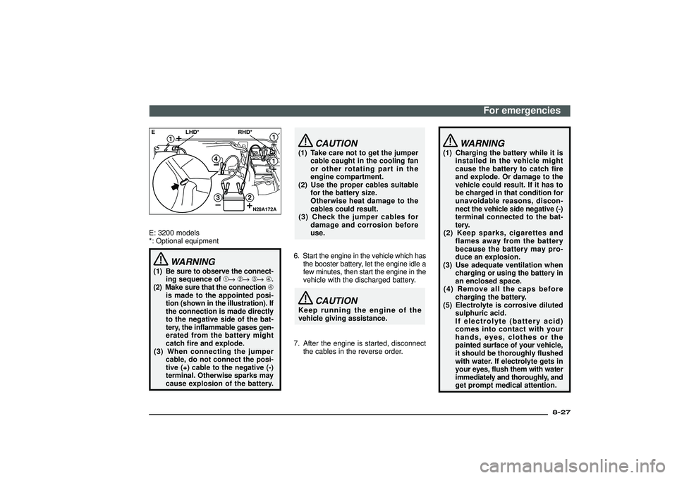
E LHD* RHD*E: 3200 models
*: Optional equipment
WARNING
(1) Be sure to observe the connect-
ing sequence of➀→➁→➂→➃.
(2) Make sure that the connection➃
is made to the appointed posi-
tion (shown in the illustration). If
the connection is made directly
to the negative side of the bat-
tery, the inflammable gases gen-
erated from the battery might
catch fire and explode.
(3)
When connecting the jumper
cable, do not connect the posi-
tive (+) cable to the negative (-)
terminal. Otherwise sparks may
cause explosion of the battery.
CAUTION
(1) Take care not to get the jumper
cable caught in the cooling fan
or other rotating part in the
engine compartment.
(2) Use the proper cables suitable
for the battery size.
Otherwise heat damage to the
cables could result.
(3) Check the jumper cables for
damage and corrosion before
use.
6. Start the engine in the vehicle which has
the booster battery, let the engine idle a
few minutes, then start the engine in the
vehicle with the discharged battery.
CAUTION
Keep running the engine of the
vehicle giving assistance.
7. After the engine is started, disconnect
the cables in the reverse order.
WARNING
(1) Charging the battery while it is
installed in the vehicle might
cause the battery to catch fire
and explode. Or damage to the
vehicle could result. If it has to
be charged in that condition for
unavoidable reasons, discon-
nect the vehicle side negative (-)
terminal connected to the bat-
tery.
(2) Keep sparks, cigarettes and
flames away from the battery
because the battery may pro-
duce an explosion.
(3) Use adequate ventilation when
charging or using the battery in
an enclosed space.
(4) Remove all the caps before
charging the battery.
(5) Electrolyte is corrosive diluted
sulphuric acid.
If electrolyte (battery acid)
comes into contact with your
hands, eyes, clothes or the
painted surface of your vehicle,
it should be thoroughly flushed
with water. If electrolyte gets in
your eyes, flush them with water
immediately and thoroughly, and
get prompt medical attention.
For emergencies
8-27
Div:
Out put date:
Page 326 of 392
CAUTION
(1) Do not attempt to start the
engine by pulling or pushing the
vehicle.
It could damage your vehicle.
(2) Always wear protective eye
goggles when working near the
battery.
(3) Keep the battery out of the reach
of children.
NOTE
On a vehicle with an anti-lock brake sys-
tem, if the vehicle is started or put in motion
without fully charging the battery, it might
cause the loss of smooth engine opera-
tion and it might cause the anti-lock brake
warning lamp to illuminate.
Refer to“Anti-lock brake system (ABS)”on
page 5-45.
What to do if the engine speed
becomes unstable after the bat-
tery is replaced
EN38B-G
If the engine speed becomes unstable after
the battery is replaced, reset the engine
using the following method:
1. Stop the vehicle in a safe place.
2. Place the gear shift lever (manual
transmission) in the“N”(Neutral) or the
selector lever (automatic transmission)
in the“P”(PARK) position.
Stop the engine.
3. Restart the engine.
4. Turn off the air conditioning.
5. Allow the engine to warm up until the
needle in the water temperature gauge
stabilizes near the centre of the gauge.
6. Stop and restart the engine.
7. Allow the engine to idle for approxi-
mately 10 minutes.
8. When the engine speed stabilizes, the
resetting procedure is complete.
NOTE
If the engine speed remains unstable after
the resetting procedure has been per-
formed, have the vehicle inspected by an
authorized MITSUBISHI dealer.
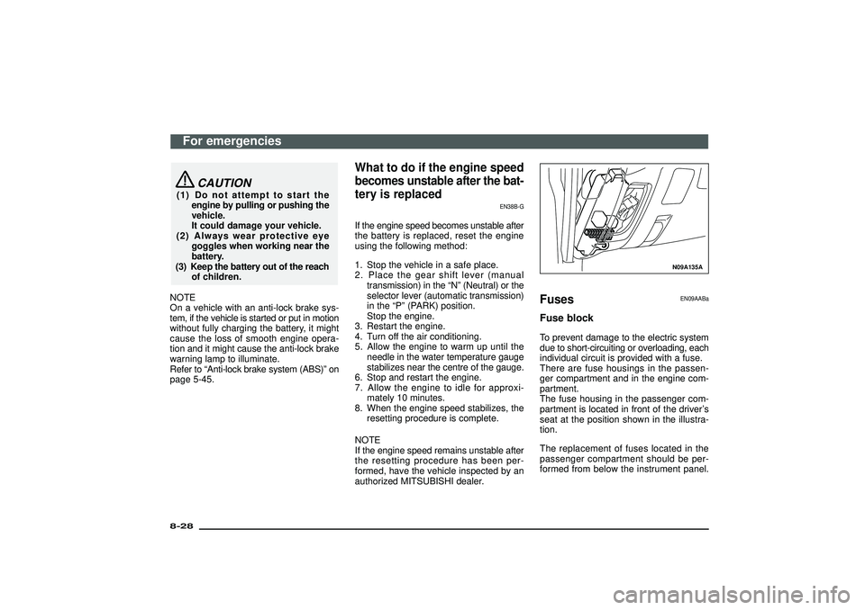
N09A135A
Fuses
EN09AABa
Fuse blockTo prevent damage to the electric system
due to short-circuiting or overloading, each
individual circuit is provided with a fuse.
There are fuse housings in the passen-
ger compartment and in the engine com-
partment.
The fuse housing in the passenger com-
partment is located in front of the driver’s
seat at the position shown in the illustra-
tion.
The replacement of fuses located in the
passenger compartment should be per-
formed from below the instrument panel.
For emergencies
8-28Div:
Out put date: