key MITSUBISHI SHOGUN 2003 (in English) Owner's Guide
[x] Cancel search | Manufacturer: MITSUBISHI, Model Year: 2003, Model line: SHOGUN, Model: MITSUBISHI SHOGUN 2003Pages: 392, PDF Size: 14.34 MB
Page 171 of 392
CAUTION
(1) Never attempt to start the engine
by pushing or pulling the
vehicle. Especially in vehicles
with the automatic transmis-
sion, it is not possible to start
the engine by using this tech-
nique since the structure is dif-
ferent from a manual
transmission. Never attempt this
or it could damage the auto-
matic transmission.
(2) Do not run the engine at high
rpm or drive the vehicle at high
speed until the engine has had a
chance to warm up.
(3) Release the ignition key as soon
as the engine starts to avoid
damaging the starter motor.
(4) If your vehicle is equipped with
a turbocharger, do not stop the
engine immediately after oper-
ating the vehicle at high speeds.
Allow the engine to idle for
approximately 60 seconds or
more to give the turbocharger a
chance to cool down.NOTE
After replacing the battery, the electronic
control system data for the engine will be
erased. As a result, the engine speed may
become unstable.
If the engine speed becomes unstable, ini-
tial engine adjustments will need to be per-
formed.
Refer to the section“What to do if the
engine speed becomes unstable after the
battery is replaced”on page 8-28.
I27A072A
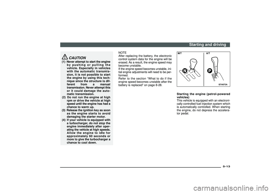
M/T A/TStarting the engine (petrol-powered
vehicles)
This vehicle is equipped with an electroni-
cally controlled fuel injection system which
is automatically controlled. When starting
the engine, do not depress the accelera-
tor pedal.
Starting and driving
5-13
Div:
Out put date:
Page 172 of 392
Normal conditions
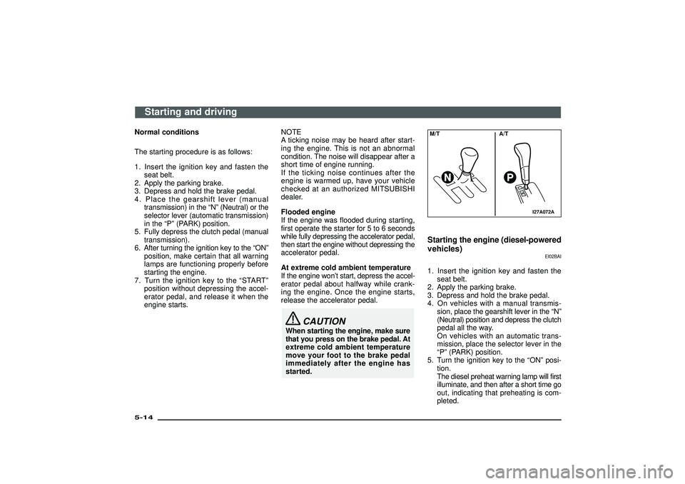
The starting procedure is as follows:
1. Insert the ignition key and fasten the
seat belt.
2. Apply the parking brake.
3. Depress and hold the brake pedal.
4. Place the gearshift lever (manual
transmission) in the“N”(Neutral) or the
selector lever (automatic transmission)
in the“P”(PARK) position.
5. Fully depress the clutch pedal (manual
transmission).
6. After turning the ignition key to the“ON”
position, make certain that all warning
lamps are functioning properly before
starting the engine.
7. Turn the ignition key to the“START”
position without depressing the accel-
erator pedal, and release it when the
engine starts.NOTE
A ticking noise may be heard after start-
ing the engine. This is not an abnormal
condition. The noise will disappear after a
short time of engine running.
If the ticking noise continues after the
engine is warmed up, have your vehicle
checked at an authorized MITSUBISHI
dealer.
Flooded engine
If the engine was flooded during starting,
first operate the starter for 5 to 6 seconds
while fully depressing the accelerator pedal,
then start the engine without depressing the
accelerator pedal.
At extreme cold ambient temperature
If the engine won’t start, depress the accel-
erator pedal about halfway while crank-
ing the engine. Once the engine starts,
release the accelerator pedal.
CAUTION
When starting the engine, make sure
that you press on the brake pedal. At
extreme cold ambient temperature
move your foot to the brake pedal
immediately after the engine has
started.
I27A072A
M/T A/TStarting the engine (diesel-powered
vehicles)
EI02BAI
1. Insert the ignition key and fasten the
seat belt.
2. Apply the parking brake.
3. Depress and hold the brake pedal.
4. On vehicles with a manual transmis-
sion, place the gearshift lever in the“N”
(Neutral) position and depress the clutch
pedal all the way.
On vehicles with an automatic trans-
mission, place the selector lever in the
“P”(PARK) position.
5. Turn the ignition key to the“ON”posi-
tion.
The diesel preheat warning lamp will first
illuminate, and then after a short time go
out, indicating that preheating is com-
pleted.
Starting and driving
5-14Div:
Out put date:
Page 173 of 392
NOTE
(1) If the engine is cold, the diesel pre-
heat warning lamp is on for a longer
time.
(2) When the engine has not been started
within about 5 seconds after the die-
sel preheat warning lamp went out,
return the ignition key to the“LOCK”
position. Then, turn the key to the“ON”
position to preheat the engine again.
(3) When the engine is warm, the diesel
preheat warning lamp does not come
on even if the ignition key is placed in
the“ON”position.
Start the engine by turning the igni-
tion key right to the“START”position.
6. Operate the accelerator pedal as
described below in accordance with the
atmospheric temperature and/or engine
condition and then start the engine.
(1) When the atmospheric temperature is
moderate or the engine is warm, start
the engine without depressing the
accelerator pedal.
(2) When the atmospheric temperature is
low and the engine is cold, start the
engine following procedures:
2500 models: Without depressing the
accelerator pedal, start the
engine.
3200 models: While depressing the accel-
erator pedal about halfway,
start the engine.
I29A012A
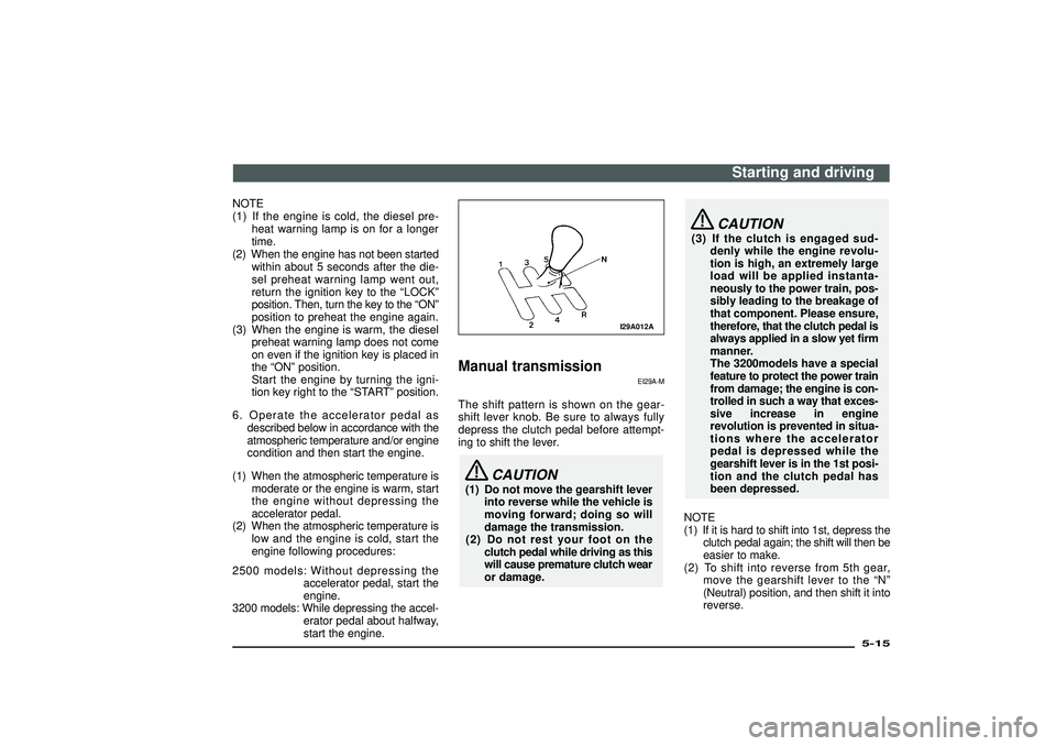
Manual transmission
EI29A-M
The shift pattern is shown on the gear-
shift lever knob. Be sure to always fully
depress the clutch pedal before attempt-
ing to shift the lever.
CAUTION
(1) Do not move the gearshift lever
into reverse while the vehicle is
moving forward; doing so will
damage the transmission.
(2) Do not rest your foot on the
clutch pedal while driving as this
will cause premature clutch wear
or damage.
CAUTION
(3) If the clutch is engaged sud-
denly while the engine revolu-
tion is high, an extremely large
load will be applied instanta-
neously to the power train, pos-
sibly leading to the breakage of
that component. Please ensure,
therefore, that the clutch pedal is
always applied in a slow yet firm
manner.
The 3200models have a special
feature to protect the power train
from damage; the engine is con-
trolled in such a way that exces-
sive increase in engine
revolution is prevented in situa-
tions where the accelerator
pedal is depressed while the
gearshift lever is in the 1st posi-
tion and the clutch pedal has
been depressed.
NOTE
(1) If it is hard to shift into 1st, depress the
clutch pedal again; the shift will then be
easier to make.
(2) To shift into reverse from 5th gear,
move the gearshift lever to the“N”
(Neutral) position, and then shift it into
reverse.
Starting and driving
5-15
Div:
Out put date:
Page 181 of 392
Waiting
EI04G-Ee
For short waiting periods, such as at traf-
fic signal, the vehicle can be left in gear and
held stationary with the service brake.
For longer waiting periods with the engine
running, the selector lever should be placed
in the“N”(NEUTRAL) position.
CAUTION
(1) Never hold the vehicle station-
ary while in gear on a hill with
the accelerator, always apply the
parking brake and/or service
brake.
(2) Unexpected acceleration may
occur if the selector lever is in a
position other than“P”(PARK)
or“N”(NEUTRAL).
Prior to moving off after having
stopped the vehicle, make sure
that the selector lever is in“D”
(DRIVE) or“Sports mode”posi-
tion.
Parking
EI04H-Be
To park the vehicle, first bring it to a com-
plete stop, fully engage the parking brake,
and then move the selector lever to the“P”
(PARK) position.
If you are going to leave the vehicle unat-
tended, always switch off the engine and
remove the ignition key.
NOTE
On a slope, be sure to apply the parking
brake before moving the selector lever to
the“P”(PARK) position. If you move the
selector lever to the“P”(PARK) position
without first applying the parking brake, a
stronger than normal resistance force may
be encountered. In this situation, move the
selector lever strongly when you next wish
to drive.
Starting and driving
5-23
Div:
Out put date:
Page 201 of 392
I07A049A
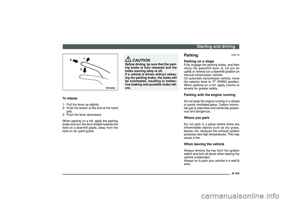
To release
1- Pull the lever up slightly.
2- Push the button at the end of the hand
grip.
3- Push the lever downward.
When parking on a hill, apply the parking
brake and turn the front wheels towards the
kerb on a downhill grade, away from the
kerb on an uphill grade.
CAUTION
Before driving, be sure that the park-
ing brake is fully released and the
brake warning lamp is off.
If a vehicle is driven without releas-
ing the parking brake, the brake will
be overheated, resulting in ineffec-
tive braking and possible brake fail-
ure.
Parking
EI22A-He
Parking on a slopeFully engage the parking brake, and then
move the gearshift lever to 1st (on an
uphill) or reverse (on a downhill) position on
manual transmission vehicle.
On automatic transmission vehicle, move
the selector lever to“P”(PARK) position.
When parking on a hill, apply chocks to
wheels for greater safety.Parking with the engine runningDo not keep the engine running in a closed
or poorly ventilated place. Carbon monox-
ide gas is odourless and extremely poison-
ous and dangerous.Where you parkDo not park in a place where there are
inflammable objects such as dry grass,
leaves, etc. because the exhaust system
produces very high temperatures. This may
cause a fire.When leaving the vehicleAlways remove the key from the ignition
switch and lock all doors when leaving the
vehicle unattended.
Always try to park your vehicle in a well lit
area.
Starting and driving
5-43
Div:
Out put date:
Page 283 of 392
G14A100A
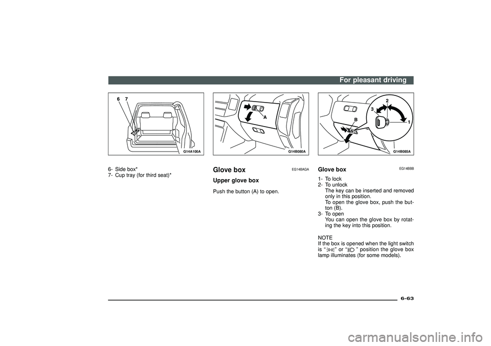
6- Side box*
7- Cup tray (for third seat)*
G14B080A
Glove box
EG14BAGA
Upper glove boxPush the button (A) to open.
G14B085A
Glove box
EG14BBB
1- To lock
2- To unlock
The key can be inserted and removed
only in this position.
To open the glove box, push the but-
ton (B).
3- To open
You can open the glove box by rotat-
ing the key into this position.
NOTE
If the box is opened when the light switch
is“
”or“
”position the glove box
lamp illuminates (for some models).
For pleasant driving
6-63
Div:
Out put date:
Page 306 of 392
N21D090A
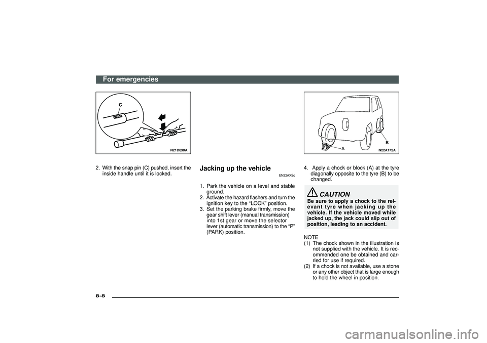
2. With the snap pin (C) pushed, insert theinside handle until it is locked.
Jacking up the vehicle
EN22AXSc
1. Park the vehicle on a level and stableground.
2. Activate the hazard flashers and turn the ignition key to the “LOCK” position.
3 . Se tth e parkin gbrak efirml y, mov ethe
gea rshif tleve r(manua ltransmission )
into 1st gear or move the selector
leve r(automati ctransmission )to the “P ”
(PARK) position.
N22A172A
4. Apply a chock or block (A) at the tyre diagonally opposite to the tyre (B) to be
changed.
CAUTION
Be sure to apply a chock to the rel-
evant tyre when jacking up the
vehicle. If the vehicle moved while
jacked up, the jack could slip out of
position, leading to an accident.
NOTE
(1) The chock shown in the illustration is not supplied with the vehicle. It is rec-
ommended one be obtained and car-
ried for use if required.
(2) If a chock is not available, use a stone or any other object that is large enough
to hold the wheel in position.
For emergencies
8-8Div:
Out put date:
Page 309 of 392
NOTE
Take care when lowering the vehicle, as
sudden closure of the jack release valve
can cause damage to the jack.
3. Remove the jack.
NOTE
(1) Occasionally, when the vehicle is
raised, the grooved portion of the ram
will not disengage. When this hap-
pens, rock the vehicle to lower the ram.
(2) When the jack is difficult to remove by
hand, insert the jack handle into the
holder and hook the jack handle notch
onto the holder notch and secure it
there. Then pull the jack handle and
remove the jack.
4. Press the piston down all the way, and
turn the release valve clockwise as far
as possible.
5. Store the jack and jack handle.
WARNING
(1) Raise the vehicle so the tyre just
clears the ground. It is danger-
ous to raise the vehicle any
higher.
(2) Never get under the vehicle while
using the jack. Avoid jarring the
raised vehicle or leaving it sup-
ported on the jack for any longer
than required. Both are very
dangerous.
(3) Do not start or run the engine
while the vehicle is on the jack.
The vehicle might start moving
causing the vehicle to fall down
from the jack.
(4) Do not turn the jacked up
wheels. The tyres remaining on
the ground may turn, causing
the vehicle body to fall down
from the jack.
(5) No one should stay in the vehicle
while the jack is used.
CAUTION
Use only the jack included with the
vehicle, and use it only for chang-
ing wheels.
N03A358A
Spare wheel
EN23A-N
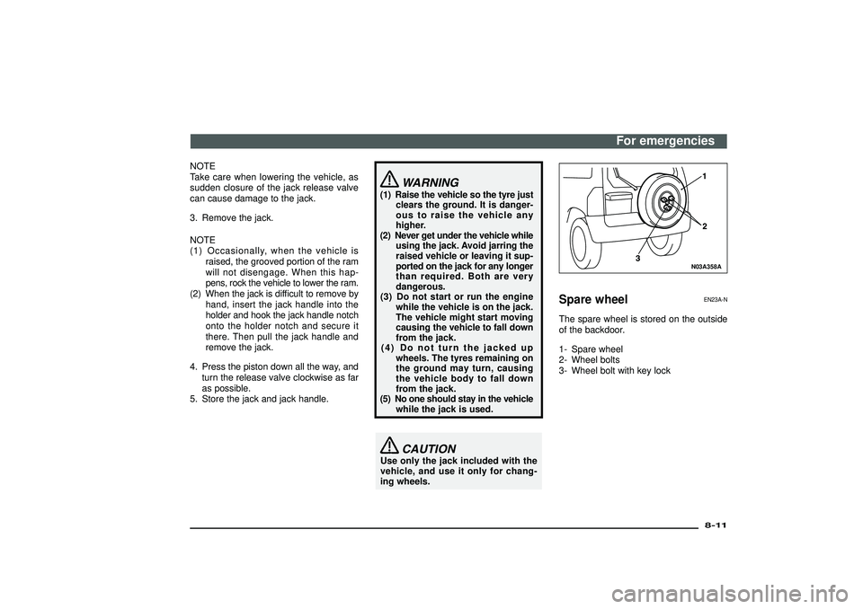
The spare wheel is stored on the outside
of the backdoor.
1- Spare wheel
2- Wheel bolts
3- Wheel bolt with key lock
For emergencies
8-11
Div:
Out put date:
Page 310 of 392
CAUTION
(1) Grasp the spare wheel firmly
when removing or attaching it.
(2) When removing the spare wheel,
put on gloves. Removing the
spare wheel with your hands
may cause injury to the fin-
gers.
(3) Check the air pressure of the
spare wheel frequently and
make sure it is ready for emer-
gency use at any time.
Driving with an insufficient tyre
pressure can lead to an acci-
dent. If you have no choice but
to drive with an insufficient tyre
pressure, keep your speed down
and inflate the tyre to the cor-
rect pressure as soon as pos-
sible. (Refer to“Tyre inflation
pressure”on page 9-14.)
Maintaining the spare wheel at
the highest specified air pres-
sure will ensure that it can
always be used under any con-
ditions (city/high-speed driv-
ing, varying load weight, etc.)
N03A082A
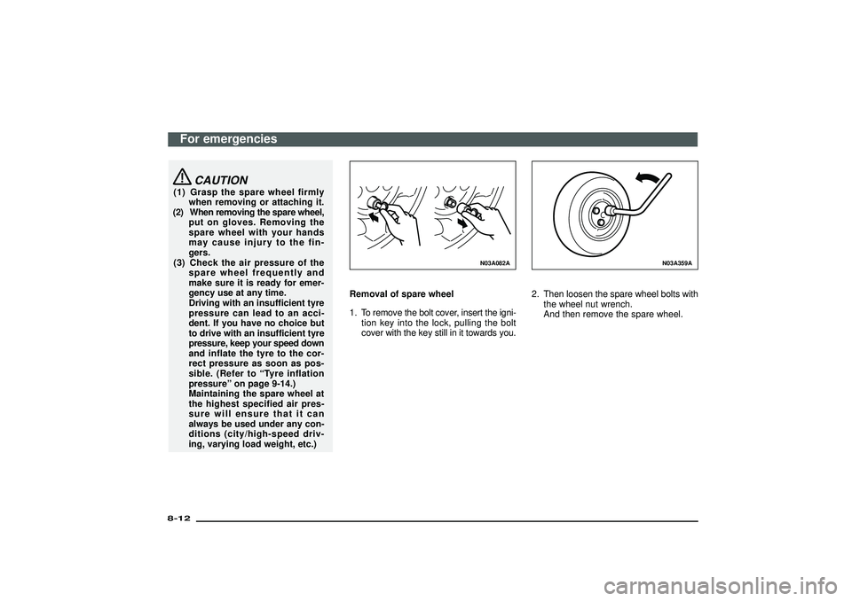
Removal of spare wheel
1. To remove the bolt cover, insert the igni-
tion key into the lock, pulling the bolt
cover with the key still in it towards you.
N03A359A
2. Then loosen the spare wheel bolts with
the wheel nut wrench.
And then remove the spare wheel.
For emergencies
8-12Div:
Out put date:
Page 311 of 392
N03A362A
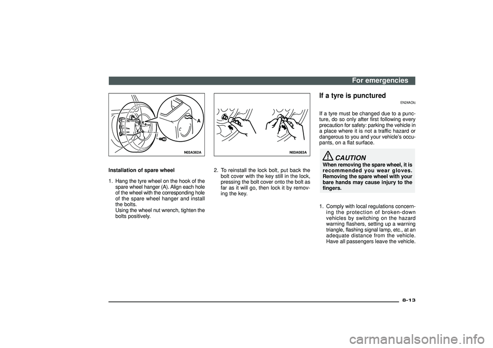
Installation of spare wheel
1. Hang the tyre wheel on the hook of the
spare wheel hanger (A). Align each hole
of the wheel with the corresponding hole
of the spare wheel hanger and install
the bolts.
Using the wheel nut wrench, tighten the
bolts positively.
N03A083A
2. To reinstall the lock bolt, put back the
bolt cover with the key still in the lock,
pressing the bolt cover onto the bolt as
far as it will go, then lock it by remov-
ing the key.
If a tyre is punctured
EN24AOIc
If a tyre must be changed due to a punc-
ture, do so only after first following every
precaution for safety: parking the vehicle in
a place where it is not a traffic hazard or
dangerous to you and your vehicle’s occu-
pants, on a flat surface.
CAUTION
When removing the spare wheel, it is
recommended you wear gloves.
Removing the spare wheel with your
bare hands may cause injury to the
fingers.
1. Comply with local regulations concern-
ing the protection of broken-down
vehicles by switching on the hazard
warning flashers, setting up a warning
triangle, flashing signal lamp, etc., at an
adequate distance from the vehicle.
Have all passengers leave the vehicle.
For emergencies
8-13
Div:
Out put date: