clock MITSUBISHI SHOGUN 2017 (in English) User Guide
[x] Cancel search | Manufacturer: MITSUBISHI, Model Year: 2017, Model line: SHOGUN, Model: MITSUBISHI SHOGUN 2017Pages: 394, PDF Size: 19 MB
Page 243 of 394
NOTElIf the text information for the service name
and ensemble name cannot be obtained, then
nothing is displayed.
During CD-DA playback
This switches in the order “Disc title”,
“Track title”, and “Operating status”.
NOTEl If there is no text information to display,
then “NO TITLE” is displayed.
During MP3/WMA/AAC Play-
back
This switches in the order “Folder title”,
“File title”, and “Operating status”.
NOTEl If there is no text information to display,
then “NO TITLE” is displayed.
Display the ID3tag
Hold down the DISP key.
This switches the ID3tag display.
[DISP] Each time the key is pressed, this
switches in the order “Album name”, “Track name”, “Artist name”, “Genre name”*, and “Operating status”.*:Displayed when playing back audio
files on a USB device (vehicles with a
Bluetooth ®
2.0 interface).NOTEl During display of the ID3tag, hold down the
DISP key to switch to the folder title dis- play.
l The genre name display may not be possible.During iPod Playback
E00738900015
This switches in the order “Albums”, “Track
name”, “Artist name”, “Genre name”*, and
“Operating status”.
NOTEl If there is no text information to display,
then “NO TITLE” is displayed.
l Displayed genre name in equipment by type
(vehicles with a Bluetooth ®
2.0 interface).
l The genre name display may not be possible.During Bluetooth ®
2.0 Audio
Playback*
E00739000013
Operating details are the same as in “During
iPod Playback” on page 7-41.
Audio Quality and Volume
Balance Adjustment E00738200021
Change audio quality settings.
Adjust Audio Quality and Vol-ume Balance
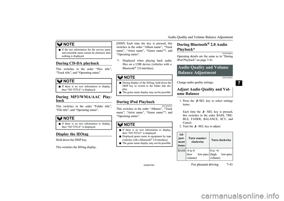
1. Press the /SEL key to select settings
items.
Each time the
/SEL key is pressed,
this switches in the order BASS, TRE-
BLE, FADER, BALANCE, SCV, and
Cancel.
2. Turn the
/SEL key to adjust.
Ad-
just-
ment
items
Turn counter- clockwiseTurn clockwise
BASS-6 to 0
(low low-pass
volume)0 to +6
(high low-pass
volume)
Audio Quality and Volume Balance Adjustment
7-41OVWX17E1For pleasant driving7
Page 244 of 394

Ad-
just-
ment
items
Turn counter- clockwiseTurn clockwise
TRE-
BLE-6 to 0
(Low high-pass
volume)0 to +6
(High high-pass
volume)FAD-
ERCENTER to REAR 11
(emphasise
REAR)FRONT 11 to
CENTER
(emphasise
FRONT)BAL-
ANC
ELEFT 11 to CENTER
(emphasise
LEFT)CENTER to
RIGHT 11
(emphasise
RIGHT)SCVOFF, LOW
(Low vehicle
compensated vol- ume effect)MID, HIGH
(High vehicle
compensated vol-
ume effect)System Settings
E00738301250
Change system settings such as product time.1. Press the MENU key.
2. Press the /SEL key to select settings
items.
Each time the
/SEL key is pressed,
this switches in the order DAB setting* 1
,
Gracenote DB* 2
, AF, REG, TP-S, PI-S,
PTY language settings, PHONE settings,
CT, Adjust time, and Cancel.
3. Turn the
/SEL key to set.
4. Press the
/SEL key to determine.
This completes settings, and displays the
next settings item.
* 1
:Displayed when a DAB tuner is con-
nected.* 2
:Displayed when playing back audio
files (vehicles with a Bluetooth ®
2.0 in-
terface).
DAB Setting*
Change DAB settings
(“Set value” bold typeface indicates factory
default settings.)
Settings
nameSettings val- ueSettings con-tentDAB-DAB
Link settingsOFFIf low recep-
tion sensitivi-
ty, switch to
another serv-
ice.ONIf low recep-
tion sensitivi-
ty, switch to
another serv-
ice.DAB Band settingsBAND IIISet used
broadcast
band to 174
to 239 MHz.L-BANDSet used
broadcast
band to 1452
to 1490 MHz.BOTHSet used
broadcast
band to Band
III and L-
Band.
System Settings
7-42OVWX17E1For pleasant driving7
Page 290 of 394

Luggage hooksE00715700306
There are hooks on the floor and the side of the luggage compartment. Use the hooks on
the floor for securing the luggage.
3-door models5-door models
CAUTIONl Do not pile up the luggage beyond the seat-
back height.
Secure the luggage firmly.
Otherwise, serious accidents could result due
to hindered rearward view or flying objects
during sudden braking.Coat hooks
E00725600366
There are two hooks on the rear/second assistgrips for use in hanging clothes.
WARNINGl Do not put a hanger or any heavy or poin-
ted object on the coat hook. If the curtain
airbag was activated, any such item could
be propelled away with great force and could prevent the curtain airbag from in-
flating correctly. Hang clothes directly on the coat hook (without using a hanger).
Make sure there are no heavy or sharp objects in the pockets of clothes that you
hang on the coat hook.Installation position for
warning triangle E00718400102
There are securing bands (A) for the warningtriangle on the backdoor.
To remove or install the warning triangle, turn the lock knobs (B) anticlockwise, then
remove the backdoor lid (C).
Luggage hooks
7-88OVWX17E1For pleasant driving7
Page 303 of 394

3.Remove the bolts (B) by turning them
anticlockwise with the wheel nut
wrench.
4. Close the backdoor.
5. Open the spare wheel garnish (C).
CAUTIONl Do not open the backdoor with the spare
wheel garnish open. The spare wheel garnish
could swing out to the right of the vehicle, resulting in an accident.
6. Loosen the spare wheel bolts with the
wheel nut wrench (D), then remove the spare wheel.
NOTEl Put the spare wheel under the vehicle body
near the flat tyre. This makes it safer if the jack slips out of position.To change a tyre
E00803202543
1. Loosen the wheel nuts a quarter turn
with the wheel nut wrench. Do not re- move the wheel nuts yet.
How to change a tyre
8-11OVWX17E1For emergencies8
Page 304 of 394

2.Using the jack handle, turn the release
valve (A) clockwise until it stops.
3. Insert the jack handle in the bracket of
the jack and hook the notch (B) on the
jack handle end to the claw (C) of the bracket.
4. Place the jack under one of the jacking
points shown in the illustration. Use the
jacking point closest to the tyre you wish
to change.
D- Front jacking point
E- Rear jacking point
WARNINGl Set the jack only at the positions shown
here. If the jack is set at a wrong position, it could dent your vehicle or the jack
might fall over and cause personal injury.
l Do not use the jack on a tilted or soft sur-
face. Otherwise, the jack might slip and cause personal injury. Always use the jack on a flat, hard surface. Before setting
the jack, make sure there are no sand or pebbles under the jack base.
5. Move the jack handle up and down to
raise the ram until just before the jack contacts the jacking point of the vehicle.
Ensure that the jack will properly con- tact the vehicle jacking point.
NOTEl This jack is a 3 stage expansion type.
6.
Raise the vehicle until the tyre is slightly
off the ground.
WARNINGl Stop jacking up the vehicle as soon as the
tyre is raised off the ground. It is danger-
ous to raise the vehicle any higher.
l Do not get under your vehicle while using
the jack.
How to change a tyre
8-12OVWX17E1For emergencies8
Page 305 of 394
WARNINGlDo not bump the raised vehicle or leave it
sitting on the jack for a long time. Bothare very dangerous.
l Do not use a jack except the one that
came with your vehicle.
l The jack should not be used for any pur-
pose other than to change a tyre.
l No one should be in your vehicle when us-
ing the jack.
l Do not start or run the engine while your
vehicle is on the jack.
l Do not turn the raised wheel. The tyres
still on the ground could turn and make your vehicle fall off the jack.
7. Remove the wheel nuts with the wheel
nut wrench, then take the wheel off.
CAUTIONl Handle the wheel carefully when changing
the tyre, to avoid scratching the wheel sur- face.
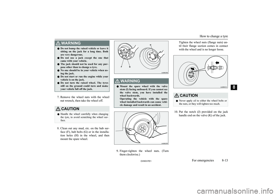
8. Clean out any mud, etc. on the hub sur-
face (F), hub bolts (G) or in the installa- tion holes (H) in the wheel, and then
mount the spare wheel.
WARNINGl Mount the spare wheel with the valve
stem (I) facing outboard. If you cannot see
the valve stem, you have installed the wheel backwards.
Operating the vehicle with the spare
wheel installed backwards can cause vehi-
cle damage and result in an accident.
9. Finger-tighten the wheel nuts. (Turn
them clockwise.)
Tighten the wheel nuts (flange nuts) un-
til their flange section comes in contact
with the wheel and is no longer loose.CAUTIONl Never apply oil to either the wheel bolts or
the nuts, or they will tighten too much.
10. Put the notch (J) provided on the jack
handle end on the valve (K) of the jack.
How to change a tyre
8-13OVWX17E1For emergencies8
Page 306 of 394

Using the jack handle, turn the releasevalve anticlockwise slowly to lower thevehicle until the tyre touches the ground.WARNINGl Be sure to open the release valve slowly. If
it is opened quickly, the vehicle will drop
abruptly and the jack may come out of
position, causing a serious accident.
11. Tighten the nuts crisscross in 2 or 3
steps until each nut has been tightened
securely.
Tightening torque
105 to 125 N•m
(Achieved by applying a force of 390
to 460 N at the end of the wheel nut wrench supplied with the vehicle.)CAUTIONl Never use your foot or a pipe extension for
extra force in the wheel nut wrench. If you
do so, you will tighten the nut too much.
12. Lower the jack all the way and remove
it.
CAUTIONl If the release valve is loosened too much (2
or more turns) in the anticlockwise direction, the jack’s oil will leak and the jack cannotbe used.CAUTIONl Close the release valve slowly when lower-
ing the vehicle, or the valve may be dam-
aged.NOTEl Occasionally when the vehicle is jacked up,
the grooved portion of the designated pointwill not come off. When this happens, rock
the vehicle to lower the ram.
l If the jack is difficult to remove by hand, in-
sert the jack handle (L) into the bracket (M).Then using the handle, remove the jack.
13. Press the piston down all the way, and
turn the release valve clockwise as far as possible.
How to change a tyre
8-14OVWX17E1For emergencies8
Page 343 of 394
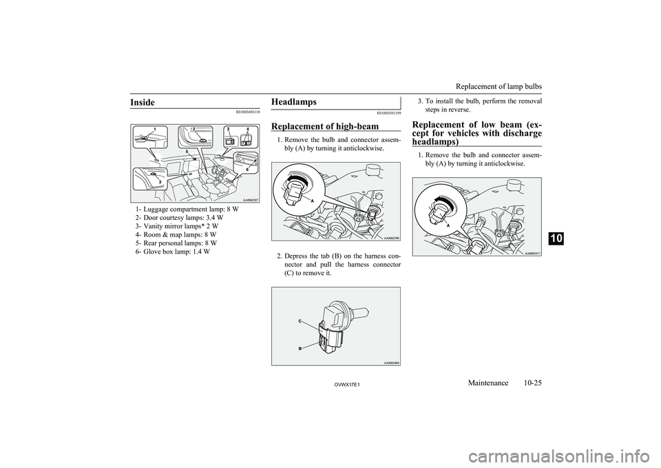
Inside
E01003403118
1- Luggage compartment lamp: 8 W
2- Door courtesy lamps: 3.4 W
3- Vanity mirror lamps* 2 W
4- Room & map lamps: 8 W
5- Rear personal lamps: 8 W
6- Glove box lamp: 1.4 W
Headlamps
E01003501199
Replacement of high-beam
1. Remove the bulb and connector assem-
bly (A) by turning it anticlockwise.
2. Depress the tab (B) on the harness con-
nector and pull the harness connector
(C) to remove it.
3. To install the bulb, perform the removal
steps in reverse.
Replacement of low beam (ex-
cept for vehicles with discharge
headlamps)
1. Remove the bulb and connector assem-
bly (A) by turning it anticlockwise.
Replacement of lamp bulbs
10-25OVWX17E1Maintenance10
Page 344 of 394
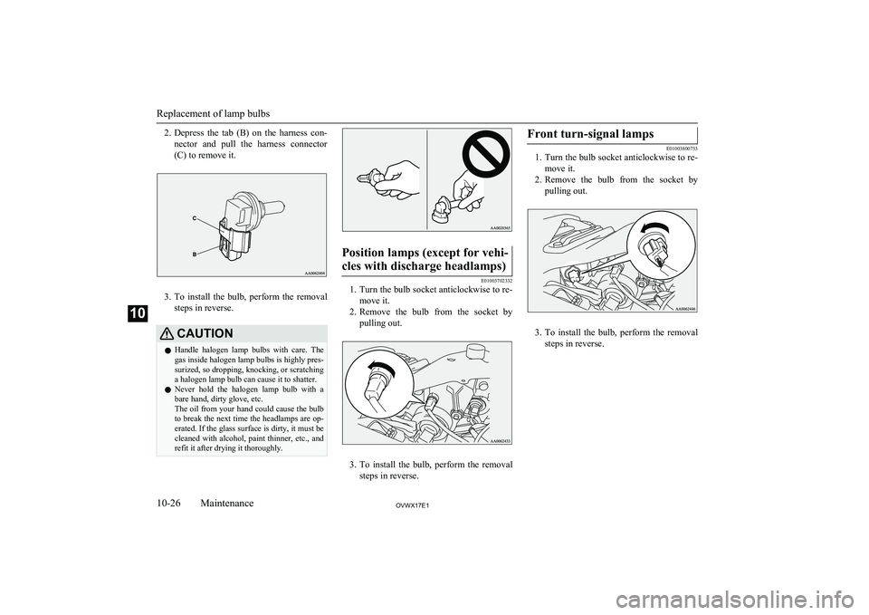
2.Depress the tab (B) on the harness con-
nector and pull the harness connector
(C) to remove it.
3. To install the bulb, perform the removal
steps in reverse.
CAUTIONl Handle halogen lamp bulbs with care. The
gas inside halogen lamp bulbs is highly pres- surized, so dropping, knocking, or scratching
a halogen lamp bulb can cause it to shatter.
l Never hold the halogen lamp bulb with a
bare hand, dirty glove, etc.
The oil from your hand could cause the bulb to break the next time the headlamps are op-
erated. If the glass surface is dirty, it must be cleaned with alcohol, paint thinner, etc., andrefit it after drying it thoroughly.Position lamps (except for vehi-
cles with discharge headlamps)
E01003702332
1. Turn the bulb socket anticlockwise to re-
move it.
2. Remove the bulb from the socket by
pulling out.
3. To install the bulb, perform the removal
steps in reverse.
Front turn-signal lamps
E01003800733
1. Turn the bulb socket anticlockwise to re-
move it.
2. Remove the bulb from the socket by
pulling out.
3. To install the bulb, perform the removal
steps in reverse.
Replacement of lamp bulbs
10-26OVWX17E1Maintenance10
Page 345 of 394
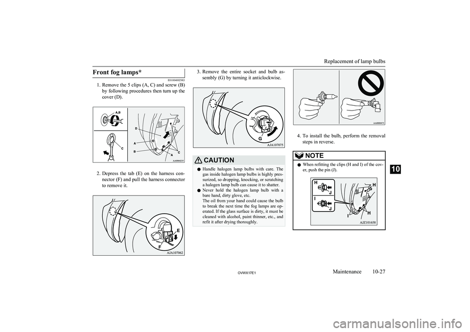
Front fog lamps*
E01004002983
1. Remove the 5 clips (A, C) and screw (B)
by following procedures then turn up the cover (D).
2. Depress the tab (E) on the harness con-
nector (F) and pull the harness connector
to remove it.
3. Remove the entire socket and bulb as-
sembly (G) by turning it anticlockwise.CAUTIONl Handle halogen lamp bulbs with care. The
gas inside halogen lamp bulbs is highly pres-
surized, so dropping, knocking, or scratching
a halogen lamp bulb can cause it to shatter.
l Never hold the halogen lamp bulb with a
bare hand, dirty glove, etc.
The oil from your hand could cause the bulb to break the next time the fog lamps are op- erated. If the glass surface is dirty, it must becleaned with alcohol, paint thinner, etc., and
refit it after drying thoroughly.
4. To install the bulb, perform the removal
steps in reverse.
NOTEl When refitting the clips (H and I) of the cov-
er, push the pin (J).
Replacement of lamp bulbs
10-27OVWX17E1Maintenance10