belt MITSUBISHI SPYDER 1990 Service Repair Manual
[x] Cancel search | Manufacturer: MITSUBISHI, Model Year: 1990, Model line: SPYDER, Model: MITSUBISHI SPYDER 1990Pages: 2103, PDF Size: 68.98 MB
Page 593 of 2103
![MITSUBISHI SPYDER 1990 Service Repair Manual ENGINE (TURBO)
AND
ENGINE> Troubleshooting
INSPECTION PROCEDURE 17
Probable causeI
[Comment]l Malfunction of the system
Malfunction of the system is suspected.
Are diagnostic troubl](/img/19/57345/w960_57345-592.png "MITSUBISHI SPYDER 1990 Service Repair Manual ENGINE (TURBO)
AND
ENGINE> Troubleshooting
INSPECTION PROCEDURE 17
Probable causeI
[Comment]l Malfunction of the system
Malfunction of the system is suspected.
Are diagnostic troubl")
ENGINE (TURBO)
AND
ENGINE> Troubleshooting
INSPECTION PROCEDURE 17
Probable causeI
[Comment]l Malfunction of the system
Malfunction of the system is suspected.
Are diagnostic trouble codes output
YESRefer to INSPECTION FOR DIAGNOSTICTROUBLE CODES.
Check theidle air control motor for operation sound Engine (Refer to Check the idle air control motor for operation soun d Engine>. (Refer to
SCAN TOOL Data list
14 Throttle position sensor (Refer to
OK
Check the idle control system malfunction (Refer t o INSPECTION PROCEDURE FOR DIAGNOSTIC TROUBLE CODE
Check the throttle position circuit malfunction (Refer to PROCEDURE FOR DIAGNOSTIC TROUBLE 20.)
NG,
SCAN TOOL Data list Check closed position switch system.
26 Closed throttle position switch (Refer to (Refer to INSPECTION PROCEDURE FOR DIAGNOSTICTROUBLE CODE .
. .
Clean the throttle valve area. (Refer to
INSPECTION PROCEDURE 18
Poor acceleration Probable cause I
[Comment]
Defective ignition system, abnormal air-fuel ratio, poor compression pressure, etc. are l Malfunction of the Ignition system Malfunction of air-fuel ratio control l Malfunction of the fuel supply system Poor acceleration
l C l o g g e d e x h a u s t s y s t e m
l Malfunction ‘of turbocharger system .
SCAN TOOL DTC
Are diagnostic trouble codes output
YESRefer to INSPECTION CHART FOR DIAGNOSTICTROUBLE CODES.
Check the injectors for opNG
(Refer to PROCEDURE FOR DIAGNOSTIC TROUBLE
OK
Check the ignition timing. Engine (Turbo)>
(Refer to GROUP A On-vehicle Service.)
Check the ignition timing. Engine>
Check that the crankshaft position sensor and timi ng belt cover are
installed
(Refer to GROUP On-vehicle Service.)
OK
Scan tool: Inspection when hesitation. stumble or poor acceleration occur. (Refer to INSPECTIONPROCEDURE 42.)I
OK
Check the fuel pressure. (Refer to
OK
Check the following items.
l Check the ignition coil, spark plugs, spark plug ca bles.
l Check supercharging pressure.
l Check intake charge pressure control system.
l Check rotating resistance of turbocharger turbine w heel. (Does the wheel rotate smoothly?)
l Check the compression pressure.
lCheck the fuel filter or fuel for clogging.
l Broken air intake hose
Clogged air cleaner
l Clogged exhaust system
Revision
Page 595 of 2103
![MITSUBISHI SPYDER 1990 Service Repair Manual ENGINE (TURBO)
AND ENGINE> Troubleshooting
INSPECTION PROCEDURE 22
Too high CO and HC concentration when idling
[Comment]Malfunction of the ratio
Abnormal air-fuel ratio is susp](/img/19/57345/w960_57345-594.png "MITSUBISHI SPYDER 1990 Service Repair Manual ENGINE (TURBO)
AND ENGINE> Troubleshooting
INSPECTION PROCEDURE 22
Too high CO and HC concentration when idling
[Comment]Malfunction of the ratio
Abnormal air-fuel ratio is susp")
ENGINE (TURBO)
AND ENGINE> Troubleshooting
INSPECTION PROCEDURE 22
Too high CO and HC concentration when idling
[Comment]Malfunction of the ratio
Abnormal air-fuel ratio is suspected.
SCAN TOOL Are diagnostic trouble codes output
N O
YES Refer to INSPECTION CHART FOR DIAGNOSTICTROUBLE CODES.
Check the ignition timing. Engine (Turbo)>NG
(Refer to GROUP On-vehicle Service.) Check that the crankshaft position sensor and belt installedCheck the ignition timing. Engine>(Refer to GROUP 11 On-vehicle Service.)
OK
NGSCAN TOOL Data list
21 Engine coolant temperature sensor. Check the engine coolant temperature malfunction. (Refer to
(Refer to INSPECTION PROCEDURE FOR DIAGNOSTIC
TROUBLE CODES
OK
SCAN TOOL Data listNG Check the intake air temperature (Refer to
13 Intake air temperature sensor (Refer to INSPECTION PROCEDURE FOR DIAGNOSTIC
OK TROUBLE CODE
SCAN TOOL Data list
25 Barometric pressure sensor (Refer to
OK
Check the pressure circuit malfunction. INSPECTION PROCEDURE FOR DIAGNOSTIC TROUBLE CODE
SCAN TOOL Data listNGCheck the oxygen sensor circuit malfunction (bank sensor 2). (Refer59 Heated oxygen sensor (rear) (Refer to to INSPECTION PROCEDURE FOR DIAGNOSTIC
l Transaxle gear TROUBLE CODE ranae l Driving with the throttle wide open
O K :
OK
SCAN TOOL Data list NG
Heated oxygen sensor (front) (Refer to OK: 1,000 when racing suddenly
OK
SCAN TOOL Data list11 Heated oxygen sensor (front) (Refer to O K : and
Check the oxygen sensor circuit malfunction (bank 1 sensor 1). INSPECTION PROCEDURE FOR DIAGNOSTICTROUBLE CODE
alternately when idling.
NG
Check the fuel pressure. (Refer to
Check the following items.
l Check the injectors for operation sound.
l Check the injectors for fuel leakage.
l Check the ignition coil, spark plugs, spark plug ca bles.
l Check the compression pressure.
l Check the positive crankcase ventilation system.
l Check the evaporative emission control system.
l Check the
system.I
Check trouble symptom.
Replace the three-way converter.
TSB Revision
Page 598 of 2103
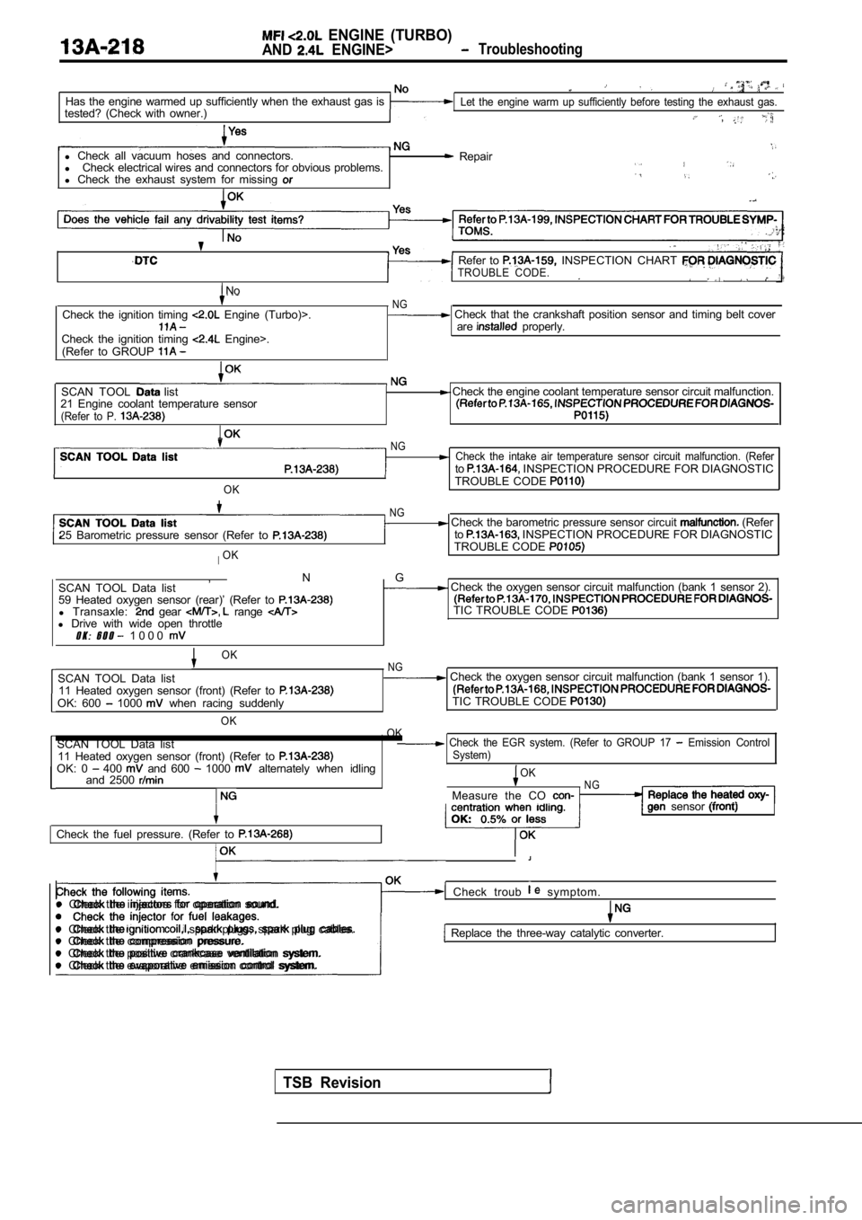
ENGINE (TURBO)
AND ENGINE> Troubleshooting
Has the engine warmed up sufficiently when the exhaust gas is
tested? (Check with owner.)Let the engine warm up sufficiently before testing the exhaust gas.
,
l Check all vacuum hoses and connectors.
l Check electrical wires and connectors for obvious p roblems.
l Check the exhaust system for missing Repair
No
Check the ignition timing Engine (Turbo)>.
Check the ignition timing Engine>.
(Refer to GROUP
Refer to INSPECTION CHART TROUBLE CODE.
NG Check that the crankshaft position sensor and timi ng belt cover
are properly.
SCAN TOOL list
21 Engine coolant temperature sensor
(Refer to P.
Check the engine coolant temperature sensor circui t malfunction.
OK
NGCheck the intake air temperature sensor circuit mal function. (Referto INSPECTION PROCEDURE FOR DIAGNOSTIC
TROUBLE CODE
25 Barometric pressure sensor (Refer to
IOK
NG Check the barometric pressure sensor circuit (Refer
to INSPECTION PROCEDURE FOR DIAGNOSTIC
TROUBLE CODE
, N G
SCAN TOOL Data list Check the oxygen sensor circuit malfunction (bank 1 sensor 2).
59 Heated oxygen sensor (rear)’ (Refer to
l Transaxle: gear range TIC TROUBLE CODE l Drive with wide open throttleO K : 6 0 0 1 0 0 0
TSB Revision
OKNGSCAN TOOL Data list Check the oxygen sensor circuit malfunction (bank 1 sensor 1).
11 Heated oxygen sensor (front) (Refer to
OK: 600 1000 when racing suddenly TIC TROUBLE CODE
OK
OK
SCAN TOOL Data list Check the EGR system. (Refer to GROUP 17 Emission Control11 Heated oxygen sensor (front) (Refer to System)OK: 0 400 and 600 1000 alternately when idling
and 2500 OKNGMeasure the CO
Check the fuel pressure. (Refer to
sensor
l Check the injector for fuel leakages.
Check troub symptom. l Check the injectors for operation sound.
l Check the
spark plugs, spark plug cables.l Check the compression pressure. Replace the three-way catalytic converter.
l Check the positive crankcase ventilation system.
l Check the evaporative emission control system.
Page 607 of 2103
![MITSUBISHI SPYDER 1990 Service Repair Manual ENGINE (TURBO)
AND
ENGINE> Troubleshooting
INSPECTION PROCEDURE 35
Idle air control motor (DC motor) Engine>P r o b a b l e c a u s e
[Comment]l Malfunction of idle air control mo](/img/19/57345/w960_57345-606.png "MITSUBISHI SPYDER 1990 Service Repair Manual ENGINE (TURBO)
AND
ENGINE> Troubleshooting
INSPECTION PROCEDURE 35
Idle air control motor (DC motor) Engine>P r o b a b l e c a u s e
[Comment]l Malfunction of idle air control mo")
ENGINE (TURBO)
AND
ENGINE> Troubleshooting
INSPECTION PROCEDURE 35
Idle air control motor (DC motor) Engine>P r o b a b l e c a u s e
[Comment]l Malfunction of idle air control motor
The ECM controls the intake air volume during idlin g by opening and closing the I m p r o p e r c o n n e c t o r open “circuit’ servo valve located in the bypass passage.
l Malfunction of the
at the idle air control motor connector Connect the connector. (Use test harness: Voltage between 5 and ground (Ignition switch: ON)
OK: 2 or more to 0 (momentarily) Voltage between 6 and ground (Ignition switch: ON)OK: 4 or more to 0 (momentarily)
OK
the idle air control motor.1
Check symptom.
Replace
INSPECTION PROCEDURE 36
Scan tool: Inspection when no initial combustion oc curs
SCAN TOOL Data listNGCheck the power and ignition 16 Voltage of ECM power source (Refer to (Refer to I PROCEDURE 27.)
(Whenoil filler cap is removed.)
SCAN TOOL DTC
Are the diagnostic trouble codes output
Check timing belt for breakage.
INSPECTION CHART FOR TROUBLE CODES.
(Refer to
SCAN TOOL list NG
22 Crankshaft position sensor OK: Cranking speed is displayed.
OK
Check the crankshaft position sensor circuit malfu nction. (Refer to INSPECTION PROCEDURE FOR DIAGNOSTIC
TROUBLE CODES
SCAN TOOL Actuator testCheck the fuel pump system Engine 07 Fuel pump (Refer to (Refer to INSPECTION PROCEDURE 28.)
OKCheck the fuel pump system (Refer to INSPECTION PROCEDURE 29) .
SCAN TOOL list21 Check the engine coolant temperature circuit (Refer to INSPECTION PROCEDURE FOR DIAGNOSTICTROUBLE CODES
TSB Revision
Page 636 of 2103
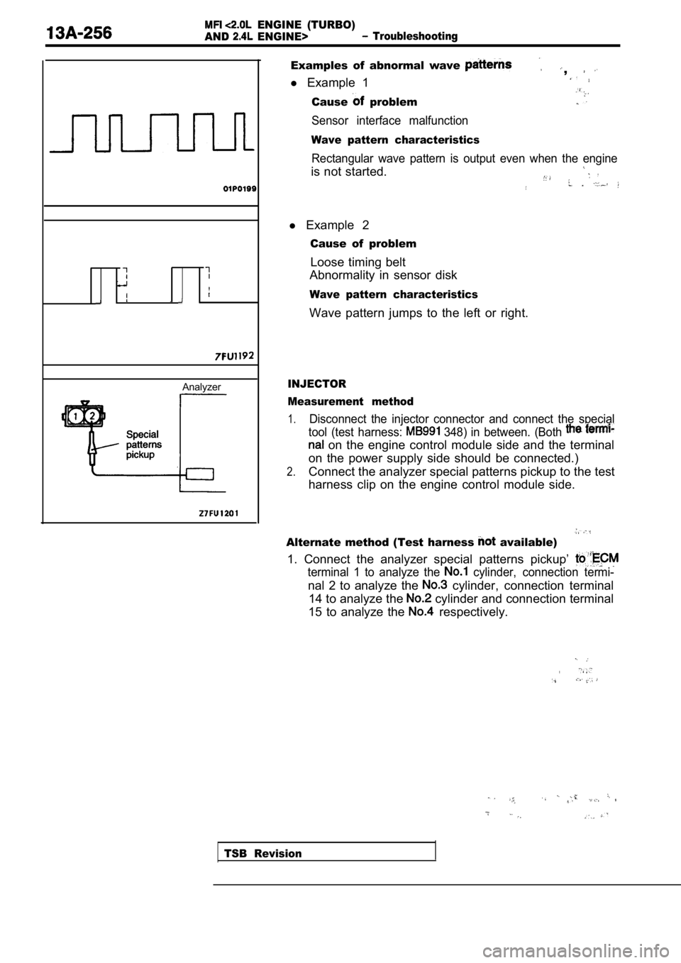
ENGINE (TURBO)
AND
ENGINE> Troubleshooting
Analyzer
Examples of abnormal wave ,
l Example 1
Cause problem
Sensor interface malfunction
Wave pattern characteristics
Rectangular wave pattern is output even when the en gine
is not started.
l Example 2
Cause of problem
Loose timing belt
Abnormality in sensor disk
Wave pattern characteristics
Wave pattern jumps to the left or right.
INJECTOR
Measurement method
1.Disconnect the injector connector and connect the s pecial
tool (test harness:
348) in between. (Both
on the engine control module side and the terminal
on the power supply side should be connected.)
2.Connect the analyzer special patterns pickup to the test
harness clip on the engine control module side.
Alternate method (Test harness available)
1. Connect the analyzer special patterns pickup’
terminal 1 to analyze the cylinder, connection termi-
nal 2 to analyze the cylinder, connection terminal
14 to analyze the
cylinder and connection terminal
15 to analyze the
respectively.
TSB Revision
Page 694 of 2103
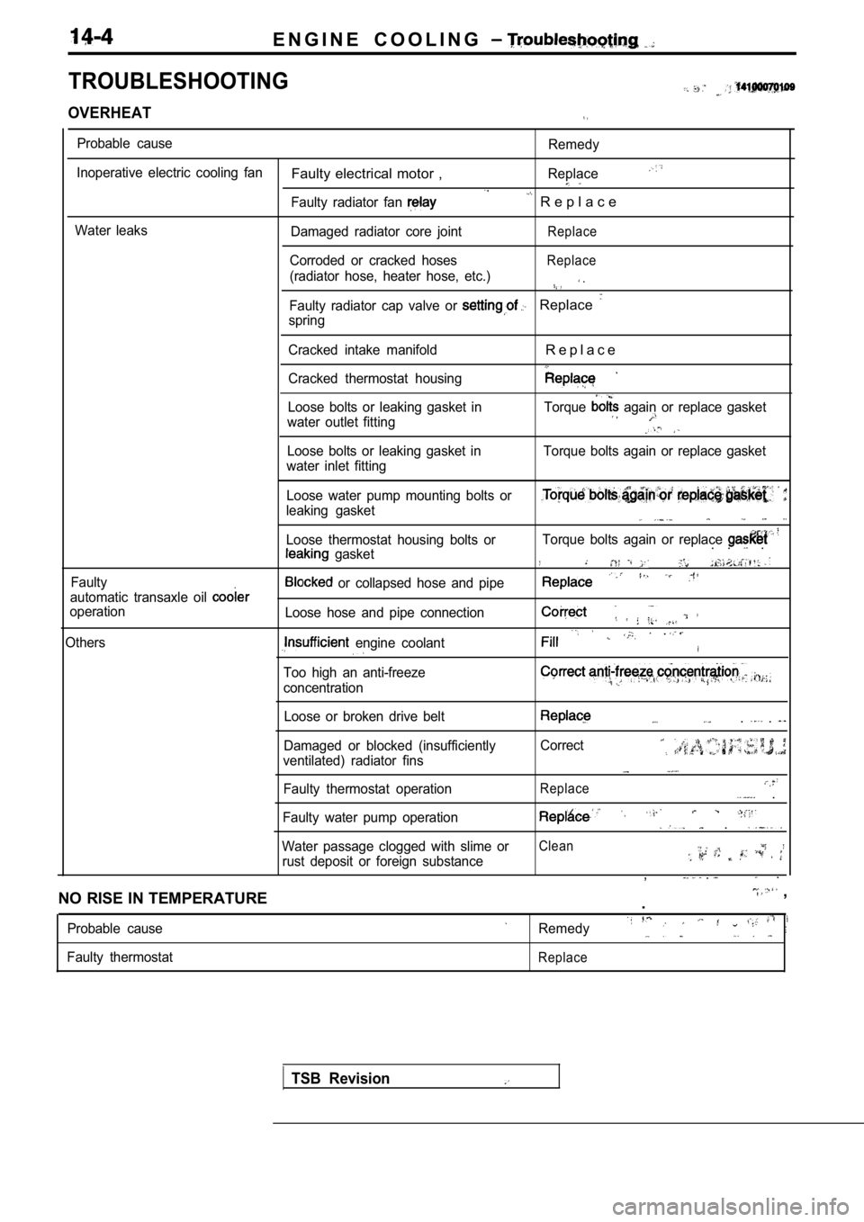
E N G I N E C O O L I N G
TROUBLESHOOTING
OVERHEAT
Probable cause
Inoperative electric cooling fan
Water leaks
Faulty electrical motor ,
Faulty radiator fan
Damaged radiator core joint
Corroded or cracked hoses
(radiator hose, heater hose, etc.)
Remedy
Replace
R e p l a c e
Replace
Replace
.
Faulty radiator cap valve or Replace
spring
Cracked intake manifold
Cracked thermostat housing
R e p l a c e
Loose bolts or leaking gasket in
water outlet fitting Torque again or replace gasket
Loose bolts or leaking gasket in
water inlet fitting Torque bolts again or replace gasket
Faulty Loose water pump mounting bolts or
leaking gasket
Loose thermostat housing bolts or
gasket
automatic transaxle oil
operation
Others
or collapsed hose and pipe
Loose hose and pipe connection
engine coolant
Too high an anti-freeze
concentration
Torque bolts again or replace . . .
.
Loose or broken drive belt
Damaged or blocked (insufficiently
ventilated) radiator fins
Faulty thermostat operation. .
Correct
Replace .
Faulty water pump operation .
Water passage clogged with slime orClean
rust deposit or foreign substance, . .
NO RISE IN TEMPERATURE
,
.
Probable cause
Faulty thermostatRemedy
Replace
TSB Revision
Page 706 of 2103
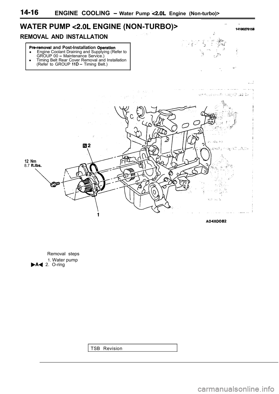
ENGINE COOLING Water Pump Engine (Non-turbo)>
WATER PUMP
ENGINE (NON-TURBO)>
REMOVAL AND INSTALLATION
and Post-Installation l Engine Coolant Draining and Supplying (Refer to
GROUP 00 Maintenance Service.)
l Timing Belt Rear Cover Removal and Installation
(Refer to GROUP
Timing Belt.)
.
12 Nm8.7
Removal steps
1. Water pump
2. O-ring
TSB Revision
Page 708 of 2103
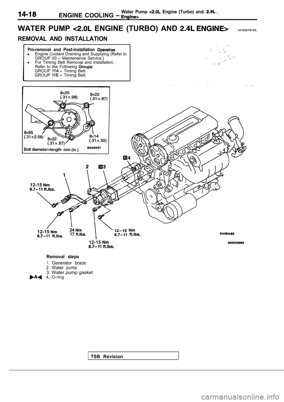
ENGINE COOLING Water Pump Engine (Turbo) and.
WATER PUMP ENGINE (TURBO) AND 1 4 1 0 0 2 7 0 1 5 5 ,
REMOVAL AND INSTALLATION
Pm-removal and Post-installation lEngine Coolant Draining and Supplying (Refer to
GROUP 00 Maintenance Service.)lFor Timinig Belt Removal and Installation,
Refer to the Following
GROUP Timing Belt.
GROUP Timing Belt.
,
12-15
TSB Revision
12-15
2417
12-15
Removal steps
1.Generator brace2.Waterpump
3. Water pump gasket4.O-ring
Page 1793 of 2103
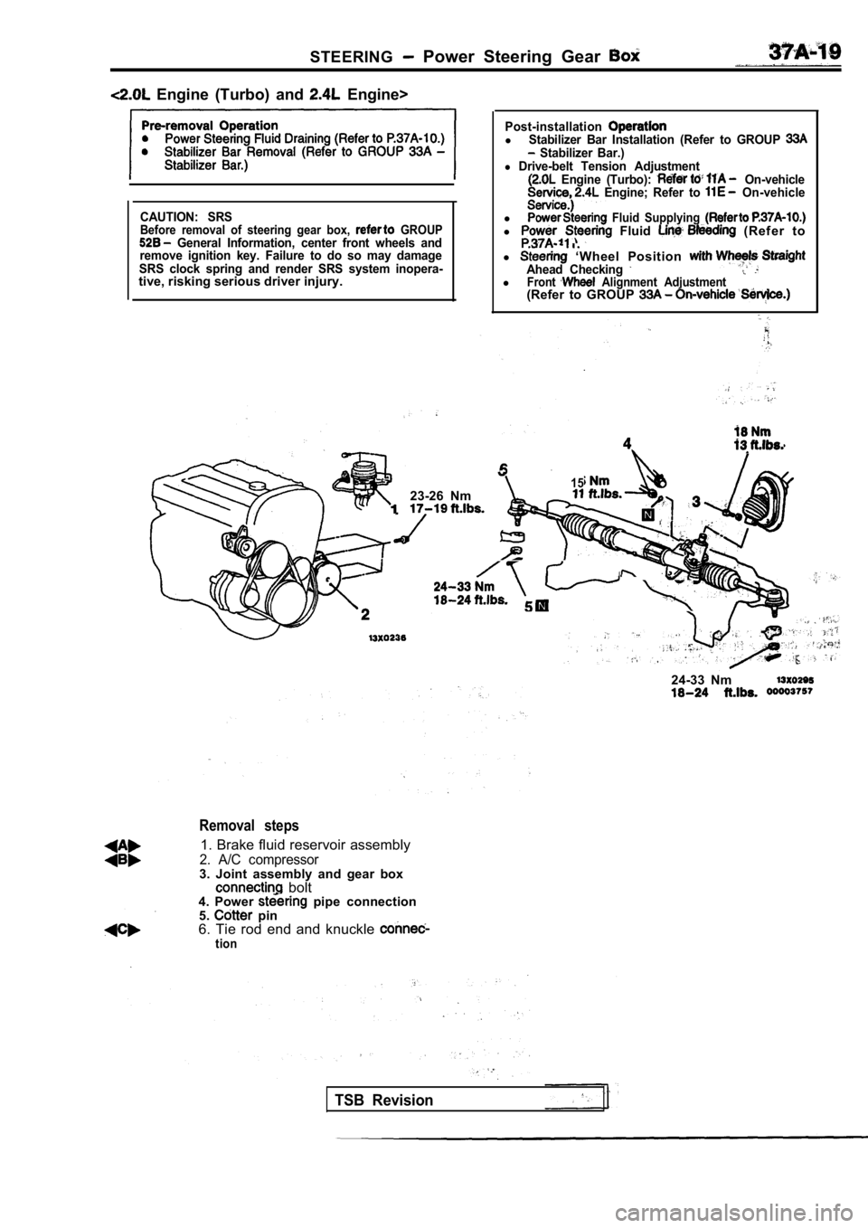
STEERING Power Steering Gear
Engine (Turbo) and Engine>
CAUTION: SRSBefore removal of steering gear box, GROUP General Information, center front wheels and
remove ignition key. Failure to do so may damage
SRS clock spring and render SRS system inopera-
tive, risking serious driver injury.
Post-installationlStabilizer Bar Installation (Refer to GROUP Stabilizer Bar.)l Drive-belt Tension Adjustment Engine (Turbo): On-vehicle Engine; Refer to On-vehicle
l Fluid Supplying l Fluid (Refer to
.
l ‘Wheel Position Ahead Checking lFront Alignment Adjustment(Refer to GROUP
1523-26 Nm
24-33 Nm
Removal steps
1. Brake fluid reservoir assembly
2. A/C compressor3. Joint assembly and gear box bolt 24-33 Nm4. Power pipe connection
5. pin
6. Tie rod end and knuckle
tion
TSB Revision
Page 1806 of 2103
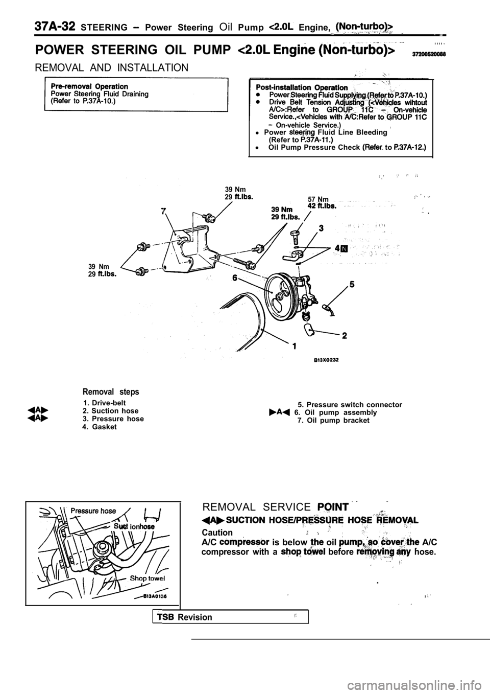
STEERING Power Steering OilPump Engine,
POWER STEERING OIL PUMP
. . . .
REMOVAL AND INSTALLATION
On-vehicle Service.)l Power Fluid Line Bleeding (Refer to l
Oil Pump Pressure Check to
39 Nm
29
57 Nm
.
39 Nm29
Removal steps
1. Drive-belt
2. Suction hose
3. Pressure hose
4. Gasket
uc ion ose
5. Pressure switch connector 6. Oil pump assembly 7. Oil pump bracket
REMOVAL SERVICE
Caution
A/C is below oil A/C
compressor with a before hose.
.
,
Revision