belt MITSUBISHI SPYDER 1990 Service Repair Manual
[x] Cancel search | Manufacturer: MITSUBISHI, Model Year: 1990, Model line: SPYDER, Model: MITSUBISHI SPYDER 1990Pages: 2103, PDF Size: 68.98 MB
Page 1887 of 2103
Door
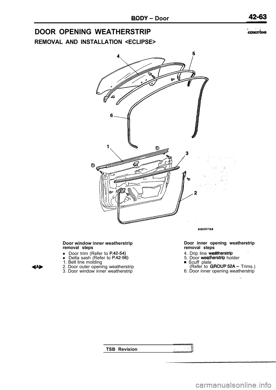
DOOR OPENING WEATHERSTRIP
REMOVAL AND INSTALLATION
Door window inner weatherstripremoval steps
l Door trim (Refer to l Delta sash (Refer to 1. Belt line molding
2. Door outer opening weatherstrip
3. Door window inner weatherstrip
Door inner opening weatherstrip
removal steps
4. Drip line 5. Door holder Scuff plate (Refer to Trims.)
6. Door inner opening weatherstrip
TSB Revision
Page 1918 of 2103
BODY Electric Convertible Top
CONVERTIBLE TOP FIT ADJUSTMENT
(1) Remove the quarter trim, lower (Refer to GROUP
Trims.)
(2) Fully open orclose the top, then adjust the stopper
adjusting bolt so it contacts the flange as shown in the
illustration.
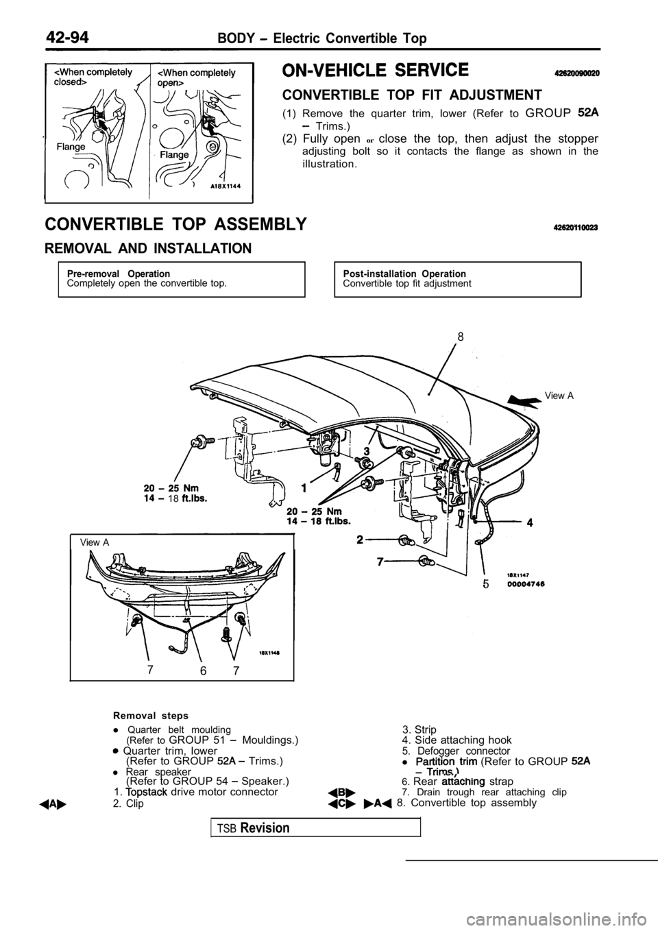
CONVERTIBLE TOP ASSEMBLY
REMOVAL AND INSTALLATION
Pre-removal OperationCompletely open the convertible top.Post-installation OperationConvertible top fit adjustment
8
View A
18
View A
76 7
5
Removal steps
3. Strip
l
Quarter belt moulding
(Refer to GROUP 51
Mouldings.) Quarter trim, lower
(Refer to GROUP Trims.)l Rear speaker(Refer to GROUP 54 Speaker.)
1. drive motor connector
2. Clip
4. Side attaching hook5. Defogger connectorl (Refer to GROUP
6. Rear strap
7. Drain trough rear attaching clip
8. Convertible top assembly
TSBRevision
Page 1937 of 2103
EXTERIOR Moldings
MOLDINGS
SEALANT AND ADHESIVE
ItemsSpecified sealant and adhesive
Side protector molding
Part No. 6382 or equivalent and
ATD Part No. 8608 Super Fast Urethane Primer or eq uivalent
MOLDINGS
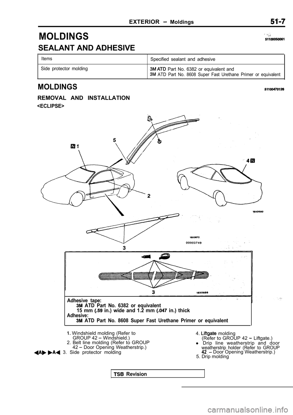
REMOVAL AND INSTALLATION
Adhesive tape:
ATD Part No. 6382 or equivalent
15 mm in.) wide and 1.2 mm in.) thick
Adhesive:
ATD Part No. 8608 Super Fast Urethane Primer or eq uivalent
Windshield molding (Refer to
GROUP 42 Windshield.)
2. Belt line molding (Refer to GROUP
42
Door Opening Weatherstrip.)
3. Side protector molding 4.
molding
(Refer to GROUP 42 Liftgate.)
l Drip line weatherstrip and door
weatherstrip holder (Refer to GROUP42 Door Opening Weatherstrip.)
5. Drip molding
Revision
Page 1938 of 2103
51-8
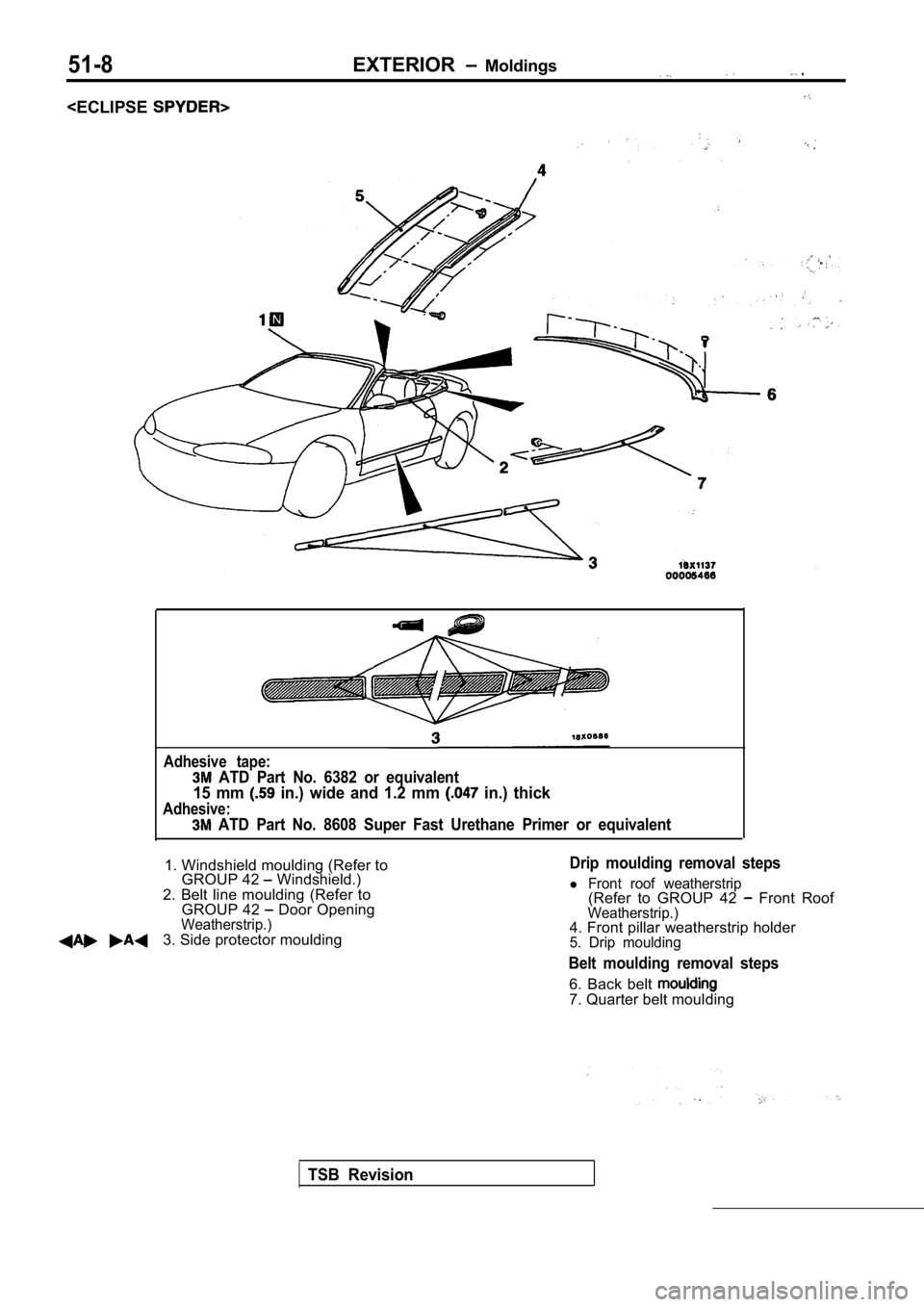
Adhesive tape:
ATD Part No. 6382 or equivalent
15 mm in.) wide and 1.2 mm in.) thick
Adhesive:
ATD Part No. 8608 Super Fast Urethane Primer or equivalent
1. Windshield moulding (Refer to
GROUP 42 Windshield.)
2. Belt line moulding (Refer to GROUP 42
Door OpeningWeatherstrip.)3. Side protector moulding
Drip moulding removal steps
l Front roof weatherstrip(Refer to GROUP 42 Front RoofWeatherstrip.)4. Front pillar weatherstrip holder5. Drip moulding
Belt moulding removal steps
6. Back belt 7. Quarter belt moulding
TSB Revision
Page 1959 of 2103
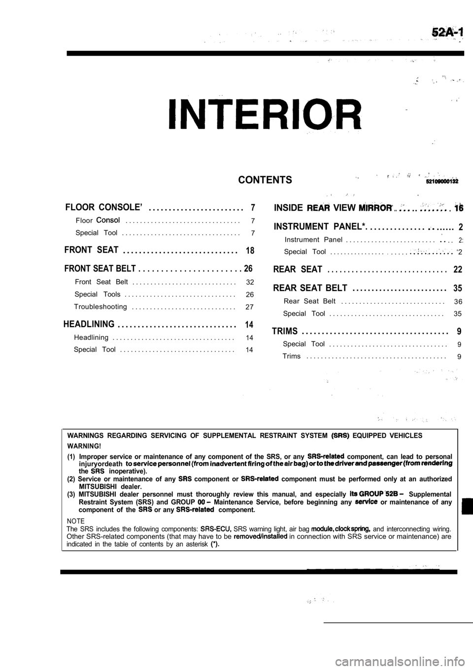
CONTENTS
FLOOR CONSOLE’. . . . . . . . . . . . . . . . . . . . . . . .7INSIDE VIEW .....
Floor. . . . . . . . . . . . . . . . . . . . . . . . . . . . . . . .7INSTRUMENT PANEL*.. . . . . . . . . . . . . .......2Special Tool . . . . . . . . . . . . . . . . . . . . . . . . . . . . . . . . . 7
Instrument Panel . . . . . . . . . . . . . . . . . . . . . . . . .. .2:
FRONT SEAT. . . . . . . . . . . . . . . . . . . . . . . . . . . . .18Special Tool. . . . . . . . . . . . . . . ... . . . .. ‘2
FRONT SEAT BELT . . . . . . . . . . . . . . . . . . . . . . . 26REAR SEAT. . . . . . . . . . . . . . . . . . . . . . . . . . . . . .22
Front Seat Belt
. . . . . . . . . . . . . . . . . . . . . . . . . . . . . 32REAR SEAT BELT. . . . . . . . . . . . . . . . . . . . . . . . .35Special Tools . . . . . . . . . . . . . . . . . . . . . . . . . . . . . . .
26
3 6
Troubleshooting Rear Seat Belt
. . . . . . . . . . . . . . . . . . . . . . . . . . . . .
. . . . . . . . . . . . . . . . . . . . . . . . . . . . . 27
Special Tool . . . . . . . . . . . . . . . . . . . . . . . . . . . . . . . . 35
HEADLINING. . . . . . . . . . . . . . . . . . . . . . . . . . . . . .14TRIMS. . . . . . . . . . . . . . . . . . . . . . . . . . . . . . . . . . . . .9Headlining . . . . . . . . . . . . . . . . . . . . . . . . . . . . . . . . . .14Special Tool. . . . . . . . . . . . . . . . . . . . . . . . . . . . . . . . .9Special Tool . . . . . . . . . . . . . . . . . . . . . . . . . . . . . . . .14Trims. . . . . . . . . . . . . . . . . . . . . . . . . . . . . . . . . . . . . . .
9
WARNINGS REGARDING SERVICING OF SUPPLEMENTAL RESTRA INT SYSTEM EQUIPPED VEHICLES
WARNING!
(1)
Improper service or maintenance of any component of the SRS, or any component, can lead to personal
injuryordeath
the inoperative).
(2) Service or maintenance of any component or component must be performed only at an authorized
MITSUBISHI dealer.
(3) MITSUBISHI dealer personnel must thoroughly rev iew this manual, and especially
Supplemental
Restraint System (SRS) and GROUP Maintenance Service, before beginning any or maintenance of any
component of the or any component.
NOTEThe SRS includes the following components: SRS warning light, air bag and interconnecting wiring.Other SRS-related components (that may have to be in connection with SRS service or maintenance) areindicated in the table of contents by an asterisk
Page 1967 of 2103
INTERIOR Trims
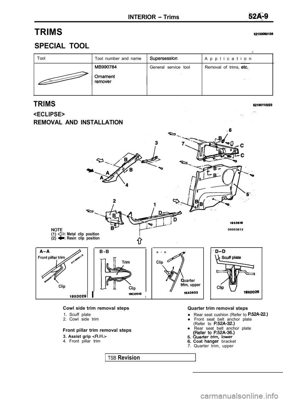
TRIMS
SPECIAL TOOL
ToolTool number and nameA p p l i c a t i o n
General service tool Removal of trims,
TRIMS
REMOVAL AND INSTALLATION
Metal clip position
Resin clip position
00003812
B - B
Cliplip
II
Cowl side trim removal steps 1. Scuff plate
2. Cowl side trim
Front pillar trim removal steps 3. Assist grip
4. Front pillar trim c - c
Clip
Quarter
trim, upper
Quarter trim removal steps
l Rear seat cushion (Refer to
l Front seat belt anchor plate
(Refer to
l Rear seat belt anchor plate
Coat bracket
7. Quarter trim, upper
TSBRevision
Page 1969 of 2103
N O T E
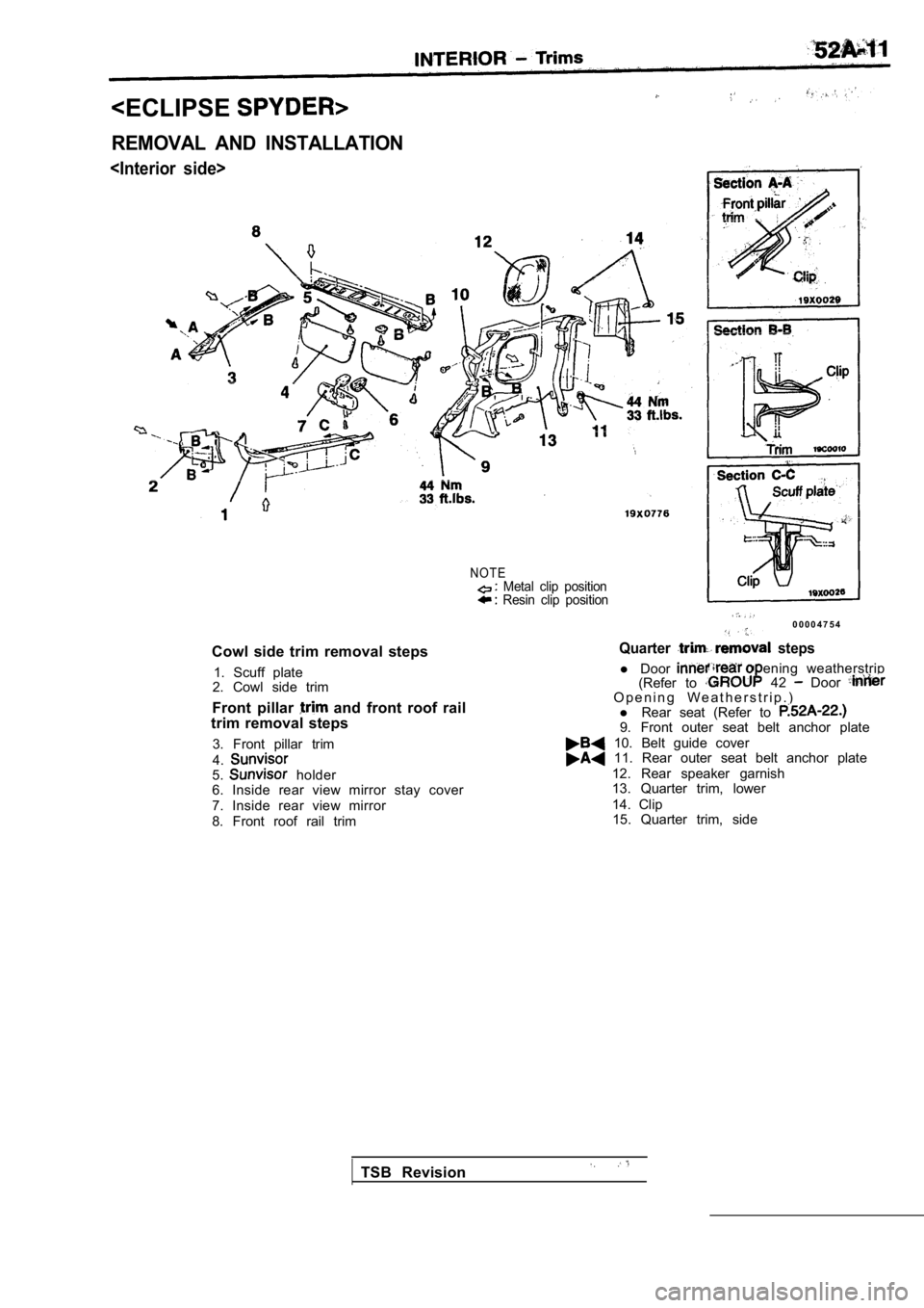
Cowl side trim removal steps1. Scuff plate
2. Cowl side trim
Front pillar
and front roof rail
trim removal steps
3. Front pillar trim
4.
5. holder
6. Inside rear view mirror stay cover
7. Inside rear view mirror
8. Front roof rail trim
Metal clip position Resin clip position
0 0 0 0 4 7 5 4
Quarter steps
l Door(Refer to ening weatherstrip
42 Door O p e n i n g W e a t h e r s t r i p . )
l Rear seat (Refer to
9. Front outer seat belt anchor plate
10. Belt guide cover 11. Rear outer seat belt anchor plate
12. Rear speaker garnish
13. Quarter trim, lower
14. Clip15. Quarter trim, side
TSB Revision
Page 1971 of 2103
lower
Belt guide
cover
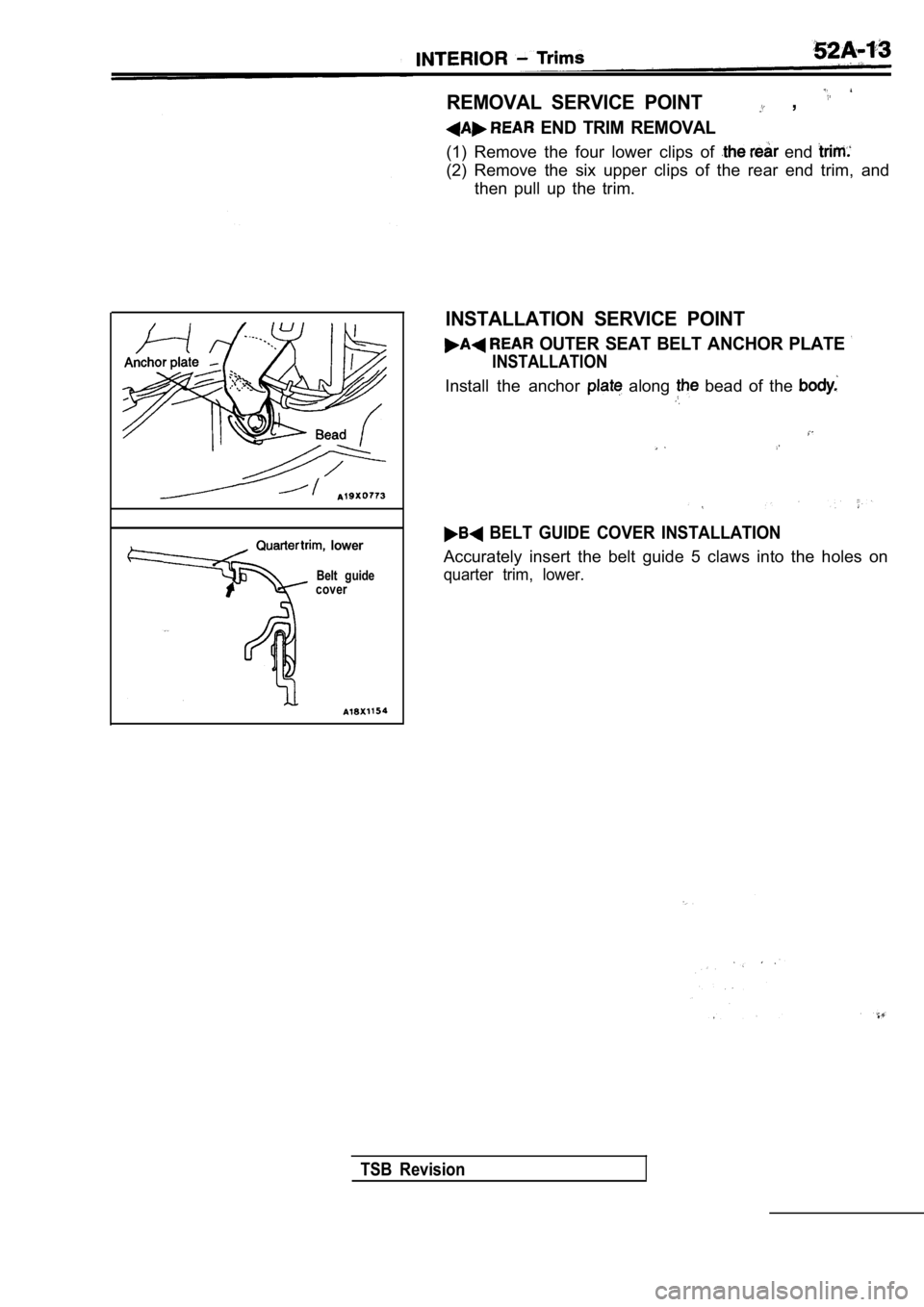
REMOVAL SERVICE POINT ,
END TRIM REMOVAL
(1) Remove the four lower clips of end
(2) Remove the six upper clips of the rear end trim , and
then pull up the trim.
INSTALLATION SERVICE POINT
OUTER SEAT BELT ANCHOR PLATE
INSTALLATION
Install the anchor along bead of the
BELT GUIDE COVER INSTALLATION
Accurately insert the belt guide 5 claws into the h oles on
quarter trim, lower.
TSB Revision
Page 1978 of 2103
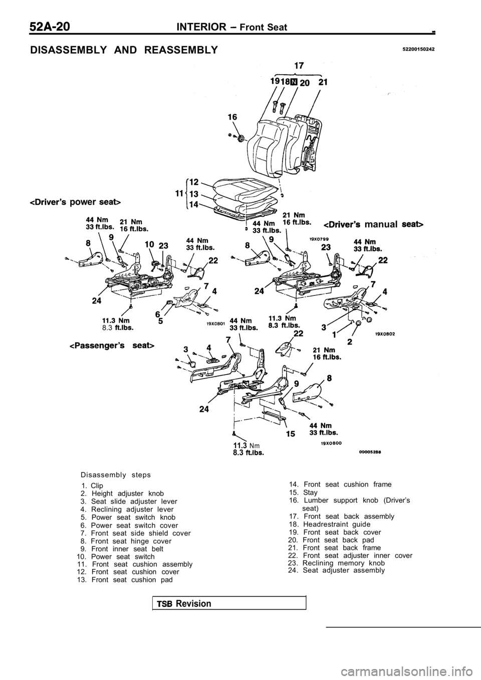
INTERIOR Front Seat
DISASSEMBLY AND REASSEMBLY52200150242
power
manual
8.3
11.3Nm8.3
D i s a s s e m b l y s t e p s1. Clip
2. Height adjuster knob
3. Seat slide adjuster lever
4. Reclining adjuster lever 5. Power seat switch knob
6. Power seat switch cover
7. Front seat side shield cover
8. Front seat hinge cover
9. Front inner seat belt
10. Power seat switch 11. Front seat cushion assembly
12. Front seat cushion cover
13. Front seat cushion pad 14. Front seat cushion frame
15. Stay
16. Lumber support knob (Driver’s
seat)
17. Front seat back assembly
18. Headrestraint guide
19. Front seat back cover
20. Front seat back pad
21. Front seat back frame
22. Front seat adjuster inner cover
23. Reclining memory knob 24. Seat adjuster assembly
Revision
Page 1981 of 2103
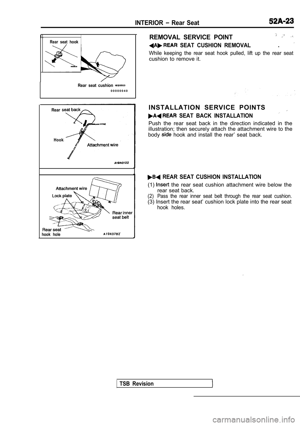
INTERIOR Rear Seat
Rear seat hook
Rear seat cushion 0 0 0 0 0 0 4 0
Rear
Hook
hook hole
REMOVAL SERVICE POINT
SEAT CUSHION REMOVAL.
While keeping the rear seat hook pulled, lift up the rear seat
cushion to remove it.
INSTALLATION SERVICE POINTS
SEAT BACK INSTALLATION
Push the rear seat back in the direction indicated in the
illustration; then securely attach the attachment w ire to the
body
hook and install the rear’ seat back.
REAR SEAT CUSHION INSTALLATION
(1) the rear seat cushion attachment wire below the
rear seat back.
(2) Pass the rear inner seat belt through the rear s eat cushion.
(3) Insert the rear seat’ cushion lock plate into the rear seat
hook holes.
TSB Revision