belt MITSUBISHI SPYDER 1990 Service Repair Manual
[x] Cancel search | Manufacturer: MITSUBISHI, Model Year: 1990, Model line: SPYDER, Model: MITSUBISHI SPYDER 1990Pages: 2103, PDF Size: 68.98 MB
Page 1807 of 2103
STEERING Power Steering Oil Pump
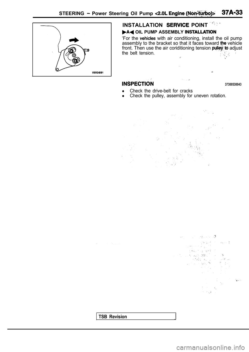
INSTALLATION POINT
OIL PUMP ASSEMBLY
‘For the with air conditioning, install the oil pump
assembly to the bracket so that it faces toward
vehicle
front. Then use the air coriditioning tension
adjust
the belt tension..
37300530043
Check the drive-belt for cracks
Check the pulley, assembly for uneven rotation.
TSB Revision
Page 1813 of 2103
P o w e r O i l P u m p ,
(TURBO) AND ENGINE>
.
, ,
OperationPower Steering Fluid Draining(Refer to
1316
28 Nm21
21
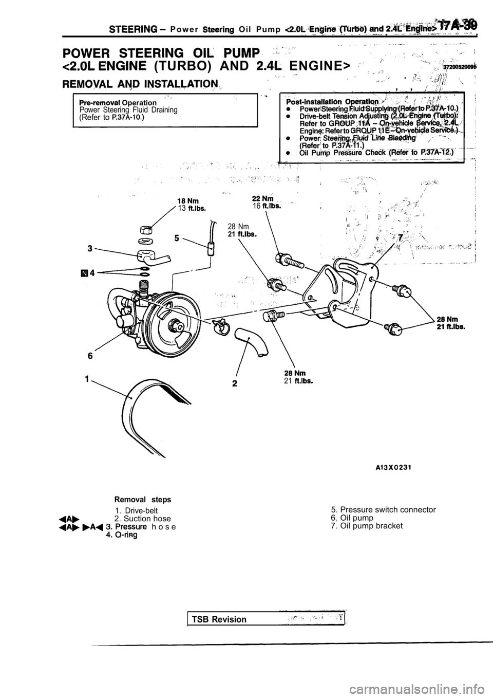
Removal steps
1. Drive-belt2. Suction hose h o s e
.
5. Pressure switch connector
6. Oil pump
7. Oil pump bracket
TSB Revision
Page 1814 of 2103
STEERING Power Steering Pump Engine (Turbo) and Engine>
Suction
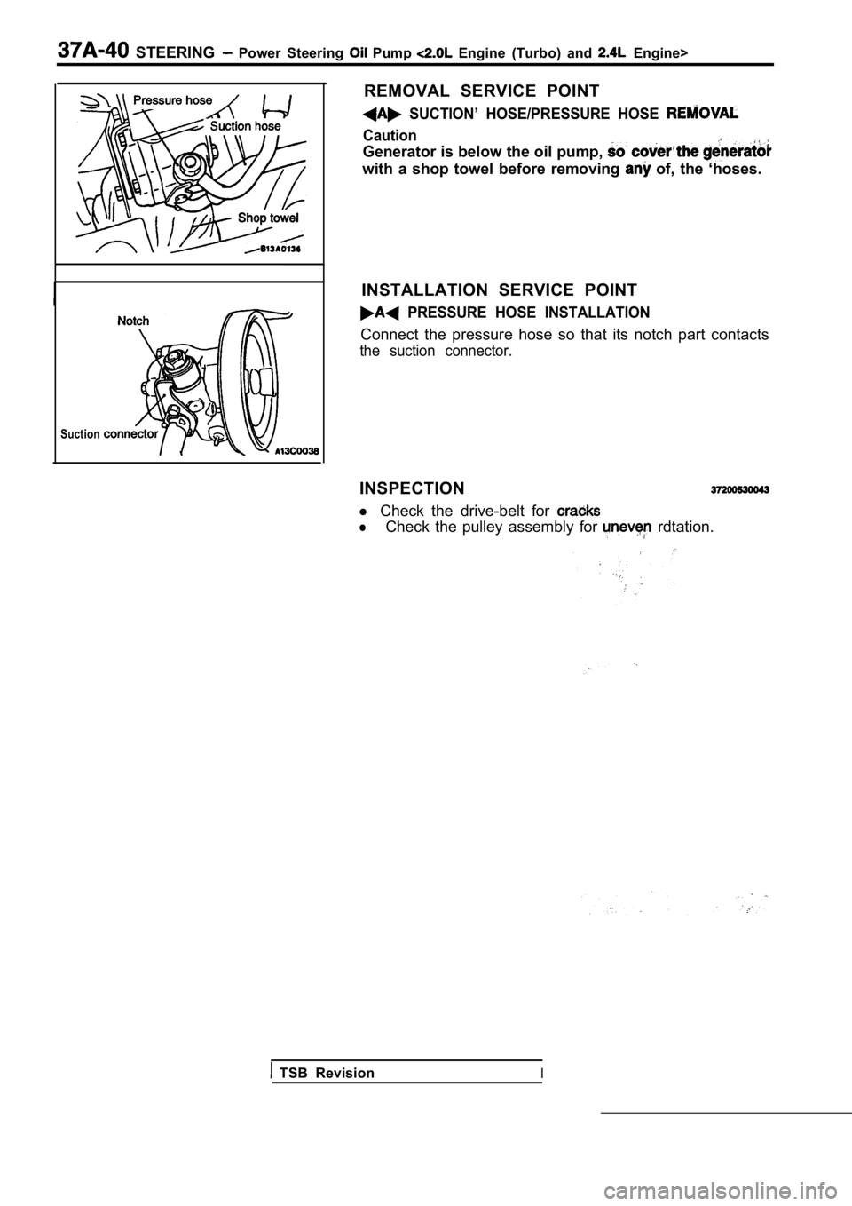
REMOVAL SERVICE POINT
SUCTION’ HOSE/PRESSURE HOSE
Caution
Generator is below the oil pump,
with a shop towel before removing of, the ‘hoses.
INSTALLATION SERVICE POINT
PRESSURE HOSE INSTALLATION
Connect the pressure hose so that its notch part co ntacts
the suction connector.
INSPECTION
l Check the drive-belt for
lCheck the pulley assembly for rdtation.
TSB RevisionI
Page 1821 of 2103
STEERING Power Steering Hoses Engine (Turbo) and
POWER STEERING HOSES
ENGINE (TURBO) AND ENGINE>
REMOVAL AND INSTALLATION
Post-installation Operationl Front Bumper Installation(Refer to GROUP 51 Front Bumper.)lDrive-belt Tension Adjustment Engine (Turbo):Refer to GROUP On-vehicle Service, Engine: Refer to GROUP 11 E-On-vehicle Service.)lPower Steering Fluid Supplying l Power Steering Fluid Line Bleeding (Refer to
23-26 Nm
34 Nm
25
11 Nm 11 Nm88
118
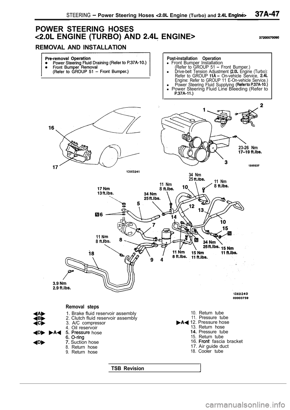
Removal steps
1. Brake fluid reservoir assembly
2. Clutch fluid reservoir assembly
3. A/C compressor4.Oil reservoir
hose
Suction hose
8.Return hose
9.Return hose
10.Return tube11.Pressure tube 12. Pressure hose13.Return hosePressure tube
15.Return tube16. fascia bracket
17. Air guide duct
18.Cooler tube
TSB Revision
Page 1831 of 2103
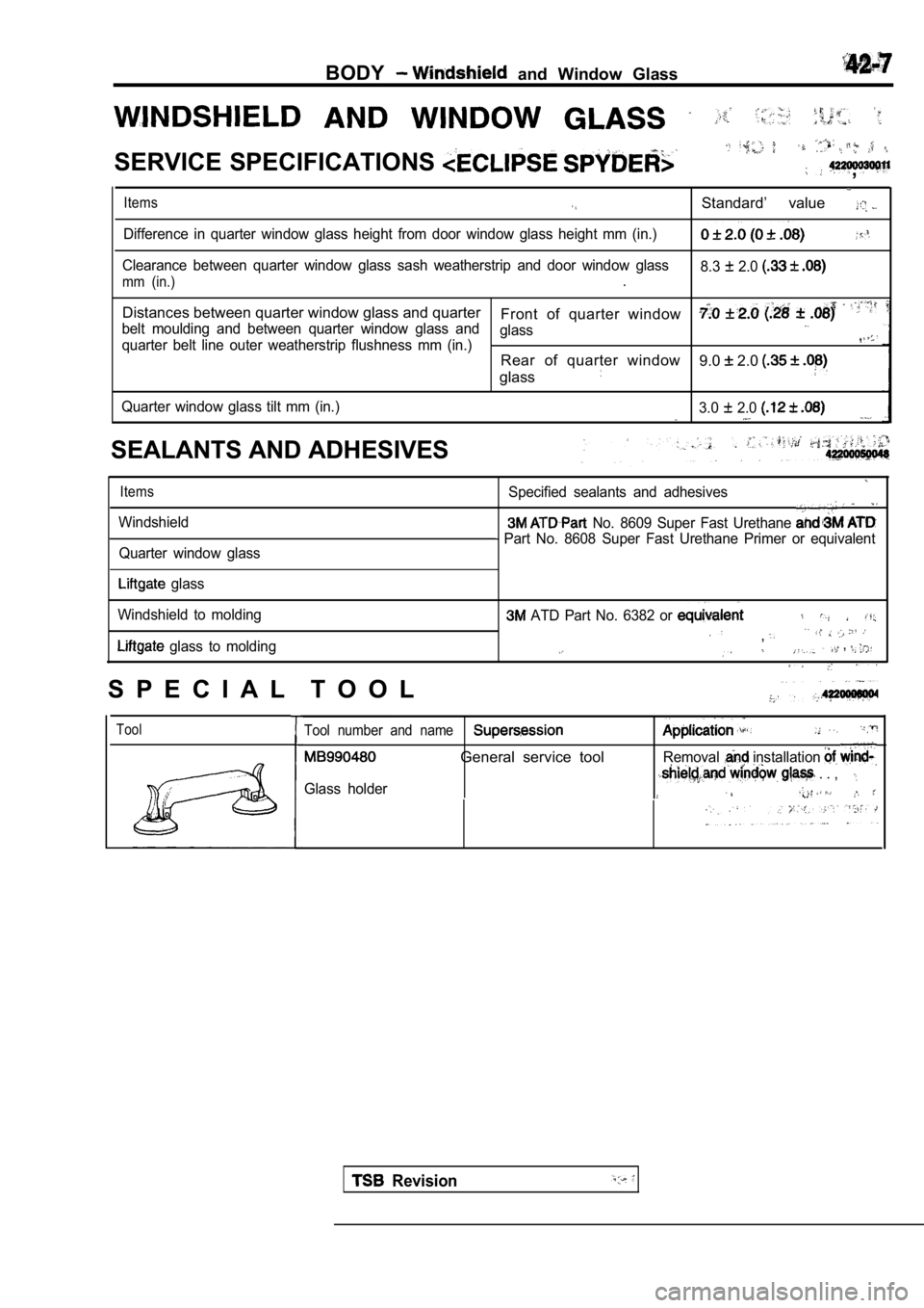
BODY and Window Glass
SERVICE SPECIFICATIONS ,
Items
Difference in quarter window glass height from door window glass height mm (in.)
Clearance between quarter window glass sash weather strip and door window glass
mm (in.).Standard’ value 8.3 2.0
Distances between quarter window glass and quarter
Front of quarter window
belt moulding and between quarter window glass and glass
quarter belt line outer weatherstrip flushness mm (in.)Rear of quarter window
glass9.0 2.0
Quarter window glass tilt mm (in.) 3.0 2.0
SEALANTS AND ADHESIVES
Items
Windshield
Quarter window glass
Specified sealants and adhesives
No. 8609 Super Fast Urethane
Part No. 8608 Super Fast Urethane Primer or equiva lent
glass
Windshield to molding
glass to molding
ATD Part No. 6382 or
,. . , . .
S P E C I A L T O O L
ToolTool number and name
General service toolRemoval installation
Glass holder . . ,
Revision
Page 1837 of 2103
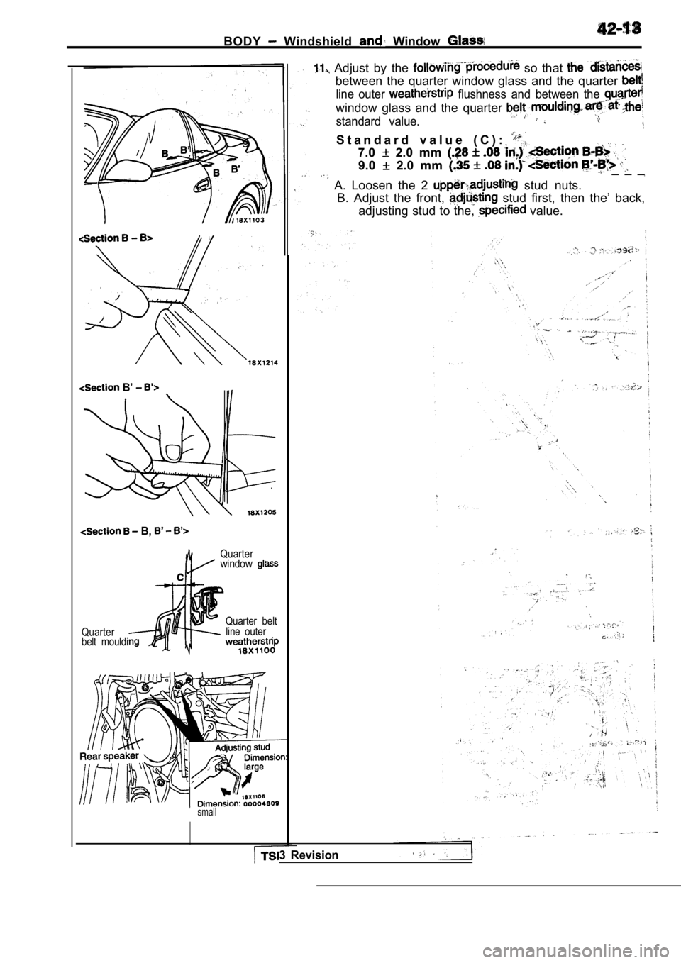
BODY Windshield Window
Adjust by the so that
between the quarter window glass and the quarter
line outer flushness and between the
window glass and the quarter
standard value.
B’
B,
Quarterwindow
Quarter
belt mouldiQuarter belt
line outer
small
S t a n d a r d v a l u e ( C ) :
7.0 2.0 mm
9.0 2.0 mm _ _ _
A. Loosen the 2 stud nuts.
B. Adjust the front, stud first, then the’ back,
adjusting stud to the,
value.
3 Revision
Page 1850 of 2103
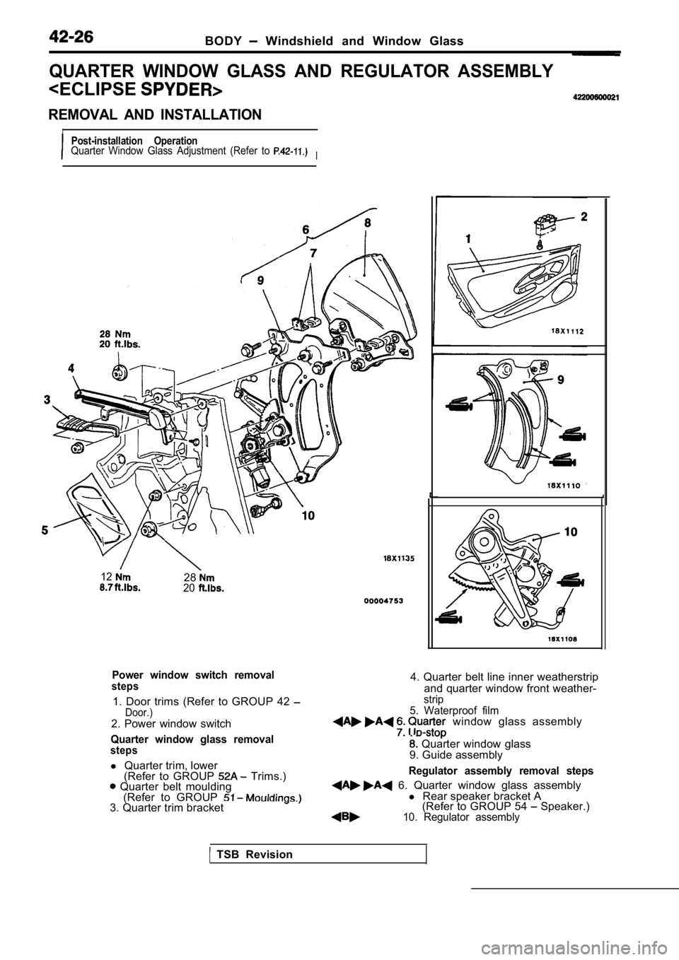
BODY Windshield and Window Glass
QUARTER WINDOW GLASS AND REGULATOR ASSEMBLY
IPost-installation OperationQuarter Window Glass Adjustment (Refer to I
122820
Power window switch removalsteps
1. Door trims (Refer to GROUP 42 Door.)2. Power window switch
Quarter window glass removalsteps
l Quarter trim, lower
(Refer to GROUP Trims.) Quarter belt moulding (Refer to GROUP
3. Quarter trim bracket
4. Quarter belt line inner weatherstrip
and quarter window front weather-
strip
5. Waterproof film
window glass assembly
Quarter window glass
9. Guide assembly
Regulator assembly removal steps
6. Quarter window glass assembly l Rear speaker bracket A
(Refer to GROUP 54 Speaker.)10. Regulator assembly
TSB Revision
Page 1872 of 2103
42-48BODY Door
Delta sashInner stabilizer
track
ON-VEHICLE SERVICE
DOOR FIT ADJUSTMENT
1.Use the special tool to loosen the hinge mounting b
olts
o n t h e b o d y
2. When there is a stepped section in the door and body,
use the special
loosen the door hinge mounting
bolt on the door side and adjust the door fit.
Caution
Attach protection tape to the fender. edges
the
hinge is installed.
3. If the door is hard to open or close, use the sh im or
move the striker up and down or left and right to a djust
the linking of the striker and the door latch.
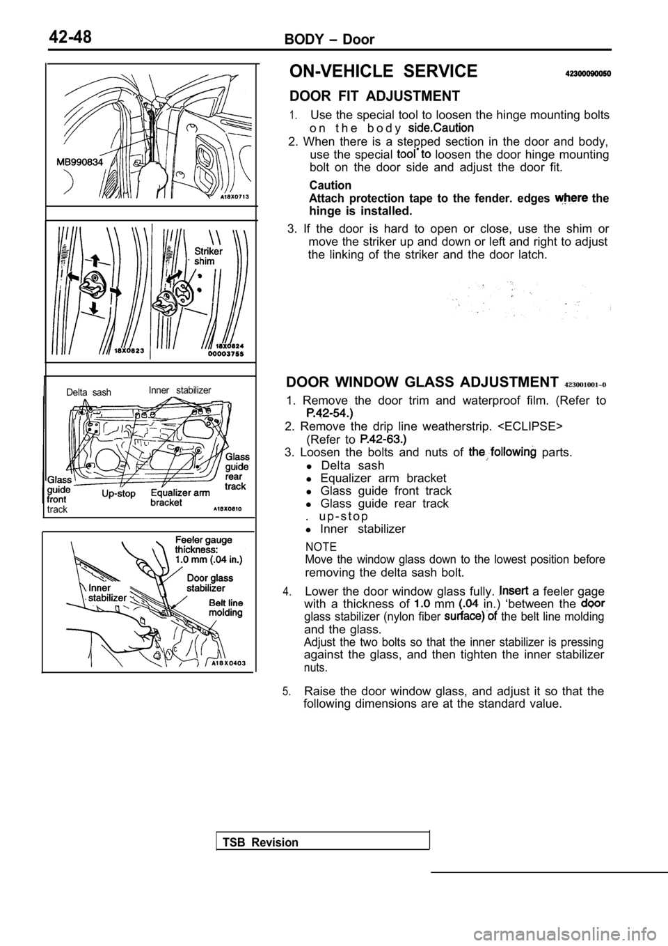
DOOR WINDOW GLASS ADJUSTMENT 423001001~0
1. Remove the door trim and waterproof film. (Refer to
2. Remove the drip line weatherstrip.
(Refer to
3. Loosen the bolts and nuts of parts.
l Delta sash
l Equalizer arm bracket
l Glass guide front track
l Glass guide rear track
. u p - s t o p
l Inner stabilizer
NOTE
Move the window glass down to the lowest position b efore
removing the delta sash bolt.
4.Lower the door window glass fully. a feeler gage
with a thickness of
mm in.) ‘between the
glass stabilizer (nylon fiber the belt line molding
and the glass.
Adjust the two bolts so that the inner stabilizer i s pressing
against the glass, and then tighten the inner stabi lizer
nuts.
5.Raise the door window glass, and adjust it so that the
following dimensions are at the standard value.
TSB Revision
Page 1874 of 2103
Section A-A
Section B-B
Section C-C
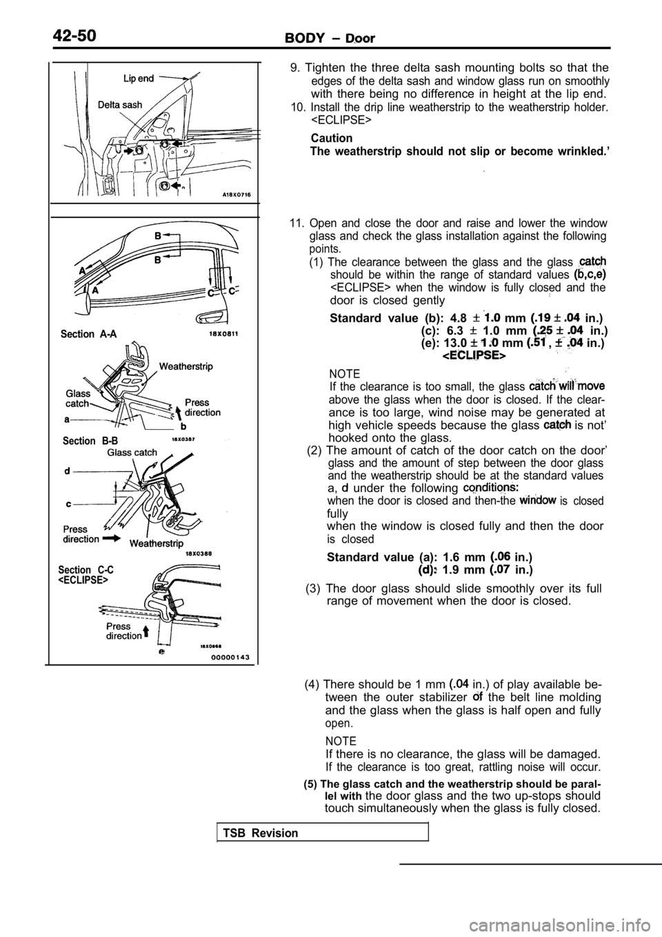
9. Tighten the three delta sash mounting bolts so t hat the
edges of the delta sash and window glass run on smo othly
with there being no difference in height at the lip end.
10. Install the drip line weatherstrip to the weatherstrip holder.
Caution
The weatherstrip should not slip or become wrinkled .’
11. Open and close the door and raise and lower the window
glass and check the glass installation against the following
points.
(1) The clearance between the glass and the glass
should be within the range of standard values
door is closed gently
Standard value (b): 4.8 mm in.)
(c): 6.3
1.0 mm in.)
(e): 13.0
mm , in.)
NOTE
If the clearance is too small, the glass
above the glass when the door is closed. If the cle ar-
ance is too large, wind noise may be generated at
high vehicle speeds because the glass
is not’
hooked onto the glass.
(2) The amount of catch of the door catch on the do or’
glass and the amount of step between the door glass
and the weatherstrip should be at the standard valu es
a, under the following
when the door is closed and then-the is closed
fully
when the window is closed fully and then the door
is closed
Standard value (a): 1.6 mm in.)
1.9 mm in.)
(3) The door glass should slide smoothly over its f ull
range of movement when the door is closed.
(4) There should be 1 mm
in.) of play available be-
tween the outer stabilizer
the belt line molding
and the glass when the glass is half open and fully
open.
NOTE
If there is no clearance, the glass will be damaged .
If the clearance is too great, rattling noise will occur.
(5) The glass catch and the weatherstrip should be paral-
lel with the door glass and the two up-stops should
touch simultaneously when the glass is fully closed .
TSB Revision
Page 1880 of 2103
BODY Door
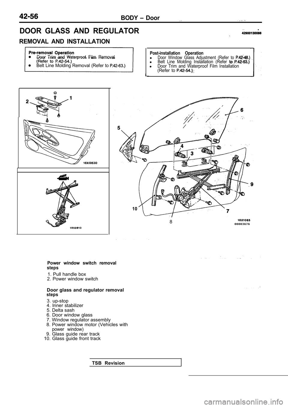
DOOR GLASS AND REGULATOR
REMOVAL AND INSTALLATION
.
Door Trim and Film Removal
Belt Line Molding Removal (Refer to
10
Post-installation OperationlDoor Window Glass Adjustment (Refer to lBelt Line Molding Installation (Refer lDoor Trim and Waterproof Film Installation(Refer to
TSB Revision8
0 0 0 0 3 6 7 6
Power window switch removalsteps
1. Pull handle box
2. Power window switch
Door glass and regulator removal
steps
3. up-stop
4. Inner stabilizer
5. Delta sash
6. Door window glass
7. Window regulator assembly
8. Power window motor (Vehicles with
power window)9. Glass guide rear track
10. Glass guide front track