torque MITSUBISHI SPYDER 1990 Service User Guide
[x] Cancel search | Manufacturer: MITSUBISHI, Model Year: 1990, Model line: SPYDER, Model: MITSUBISHI SPYDER 1990Pages: 2103, PDF Size: 68.98 MB
Page 67 of 2103
ENGINE On-vehicle
98 (22
Generator
pulley
pulley
v
pulley
ON-VEHICLE
DRIVE BELT TENSION CHECK’ AND
ADJUSTMENT
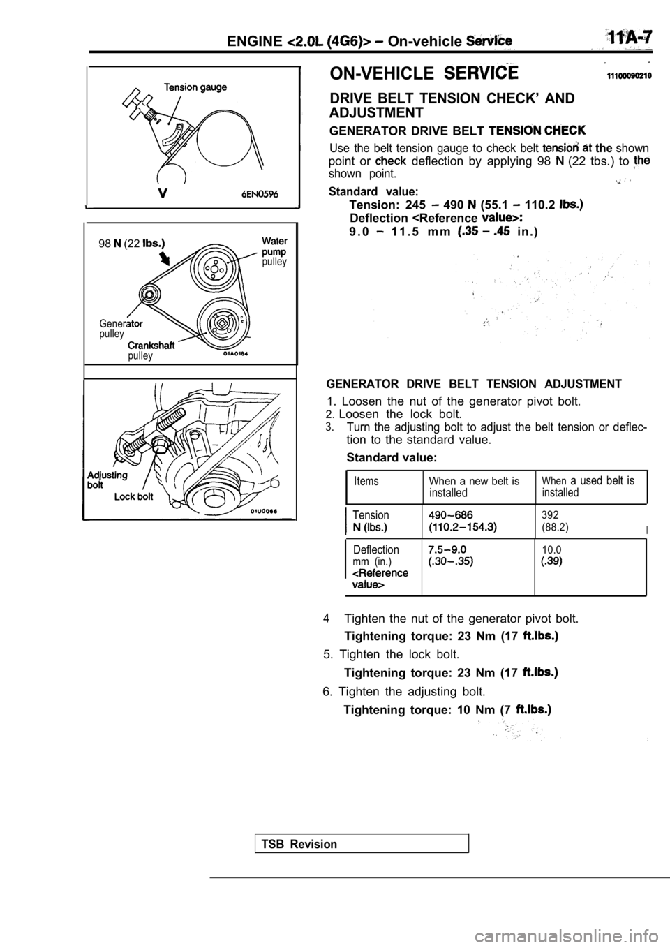
GENERATOR DRIVE BELT
Use the belt tension gauge to check belt the shown
point or deflection by applying 98 (22 tbs.) to
shown point.
Standard value:
Tension: 245 490 (55.1 110.2
Deflection
GENERATOR DRIVE BELT TENSION ADJUSTMENT
1. Loosen the nut of the generator pivot bolt.
2. Loosen the lock bolt.
3.Turn the adjusting bolt to adjust the belt tension or deflec-
tion to the standard value.
Standard value:
ItemsWhen a new belt is
installed
Whena used belt is
installed
Tension392
(88.2)I
Deflection10.0
mm (in.)
4Tighten the nut of the generator pivot bolt.
Tightening torque: 23 Nm (17
5. Tighten the lock bolt.
Tightening torque: 23 Nm (17
6. Tighten the adjusting bolt.Tightening torque: 10 Nm (7
TSB Revision
Page 68 of 2103
ENGINE On-vehicle Service
pump pulley
Cranksh
pulley
pulley
a
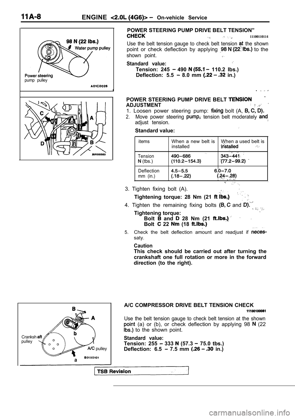
POWER STEERING PUMP DRIVE BELT TENSION”
11100110114
Use the belt tension gauge to check belt tension the shown
point or check deflection by applying to the
shown point.
Standard value:
Tension: 245 490 110.2 Ibs.)
Deflection: 5.5
8.0 mm in.)
.
POWER STEERING PUMP DRIVE BELT
ADJUSTMENT
1. Loosen power steering pump: bolt (A,
2.Move power steering tension belt moderately
adjust tension.
Standard value:
items
Tension
(tbs.)
Deflection
mm (in.)
When a new belt is When a used belt is installed
,,
3. Tighten fixing bolt (A).
Tightening torque: 28 Nm (21
4. Tighten the remaining fixing bolts and
Tightening torque:
Bolt and 28 Nm (21
Bolt 22 (18
5.Check the belt deflection amount and readjust if
saty.
Caution
This check should be carried out after turning the
crankshaft one full rotation or more in the forward
direction (to the right).
A/C COMPRESSOR DRIVE BELT TENSION CHECK
Use the belt tension gauge to check belt tension at the shown
(a) or (b), or check deflection by applying 98 (22
to the shown point.
Standard value:
Tension: 255 333 (57.3 75.0 tbs.)
Deflection: 6.5
7.5 mm in.)
Page 69 of 2103
ENGINE On-vehicle
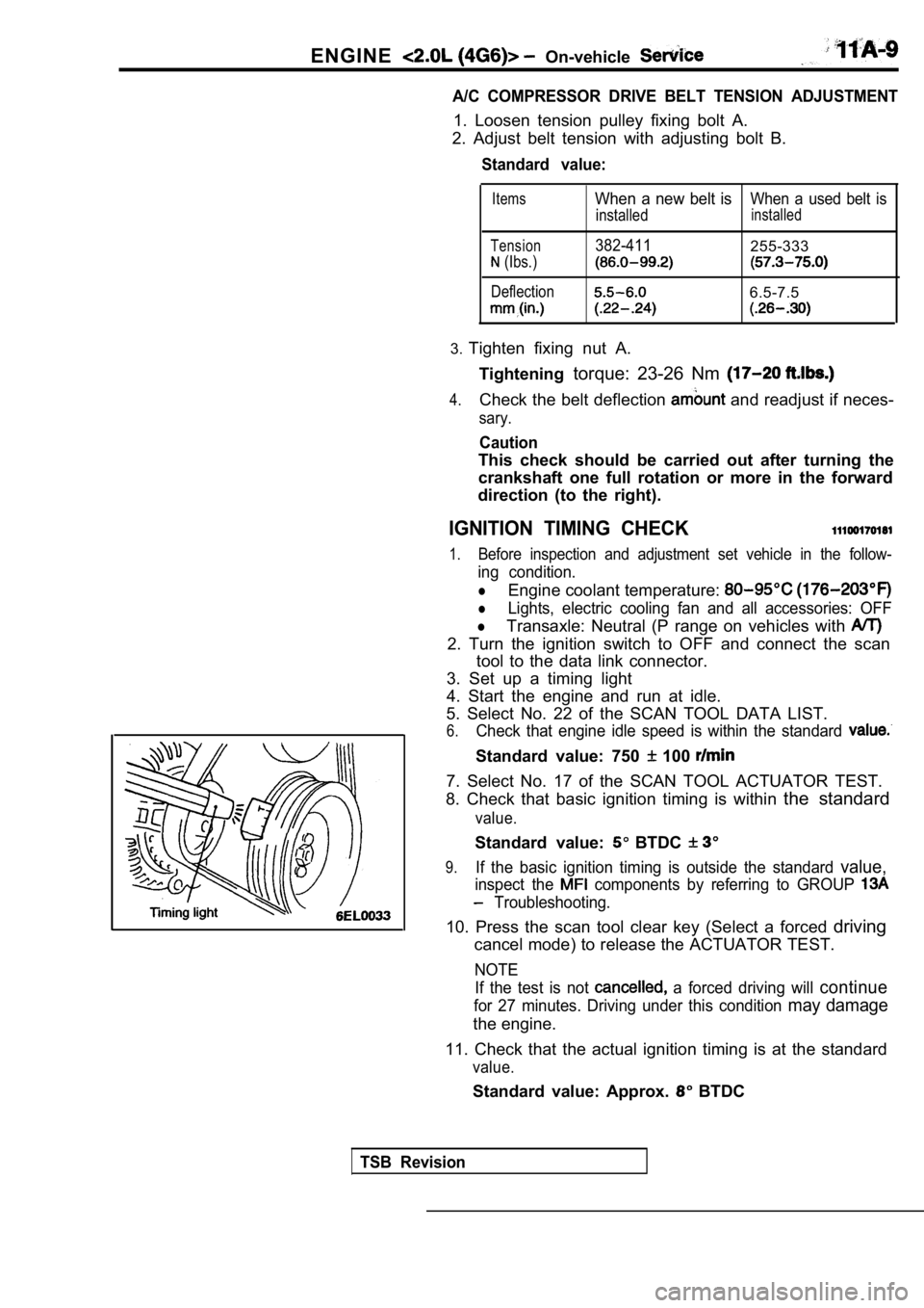
A/C COMPRESSOR DRIVE BELT TENSION ADJUSTMENT
1. Loosen tension pulley fixing bolt A.
2. Adjust belt tension with adjusting bolt B.
Standard value:
Items
Tension
(Ibs.)
Deflection
When a new belt isWhen a used belt is
installedinstalled
382-411255-333
6.5-7.5
3. Tighten fixing nut A.
Tightening torque: 23-26 Nm
4.Check the belt deflection and readjust if neces-
sary.
Caution
This check should be carried out after turning the
crankshaft one full rotation or more in the forward
direction (to the right).
IGNITION TIMING CHECK
1.Before inspection and adjustment set vehicle in the follow-
ing condition.
lEngine coolant temperature:
lLights, electric cooling fan and all accessories: OFF
lTransaxle: Neutral (P range on vehicles with
2. Turn the ignition switch to OFF and connect the scan
tool to the data link connector.
3. Set up a timing light
4. Start the engine and run at idle.
5. Select No. 22 of the SCAN TOOL DATA LIST.
6.Check that engine idle speed is within the standard
Standard value: 750 100
7. Select No. 17 of the SCAN TOOL ACTUATOR TEST.
8. Check that basic ignition timing is within the standard
value.
Standard value: BTDC
9.If the basic ignition timing is outside the standar d value,
inspect the components by referring to GROUP
Troubleshooting.
10. Press the scan tool clear key (Select a forced driving
cancel mode) to release the ACTUATOR TEST.
NOTE
If the test is not
a forced driving will continue
for 27 minutes. Driving under this condition may damage
the engine.
11. Check that the actual ignition timing is at the standard
value.
Standard value: Approx. BTDC
TSB Revision
Page 85 of 2103
ENGINECamshaft and Oil Seal
CAMSHAFT CAP
C A M S H A F T
BEARING CAP
INSTALLATION
Tighten the bearing cap installation bolts to the torque
in two or three steps.
C a u t i o n
Tighten uniformly, otherwise the rocker arms not
straight.
Camshaft position
Camshaft positionsensor paint
CAMSHAFT OIL SEAL INSTALLATION
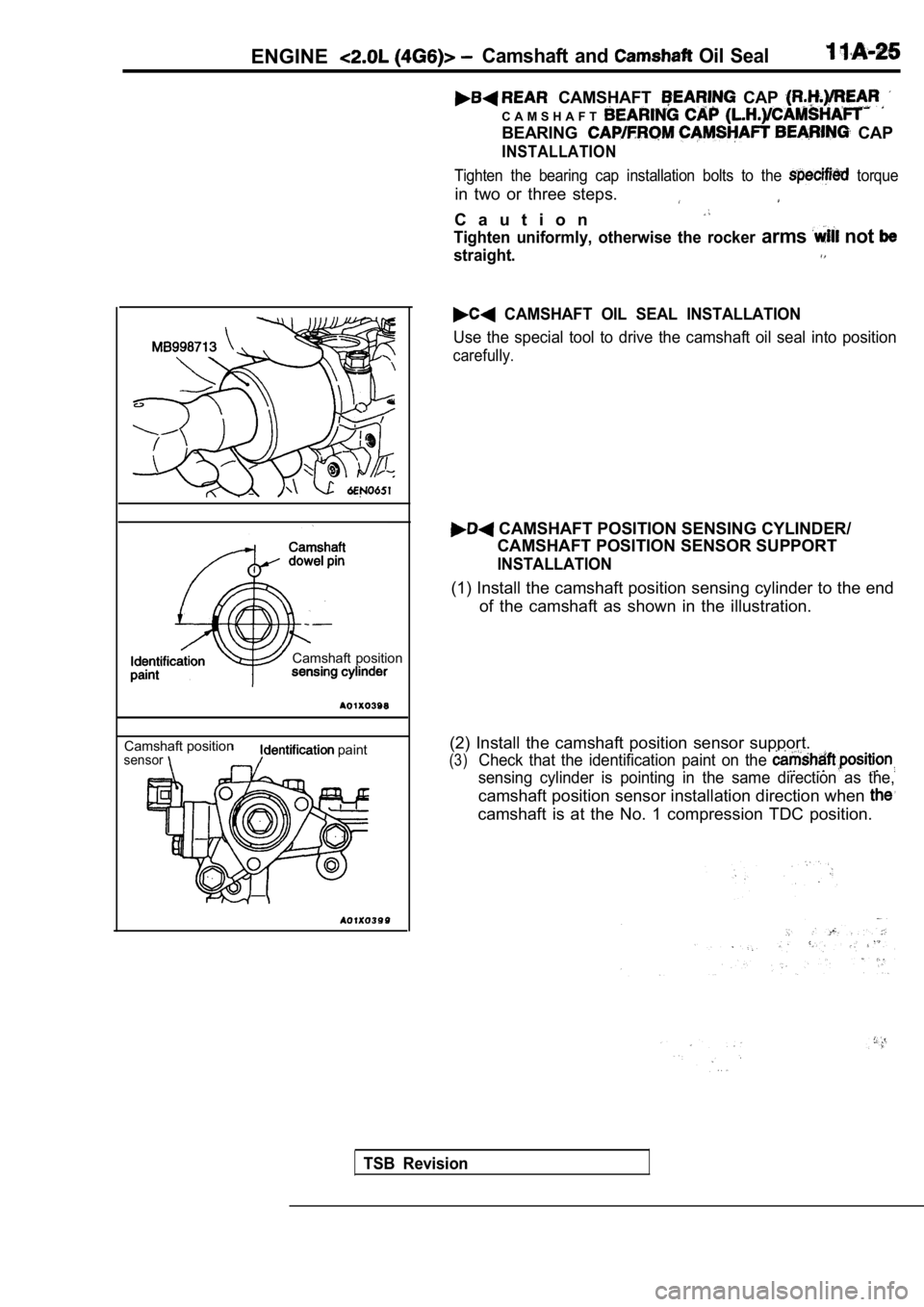
Use the special tool to drive the camshaft oil seal into position
carefully.
CAMSHAFT POSITION SENSING CYLINDER/
CAMSHAFT POSITION SENSOR SUPPORT
INSTALLATION
(1) Install the camshaft position sensing cylinder to the end
of the camshaft as shown in the illustration.
(2) Install the camshaft position sensor support.
(3)Check that the identification paint on the
sensing cylinder is pointing in the same direction as the,
camshaft position sensor installation direction when
camshaft is at the No. 1 compression TDC position.
TSB Revision
Page 90 of 2103
11ENGINE Crankshaft pear Oil
,
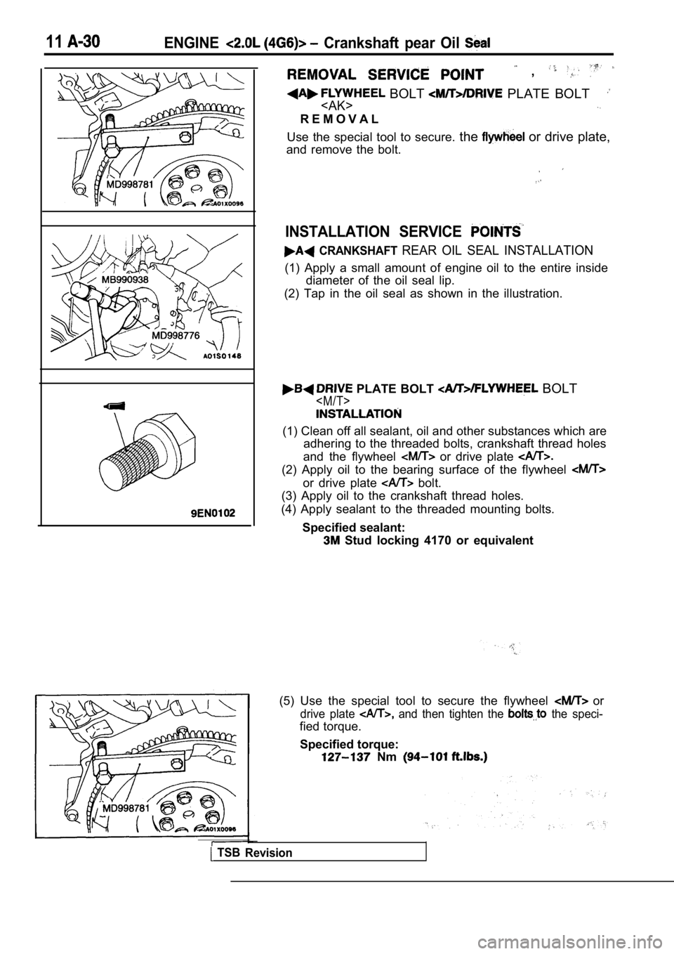
BOLT PLATE BOLT
R E M O V A L
Use the special tool to secure. the
or drive plate,
and remove the bolt.
INSTALLATION SERVICE
CRANKSHAFT REAR OIL SEAL INSTALLATION
(1) Apply a small amount of engine oil to the entir e inside
diameter of the oil seal lip.
(2) Tap in the oil seal as shown in the illustratio n.
PLATE BOLT BOLT
(1) Clean off all sealant, oil and other substances which are
adhering to the threaded bolts, crankshaft thread h oles
and the flywheel
or drive plate
(2) Apply oil to the bearing surface of the flywhee l
or drive plate bolt.
(3) Apply oil to the crankshaft thread holes.
(4) Apply sealant to the threaded mounting bolts.
Specified sealant:
Stud locking 4170 or equivalent
TSB Revision
(5) Use the special tool to secure the flywheel or
drive plate and then tighten the the speci-
fied torque.
Specified torque:
Nm
Page 99 of 2103
E N G I N E
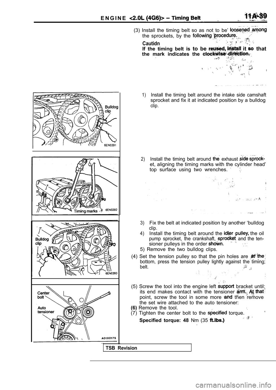
(3) Install the timing belt so as not to be’
the sprockets, by the
Cautidn ,
If the timing belt is to be it that
the mark indicates the
,
1)Install the timing belt around the intake side cams haft
sprocket and fix it at indicated position by a bulldog
clip.
2)Install the timing belt around exhaust
et, aligning the timing marks with the cylinder hea d’
top surface using two wrenches.
3)Fix the belt at indicated position by another ‘bull dog
clip.
4)
Install the timing belt around the the oil
pump sprocket, the crankshaft, and the ten-
sioner pulleys in the order
5) Remove the two bulldog clips.
(4) Set the tension pulley so that the pin holes ar e
bottom, press the tension pulley lightly against the timing;
belt.
(5) Screw the tool into the engine left bracket until:
its end makes contact with the tensioner
point, screw the tool in some more then remove
the set wire attached to the auto tensioner:
(6) Remove the tool.
(7) Tighten the center bolt to the
torque.
Specified torque: 48 Nm (35
TSB Revision
Page 100 of 2103
E N G I N E Belt
Auto tensioner
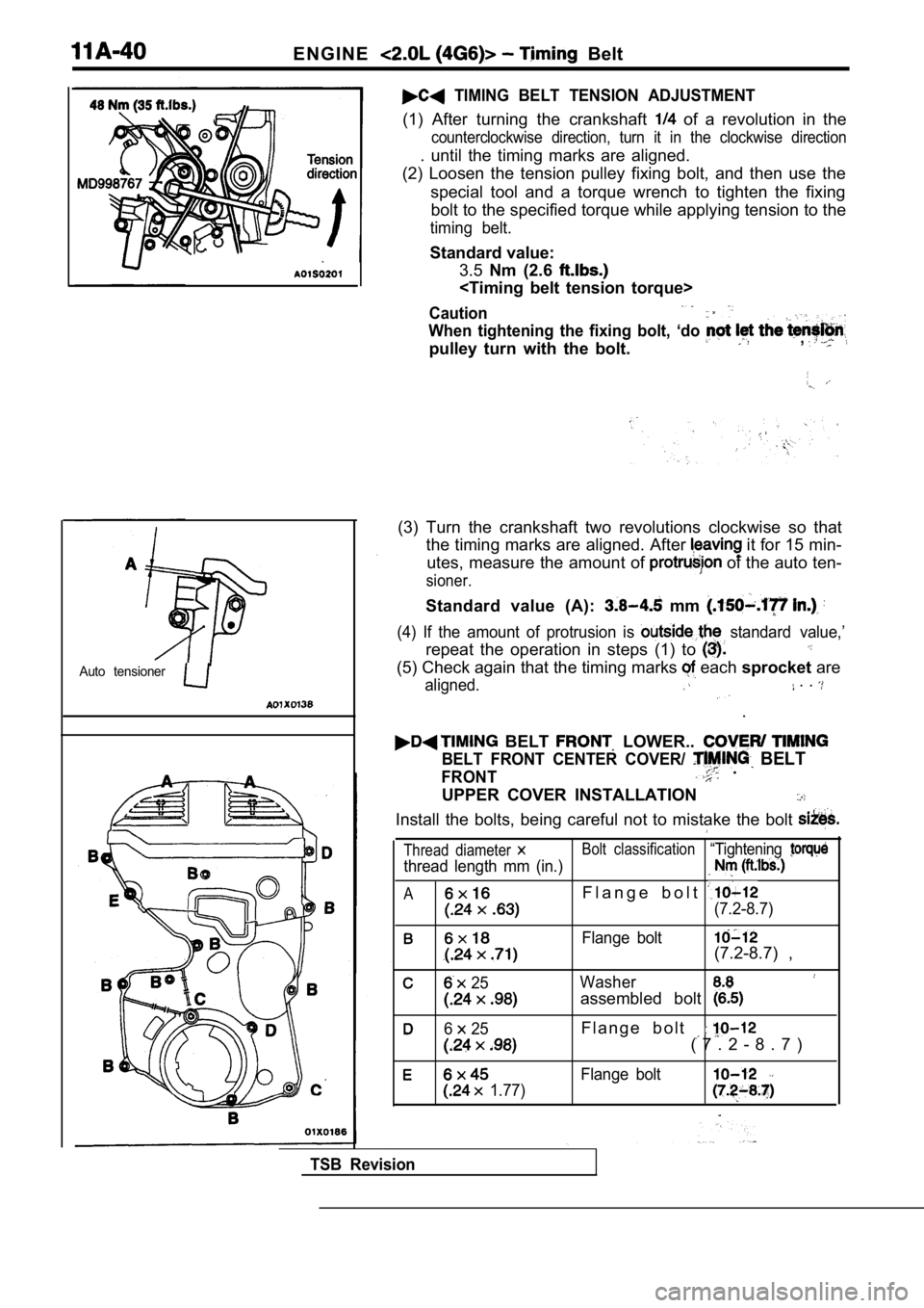
TIMING BELT TENSION ADJUSTMENT
(1) After turning the crankshaft of a revolution in the
counterclockwise direction, turn it in the clockwise direction
. until the timing marks are aligned.
(2) Loosen the tension pulley fixing bolt, and then use the
special tool and a torque wrench to tighten the fix ing
bolt to the specified torque while applying tension to the
timing belt.
Standard value:
3.5 Nm (2.6
Caution
When tightening the fixing bolt, ‘do
pulley turn with the bolt.,
(3) Turn the crankshaft two revolutions clockwise s o that
the timing marks are aligned. After
it for 15 min-
utes, measure the amount of
of the auto ten-
sioner.
Standard value (A): mm
(4) If the amount of protrusion is standard value,’
repeat the operation in steps (1) to
(5) Check again that the timing marks each sprocket are
aligned. . .
.
BELT LOWER..
BELT FRONT CENTER COVER/ BELT
FRONT .
UPPER COVER INSTALLATION
Install the bolts, being careful not to mistake the bolt
Thread diameter Bolt classification“Tightening
thread length mm (in.)
AF l a n g e b o l t
(7.2-8.7)
Flange bolt(7.2-8.7) ,
25Washer
assembled bolt
6 25F l a n g e b o l t
( 7 . 2 - 8 . 7 )
Flange bolt
1.77)
TSB Revision
Page 105 of 2103
CONTENTS
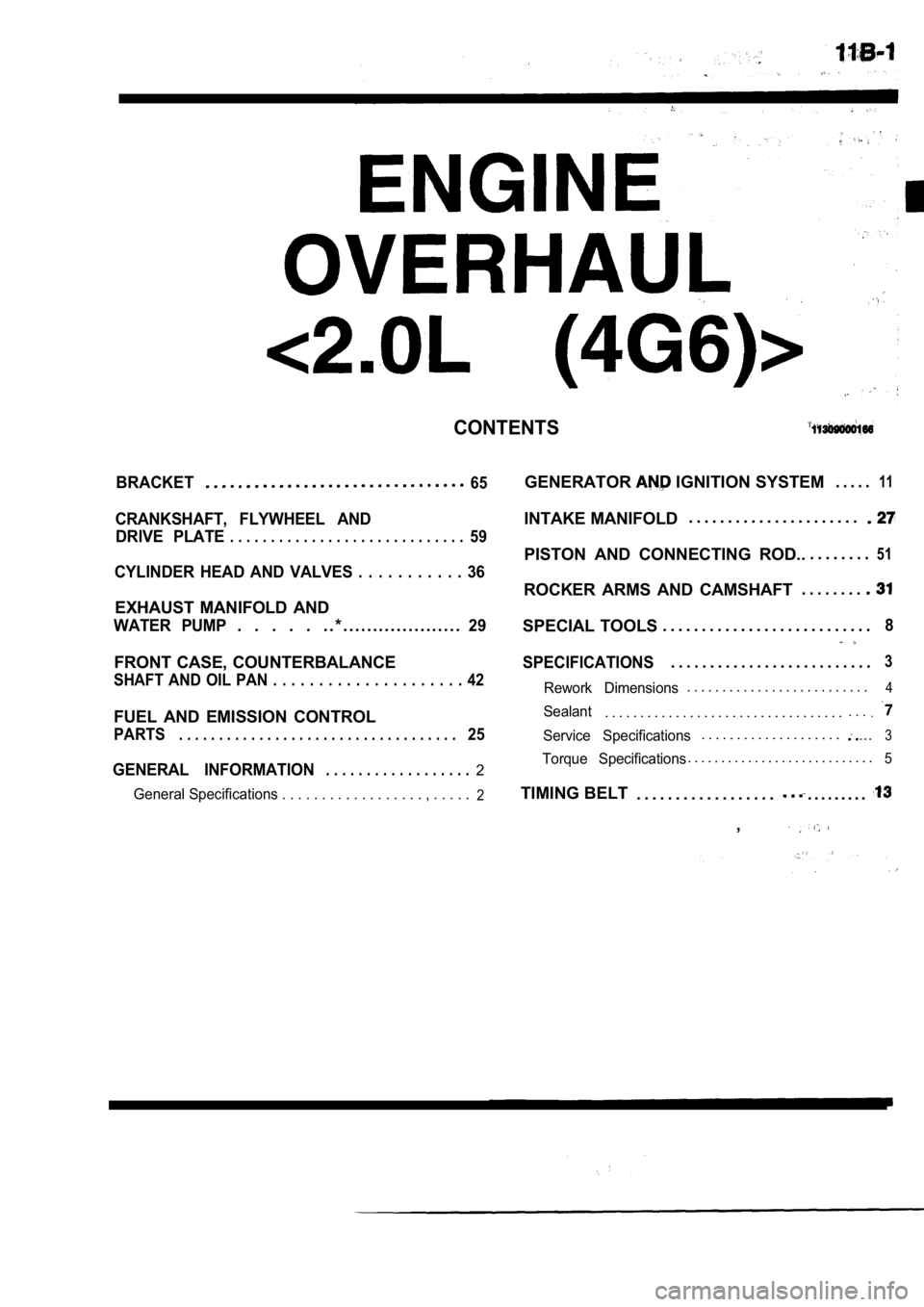
BRACKET65
CRANKSHAFT, FLYWHEEL ANDDRIVE PLATE
. . . . . . . . . . . . . . . . . . . . . . . . . . . . .59
CYLINDER HEAD AND VALVES . . . . . . . . . . . 36
EXHAUST MANIFOLD AND
WATER PUMP. . . . . . . * . . . . . . . . . . . . . . . . . . . .29
FRONT CASE, COUNTERBALANCE
SHAFT AND OIL PAN . . . . . . . . . . . . . . . . . . . . . 42
FUEL AND EMISSION CONTROL
PARTS. . . . . . . . . . . . . . . . . . . . . . . . . . . . . . . . . . .25
GENERAL INFORMATION. . . . . . . . . . . . . . . . . .2
General Specifications . . . . . . . . . . . . . . . . . . , . . . . .2
GENERATOR IGNITION SYSTEM. . . . .11
INTAKE MANIFOLD. . . . . . . . . . . . . . . . . . . . . .
PISTON AND CONNECTING ROD..
. . . . . . . .51
ROCKER ARMS AND CAMSHAFT. . . . . . . .
SPECIAL TOOLS
. . . . . . . . . . . . . . . . . . . . . . . . . . .8
SPECIFICATIONS. . . . . . . . . . . . . . . . . . . . . . . . . .3
Rework Dimensions. . . . . . . . . . . . . . . . . . . . . . . . . .4
Sealant. . . . . . . . . . . . . . . . . . . . . . . . . . . . . . . . . .. . ..
Service Specifications. . . . . . . . . . . . . . . . . . . ....3
Torque Specifications. . . . . . . . . . . . . . . . . . . . . . . . . . . .5
TIMING BELT
. . . . . . . . . . . . . . . . . .. . . . . . . . .
,
Page 109 of 2103
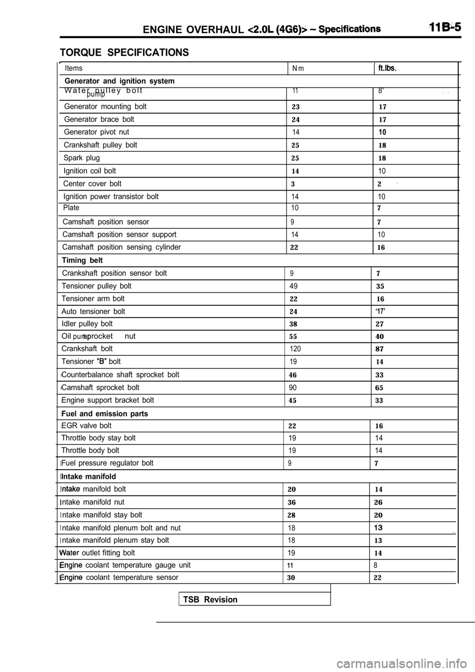
ENGINE OVERHAUL
TORQUE SPECIFICATIONS
, ,
I
I I
I
I I
I
I
I I
Items
Generator and ignition system
W a t e r p u l l e y b o l tpump
Generator mounting bolt
Generator brace bolt
Generator pivot nut
Crankshaft pulley bolt
Spark plug
Ignition coil bolt
Center cover bolt Ignition power transistor bolt
Plate
Camshaft position sensor
Camshaft position sensor support
Camshaft position sensing cylinder
Timing belt
Crankshaft position sensor bolt
Tensioner pulley bolt
Tensioner arm bolt
Auto tensioner bolt Idler pulley bolt
Oil sprocket nutpump
Crankshaft bolt
Tensioner
bolt
Counterbalance shaft sprocket bolt
Camshaft sprocket bolt
Engine support bracket bolt
Fuel and emission parts
EGR valve bolt
Throttle body stay bolt
Throttle body bolt
Fuel pressure regulator bolt
Intake manifold
manifold bolt
ntake manifold nut ntake manifold stay bolt
ntake manifold plenum bolt and nut
ntake manifold plenum stay bolt
outlet fitting bolt
coolant temperature gauge unit
coolant temperature sensor
TSB Revision
N m
118”
23 17
2417
1410
25 18
25 18
1410
32
1410
107
97
14 10
2216
97
4935
22 16
24
‘17’
3827
5540
12087
1914
4633
9065
45 33
22 16
19 14
1914
97
2014
3626
2820
18
1813
1914
118
30 22
Page 123 of 2103
![MITSUBISHI SPYDER 1990 Service User Guide ENGINE OVERHAUL Belt
Phillips screwdriver
BOLT
O I L S P R O C K E T
(1) a Phillips screwdriver [shank diameter 8 mm
in.) shaft] through the plug hole on the the
cylinde MITSUBISHI SPYDER 1990 Service User Guide ENGINE OVERHAUL Belt
Phillips screwdriver
BOLT
O I L S P R O C K E T
(1) a Phillips screwdriver [shank diameter 8 mm
in.) shaft] through the plug hole on the the
cylinde](/img/19/57345/w960_57345-122.png)
ENGINE OVERHAUL Belt
Phillips screwdriver
BOLT
O I L S P R O C K E T
(1) a Phillips screwdriver [shank diameter 8 mm
in.) shaft] through the plug hole on the the
cylinder block to block the left counterbalance sha ft.
(2)
the oil pump sprocket. .
(3) Apply a proper amount of engine oil-to the bearing
of the nuts.
(4) Tighten the nuts to the specified‘ torque.
AUTO TENSIONER INSTALLATION
(1) If the auto tensioner rod is in its fully exten ded position,
reset it as follows.
(2) Clamp the auto-tensioner in the vise
jaws.
(3) Push in the rod little by little with the vise the
hole A in the rod is aligned with the hole in the
(4) a wire mm in.) diameter] into the
(5) Unclamp the auto tensioner from the vise.
.
,
the auto tensioner to front case and tighten.
the specified torque.
Caution
Leave the wire installed the
,
. .
,
TSB Revision