sensor MITSUBISHI SPYDER 1990 Service Repair Manual
[x] Cancel search | Manufacturer: MITSUBISHI, Model Year: 1990, Model line: SPYDER, Model: MITSUBISHI SPYDER 1990Pages: 2103, PDF Size: 68.98 MB
Page 728 of 2103
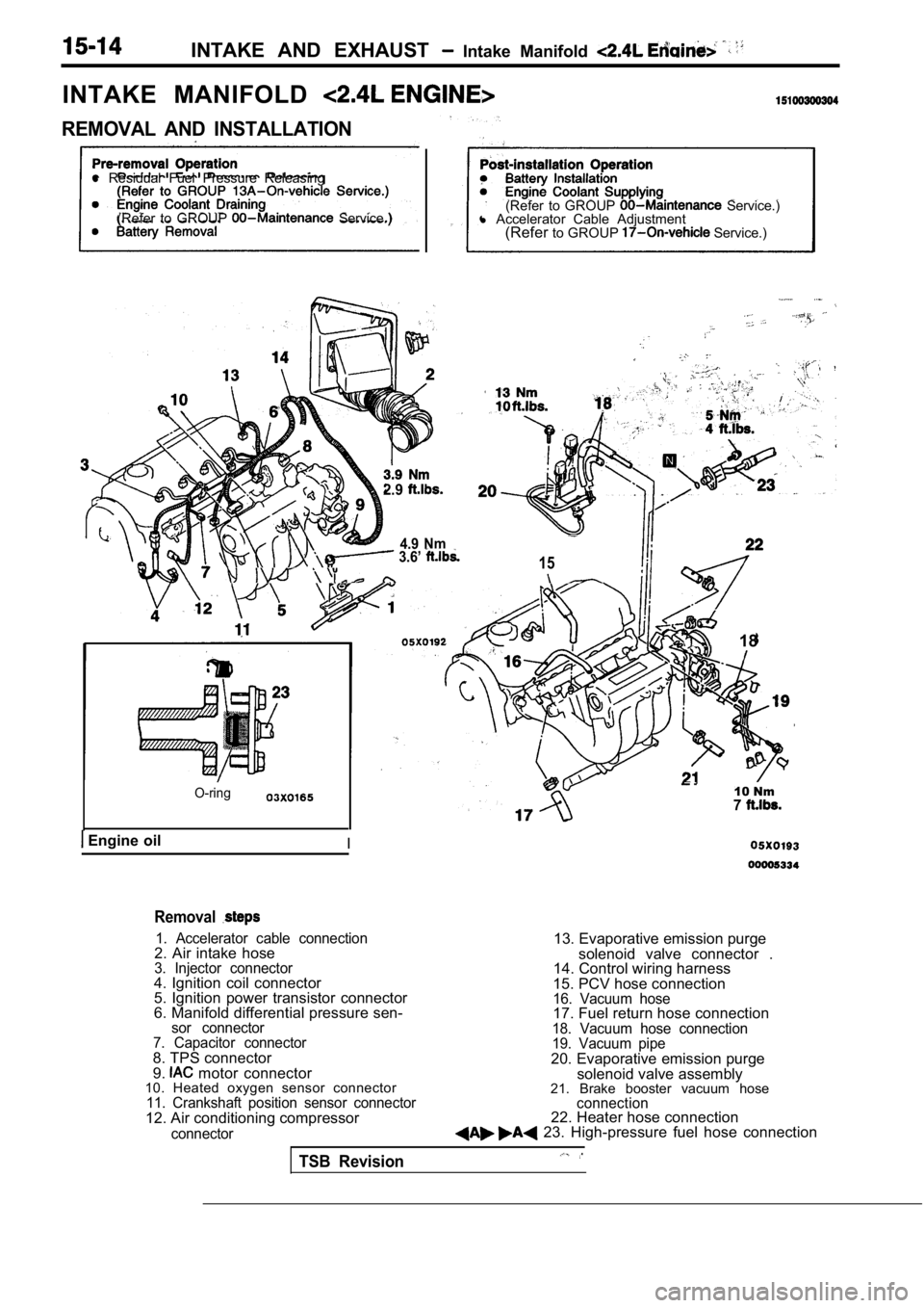
INTAKE AND EXHAUST Intake Manifold
INTAKE MANIFOLD
REMOVAL AND INSTALLATION
l Residual Fuel Pressure Releasing
(Refer to GROUP
Service.) (Refer to GROUP Service.)
l Accelerator Cable Adjustment
(Refer to GROUP
Service.)
2.9
4.9 Nm 3.6’ 15
O-ring
Engine oilI
18
10 Nm7
Removal
1. Accelerator cable connection2. Air intake hose3. Injector connector4. Ignition coil connector
5. Ignition power transistor connector
6. Manifold differential pressure sen-
sor connector
7. Capacitor connector
8. TPS connector
9. motor connector
10. Heated oxygen sensor connector
11. Crankshaft position sensor connector12. Air conditioning compressor
connector
13. Evaporative emission purge
solenoid valve connector .
14. Control wiring harness
15. PCV hose connection
16. Vacuum hose17. Fuel return hose connection18. Vacuum hose connection
19. Vacuum pipe
20. Evaporative emission purge solenoid valve assembly
21. Brake booster vacuum hose
connection22. Heater hose connection 23. High-pressure fuel hose connection
TSB Revision
Page 729 of 2103
12 Nm8.7
q 26
3.6
9.8 Nm7.2
3 . 6
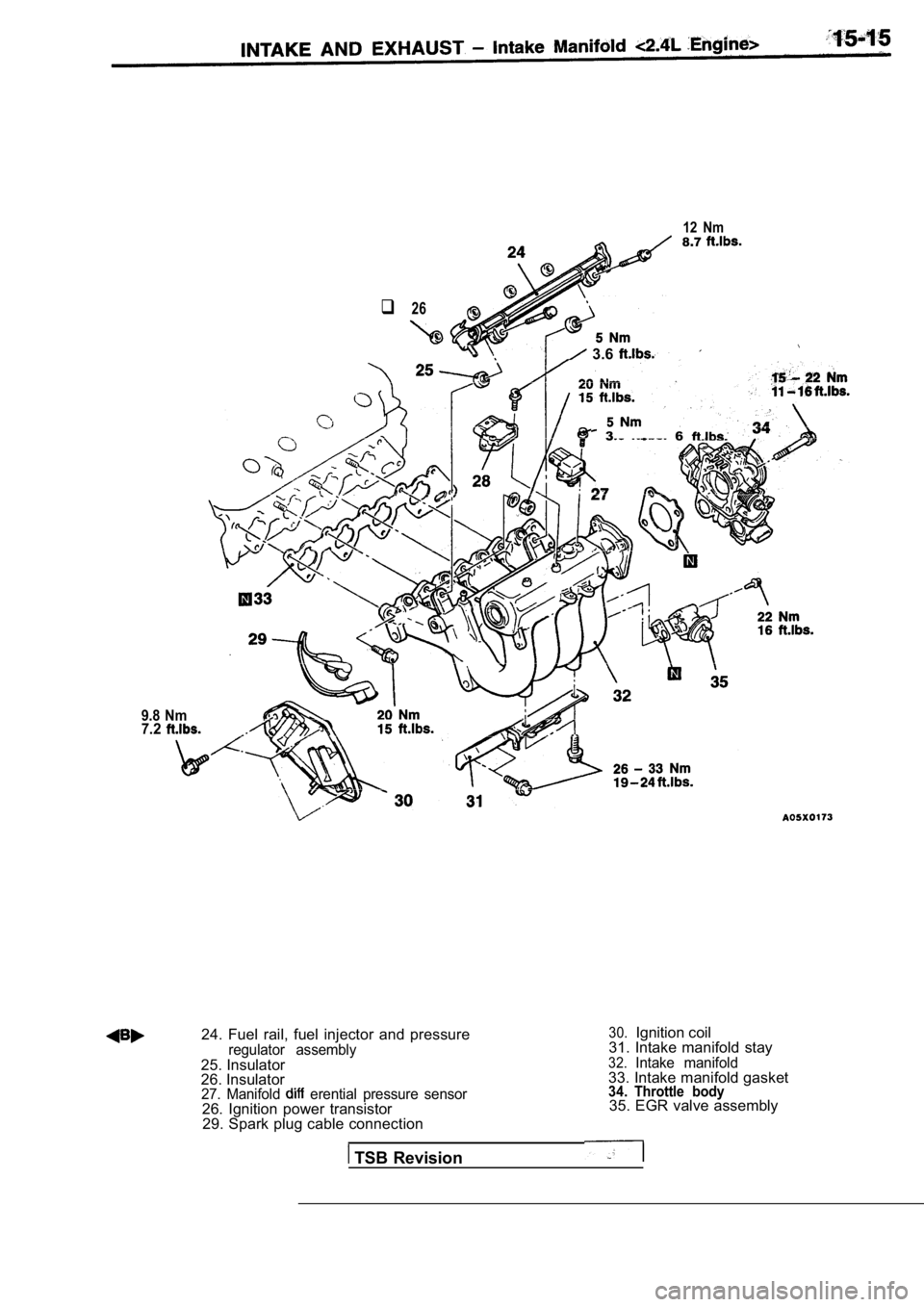
24. Fuel rail, fuel injector and pressureregulator assembly25. Insulator
26. Insulator
27. Manifold erential pressure sensor26. Ignition power transistor29. Spark plug cable connection
TSB Revision
30.Ignition coil
31. Intake manifold stay
32.Intake manifold33. Intake manifold gasket34. Throttle body35. EGR valve assembly
Page 732 of 2103
INTAKE AND EXHAUST Exhaust Manifold
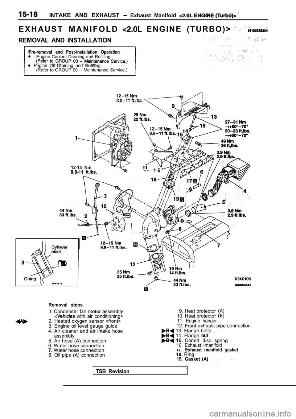
E X H A U S T M A N I F O L D E N G I N E ( T U R B O ) >
REMOVAL AND INSTALLATION
Pre-removal and Post-installation OperationEngine Coolant Draining and Refilling
l Engine Oil Draining and Refilling
(Refer to GROUP 00
Maintenance Service.)
Nm
12-15 Nm8.8-11- - 1 6 ’
3
. .
Removal steps
1. Condenser fan motor assembly with air conditioning>
2. Heated oxygen sensor
3. Engine oil level gauge guide
4. Air cleaner and air intake hose
assembly5. Air hose (A) connection
6. Water hose connection
7. Water hose connection
8. Oil pipe (A) connection 9. Heat protector
A)
10. Heat protectorB)
11. Engine hanger
12. Front exhaust pipe connection 13. Flange bolts 14. Flange 15.
Coned disc spring .16. Exhaust -manifold17.Exhaust manifold gasket Ring19. Gasket (A)
TSB Revision
Page 733 of 2103
INTAKE AND EXHAUST Exhaust Manifold
24 ,
54-64 Nm
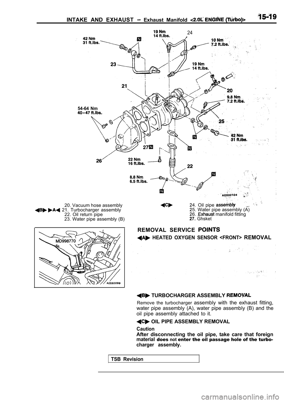
20. Vacuum hose assembly 21. Turbocharger assembly22. Oil return pipe
23. Water pipe assembly (B) 24. Oil pipe 25. Water pipe assembly (A)
26. manifold fitting27.Ghsket
REMOVAL SERVICE
HEATED OXYGEN SENSOR
TSB Revision
TURBOCHARGER ASSEMBLY
Remove the turbocharger
assembly with the exhaust fitting,
water pipe assembly (A), water pipe assembly (B) an d the
oil pipe assembly attached to it.
OIL PIPE ASSEMBLY REMOVAL
Caution
After disconnecting the oil pipe, take care that fo reign
materialdoesnotenter the oil passage hole of the turbo-
charger assembly.
Page 736 of 2103
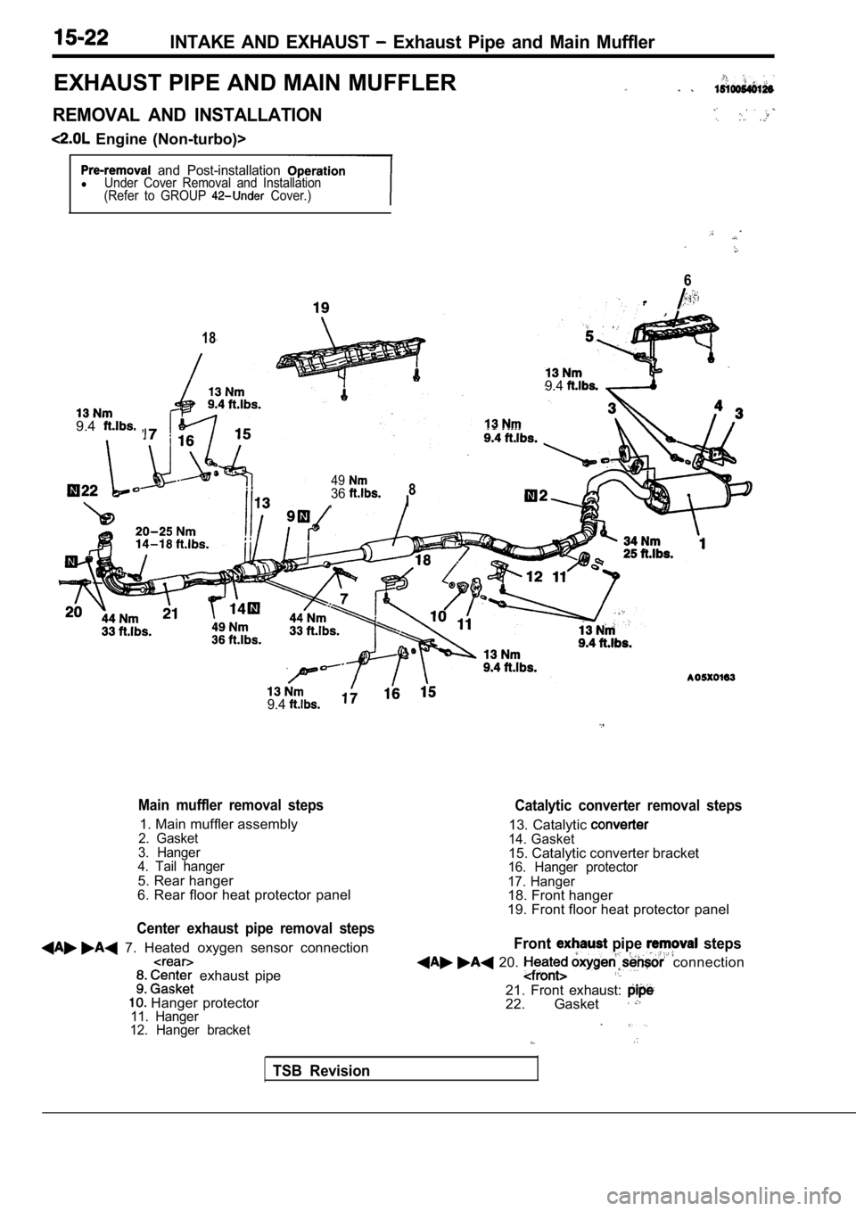
INTAKE AND EXHAUST Exhaust Pipe and Main Muffler
EXHAUST PIPE AND MAIN MUFFLER
REMOVAL AND INSTALLATION
Engine (Non-turbo)>
and Post-installationlUnder Cover Removal and Installation
(Refer to GROUP Cover.)
18
9.4 ,
4936,8I
6
9.4
9.4
Main muffler removal steps Catalytic converter removal steps
1. Main muffler assembly2. Gasket13. Catalytic 14. Gasket
3. Hanger
4. Tail hanger15. Catalytic converter bracket
5. Rear hanger16. Hanger protector
6. Rear floor heat protector panel17. Hanger18. Front hanger
Center exhaust pipe removal steps
7. Heated oxygen sensor connection
exhaust pipe
Hanger protector11. Hanger
12. Hanger bracket
TSB Revision
19. Front floor heat protector panel
Front pipe steps
20. connection
21. Front exhaust:22. Gasket
Page 737 of 2103
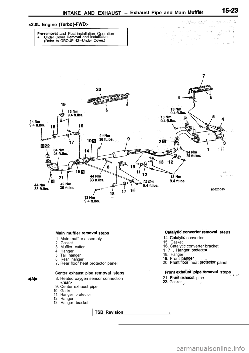
INTAKE AND EXHAUST Exhaust Pipe and Main
Engine
and Post-installation Operation
139.4
49
6
25
1
443336
33
9.4
16
9.4
--9.4
Main muffler steps
1. Main muffler assembly
2.Gasket3.Muffler cutter
4.Hanger5.Tail hanger6.Rear hanger7. Rear floor heat protector panel
Center exhaust pipe removal steps
8. Heated oxygen sensor connection
9. Center exhaust pipe10.Gasket11.Hanger protector12.Hanger13.Hanger bracket
steps
14.
converter
15. Gasket16. Catalytic converter bracket
1 7 .
18. Hanger Front .20: ‘heat panel
steps
21.
pipe22.Gasket
TSB Revision,
Page 738 of 2103
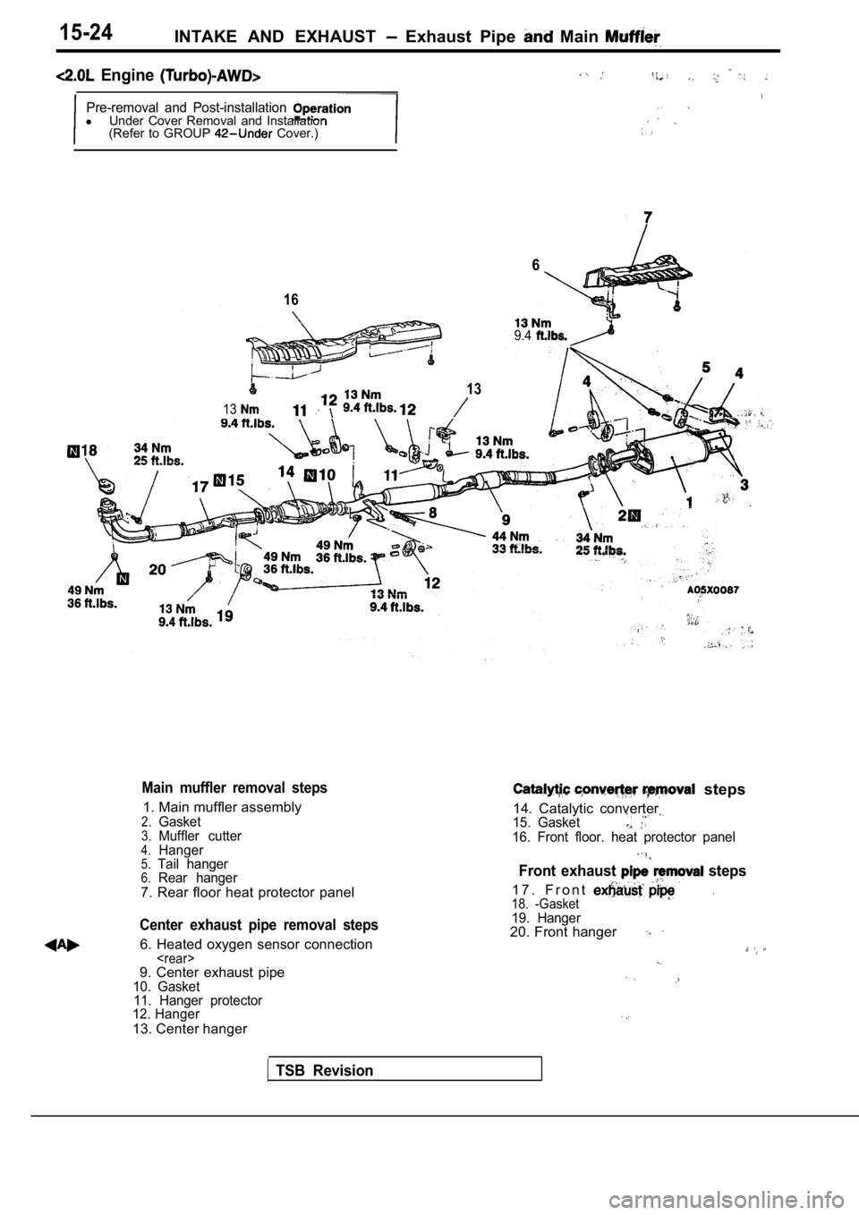
15-24INTAKE AND EXHAUST Exhaust Pipe Main
Engine
Pre-removal and Post-installationlUnder Cover Removal and Installation
(Refer to GROUP Cover.)
16
13
13
6
9.4
Main muffler removal steps
1. Main muffler assembly
2.Gasket3.Muffler cutter4.Hanger5.Tail hanger6.Rear hanger
7. Rear floor heat protector panel
Center exhaust pipe removal steps
6. Heated oxygen sensor connection
11. Hanger protector
12. Hanger
13. Center hanger
steps
14. Catalytic converter
15. Gasket
16. Front floor. heat protector panel
Front exhaust steps
1 7 . F r o n t .18. -Gasket19. Hanger20. Front hanger
TSB Revision
Page 739 of 2103
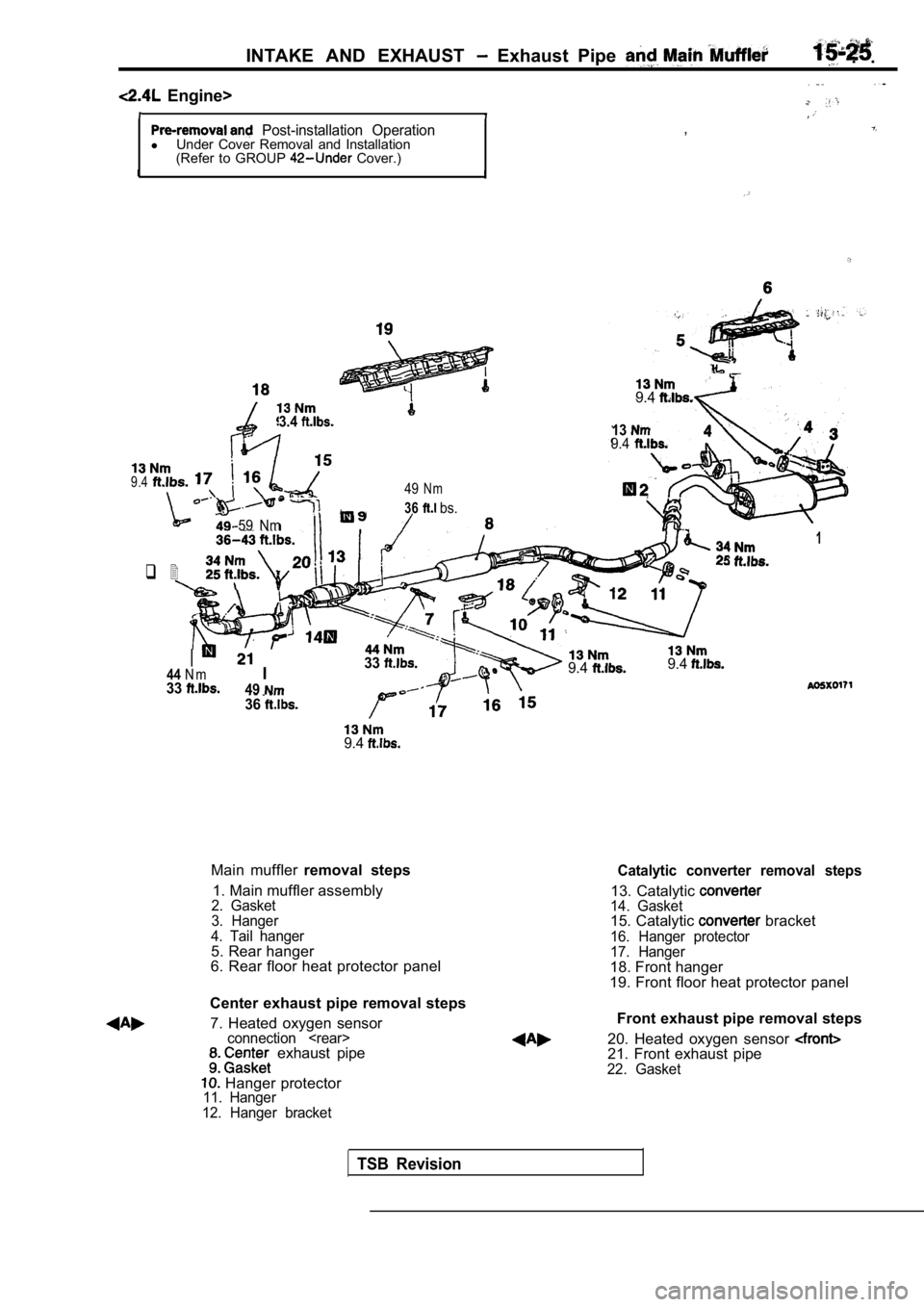
INTAKE AND EXHAUST Exhaust Pipe . .
Engine>
Post-installation OperationlUnder Cover Removal and Installation
(Refer to GROUP Cover.) ,
3.4
9.4
139.4
9.449N m
36 bs.
-59 Nm
q 2
9.4
Main muffler
removal steps
1. Main muffler assembly
2. Gasket
3. Hanger
4. Tail hanger
5. Rear hanger
6. Rear floor heat protector panel
Center exhaust pipe removal steps 7. Heated oxygen sensor
connection
Hanger protector11. Hanger
12. Hanger bracket
9.49.4
1
Catalytic converter removal steps
13. Catalytic 14. Gasket15. Catalytic bracket
16. Hanger protector
17. Hanger
18. Front hanger
19. Front floor heat protector panel
II3344N m334936
Front exhaust pipe removal steps
20. Heated oxygen sensor
21. Front exhaust pipe22. Gasket
TSB Revision
Page 740 of 2103
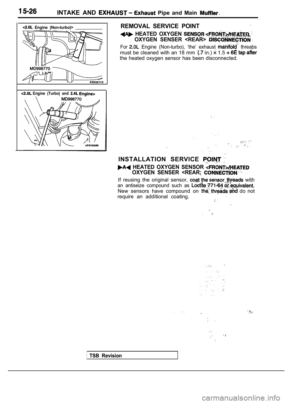
INTAKE AND Pipe and Main
Engine (Non-turbo)>
Engine (Turbo) and
REMOVAL SERVICE POINT
HEATED OXYGEN
OXYGEN SENSER
For Engine (Non-turbo), ‘the’ exhaust threabs
must be cleaned with an 18 mm in.) 1.5
the heated oxygen sensor has been disconnected.
INSTALLATION SERVICE
HEATED OXYGEN SENSOR
OXYGEN SENSER
an antiseize compound such as
New sensors have compound on do not
require an additional coating.
TSB Revision
TSB Revision
Page 741 of 2103
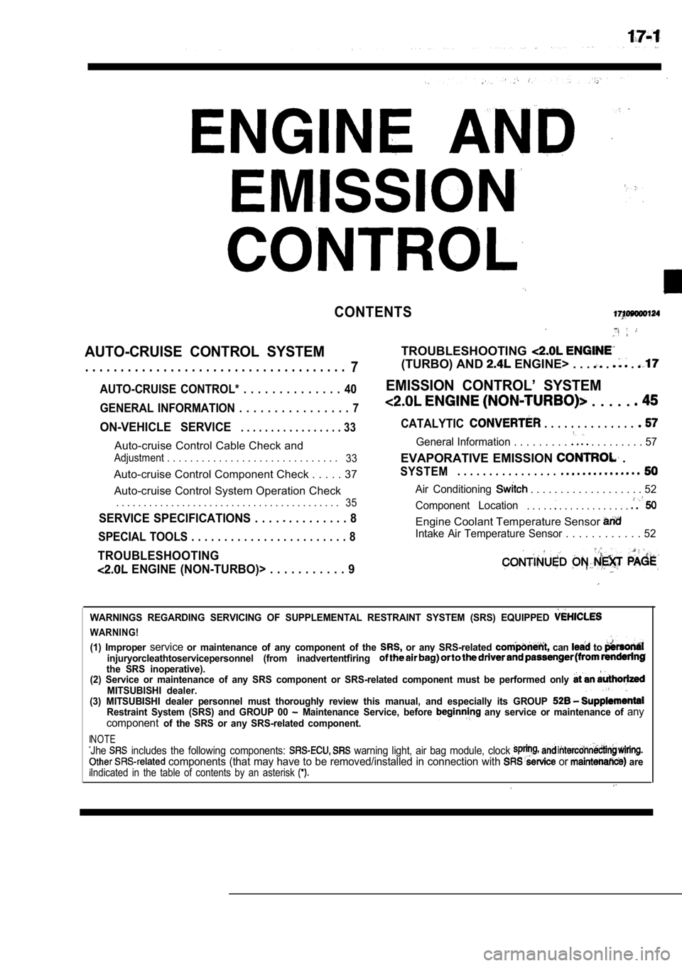
CONTENTS
AUTO-CRUISE CONTROL SYSTEM
. . . . . . . . . . . . . . . . . . . . . . . . . . . . . . . . . . . . .7
AUTO-CRUISE CONTROL* . . . . . . . . . . . . . . 40
GENERAL INFORMATION . . . . . . . . . . . . . . . . 7
ON-VEHICLE SERVICE. . . . . . . . . . . . . . . . . 33
Auto-cruise Control Cable Check and
Adjustment . . . . . . . . . . . . . . . . . . . . . . . . . . . . . .
33
Auto-cruise Control Component Check . . . . . 37
Auto-cruise Control System Operation Check
. . . . . . . . . . . . . . . . . . . . . . . . . . . . . . . . . . . . . . . . .
35
SERVICE SPECIFICATIONS . . . . . . . . . . . . . 8
SPECIAL TOOLS . . . . . . . . . . . . . . . . . . . . . . . . 8
TROUBLESHOOTING
ENGINE (NON-TURBO)> . . . . . . . . . . . 9
TROUBLESHOOTING
(TURBO) AND ENGINE> . . . . .
EMISSION CONTROL’ SYSTEM
. . . . .
CATALYTIC . . . . . . . . . . . . . .
General Information . . . . . . . . . . . . . . . . . . 57
EVAPORATIVE EMISSION .
SYSTEM. . . . . . . . . . . . . . . .
Air Conditioning . . . . . . . . . . . . . . . . . . . 52
Component Location
. . . . . . . . . . . . . . . . . .
Engine Coolant Temperature Sensor
Intake Air Temperature Sensor . . . . . . . . . . . . 52
WARNINGS REGARDING SERVICING OF SUPPLEMENTAL RESTRA INT SYSTEM (SRS) EQUIPPED
WARNING!
(1) Improper serviceor maintenance of any component of the or any SRS-related can to injuryorcleathtoservicepersonnel (from inadvertentfiring the SRS inoperative).
(2) Service or maintenance of any SRS component or SRS-related component must be performed only
MITSUBISHI dealer.
(3) MITSUBISHI dealer personnel must thoroughly rev iew this manual, and especially its GROUP
Restraint System (SRS) and GROUP 00 Maintenance Service, before any service or maintenance of any
componentof the SRS or any SRS-related component.
NOTEJhe includes the following components: warning light, air bag module, clock components (that may have to be removed/installed in connection with or areIndicated in the table of contents by an asterisk