clock MITSUBISHI SPYDER 1990 Service Repair Manual
[x] Cancel search | Manufacturer: MITSUBISHI, Model Year: 1990, Model line: SPYDER, Model: MITSUBISHI SPYDER 1990Pages: 2103, PDF Size: 68.98 MB
Page 22 of 2103
GENERAL before Service
PRECAUTIONS BEFORE SERVICE.
SUPPLEMENTAL RESTRAINT SYSTEM
1. to follow when servicing SRS
(1) Be sure to read GROUP Supplemental Restraint System
For safe operations, please follow the directions a nd heed all
(2) Always use the designated special tools and tes t equipment.
(3) Wait at least 60 seconds after disconnecting the battery cable before” further work;
The SRS system is designed to retain enough voltage to deploy the air bag even after the battery
has been disconnected. Serious injury may result from unintended air bag deployment if work
is done on the SRS system immediately after the bat tery cable is disconnected.
(4) Never attempt to disassemble or repair the SRS components (SRS-ECU air bag module and
clock spring). If faulty, replace it.
(5) Warning labels must be heeded when servicing or handling SRS components. Warning labels
are located in the following locations.
Sun visor
l Glove box
. S R S - E C U
l Steering wheel
l Air bag module
l Clock spring
l Steering gear and linkage clamp
(6) Store components removed from the SRS
a clean and dry place.
The air bag module should be stored on a flat surfa ce and placed so that the pad surface is’
facing upward.
Do not place anything on top of it.
(7) Be sure to deploy the air bag before disposing of the air bag’module or disposing of a vehicle
equipped with an air bag. (Refer to GROUP
Air Bag Module Disposal Procedures.)
(8) Whenever you finish servicing the
check the SRS warning light operation to make sure
that the system functions properly.
2.Observe the following when carrying out operations on places where SRS components are installed,’
.,
including operations not directly related to the SR S air bag.
(1) When removing or installing parts do not allow any impact or shock to the SRS components.
(2) SRS components should not be subjected to heat over so remove the SRS compo-
nents before drying or baking the vehicle after painting.
After re-installing them, check the SRS warning lig ht operation to make sure that the system
functions properly.
SERVICING THE ELECTRICAL SYSTEM
1. Note the following before proceeding with work o n the
electrical system.
Note that the following must never be done:
Unauthorized modifications of any electrical device or
wiring, because such modifications might lead to a vehicle
malfunction, over-capacity or short-circuit that co uld result
in a fire in the vehicle.
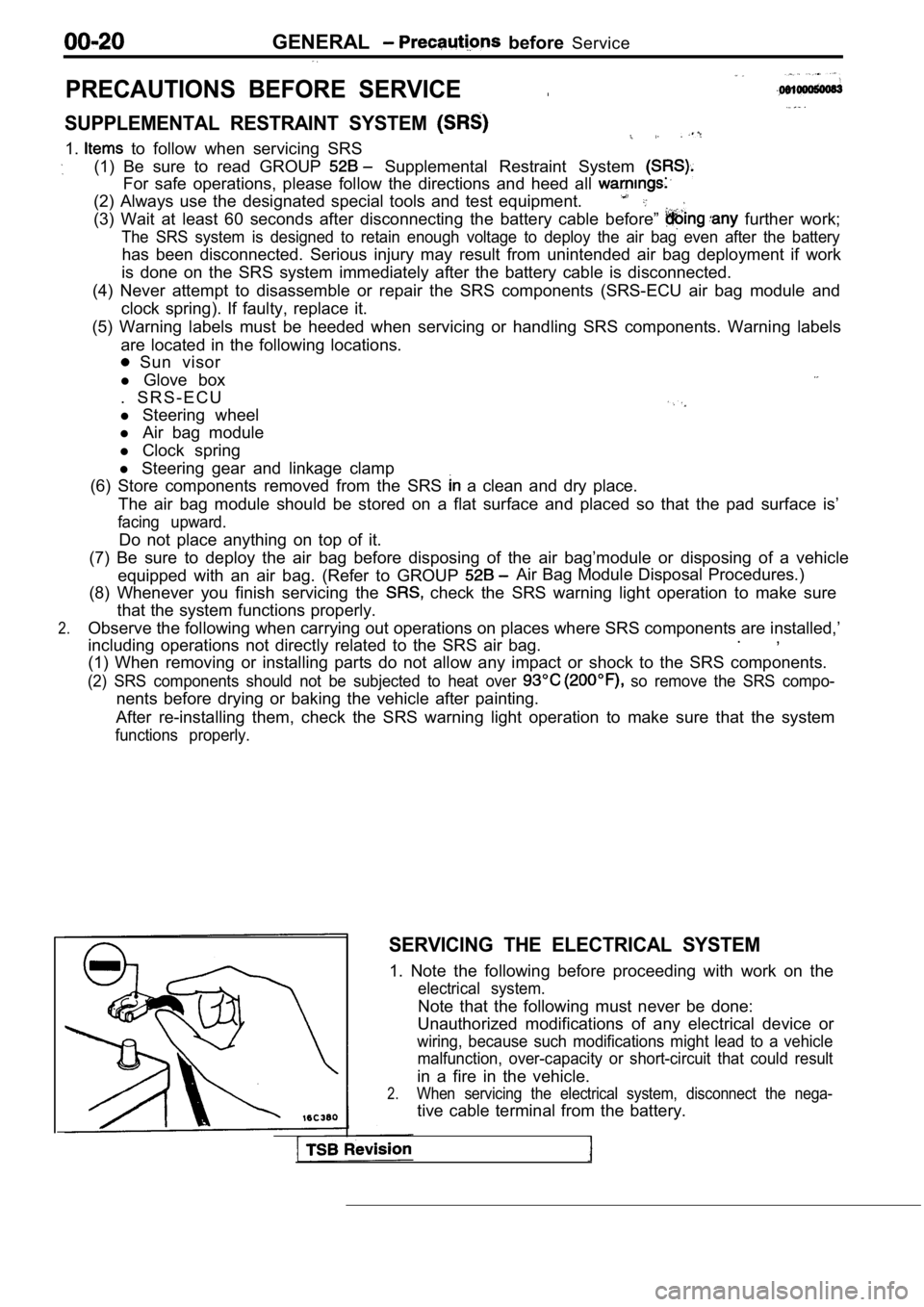
2.When servicing the electrical system, disconnect th e nega-
tive cable terminal from the battery.
Page 54 of 2103
GENERAL Maintenance Service
0 0 0 0 0 1 6 7
Inflator case
CHECK
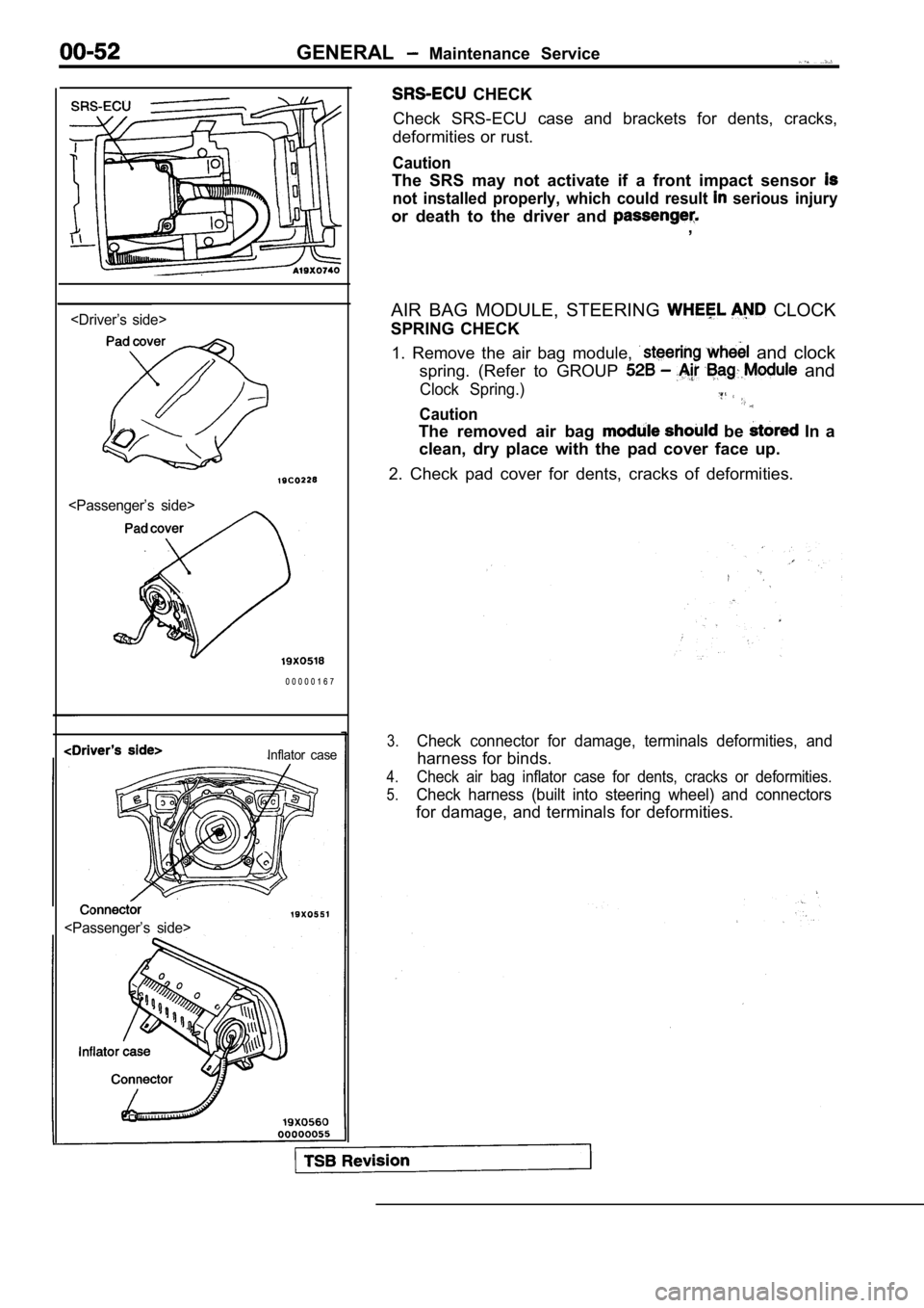
Check SRS-ECU case and brackets for dents, cracks,
deformities or rust.
Caution
The SRS may not activate if a front impact sensor
not installed properly, which could result serious injury
or death to the driver and ,
AIR BAG MODULE, STEERING
CLOCK
SPRING CHECK
1. Remove the air bag module,
and clock
spring. (Refer to GROUP
and
Clock Spring.)
Caution
The removed air bag be In a
clean, dry place with the pad cover face up.
2. Check pad cover for dents, cracks of deformities .
3.Check connector for damage, terminals deformities, and
harness for binds.
4.Check air bag inflator case for dents, cracks or deformities.
5.Check harness (built into steering wheel) and conne ctors
for damage, and terminals for deformities.
Page 55 of 2103
G E N E R A L Maintenance
Protective tube
harness
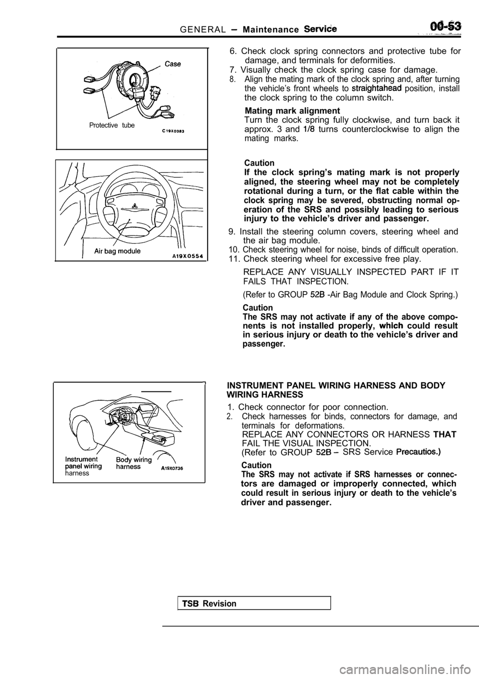
6. Check clock spring connectors and protective tube for
damage, and terminals for deformities.
7. Visually check the clock spring case for damage.
8.Align the mating mark of the clock spring and, afte r turning
the vehicle’s front wheels to
position, install
the clock spring to the column switch.
Mating mark alignment
Turn the clock spring fully clockwise, and turn bac k it
approx. 3 and
turns counterclockwise to align the
mating marks.
Caution
If the clock spring’s mating mark is not properly
aligned, the steering wheel may not be completely
rotational during a turn, or the flat cable within the
clock spring may be severed, obstructing normal op-
eration of the SRS and possibly leading to serious
injury to the vehicle’s driver and passenger.
9. Install the steering column covers, steering whe el and
the air bag module.
10. Check steering wheel for noise, binds of diffic ult operation.
11. Check steering wheel for excessive free play.
REPLACE ANY VISUALLY INSPECTED PART IF IT
FAILS THAT INSPECTION.
(Refer to GROUP
-Air Bag Module and Clock Spring.)
Caution
The SRS may not activate if any of the above compo-
nents is not installed properly, could result
in serious injury or death to the vehicle’s driver and
passenger.
INSTRUMENT PANEL WIRING HARNESS AND BODY
WIRING HARNESS
1. Check connector for poor connection.
2.Check harnesses for binds, connectors for damage, a nd
terminals for deformations.
REPLACE ANY CONNECTORS OR HARNESS THAT
FAIL THE VISUAL INSPECTION.
(Refer to GROUP
SRS Service
Caution
The SRS may not activate if SRS harnesses or connec -
tors are damaged or improperly connected, which
could result in serious injury or death to the vehicle’s
driver and passenger.
Revision
Page 100 of 2103
E N G I N E Belt
Auto tensioner
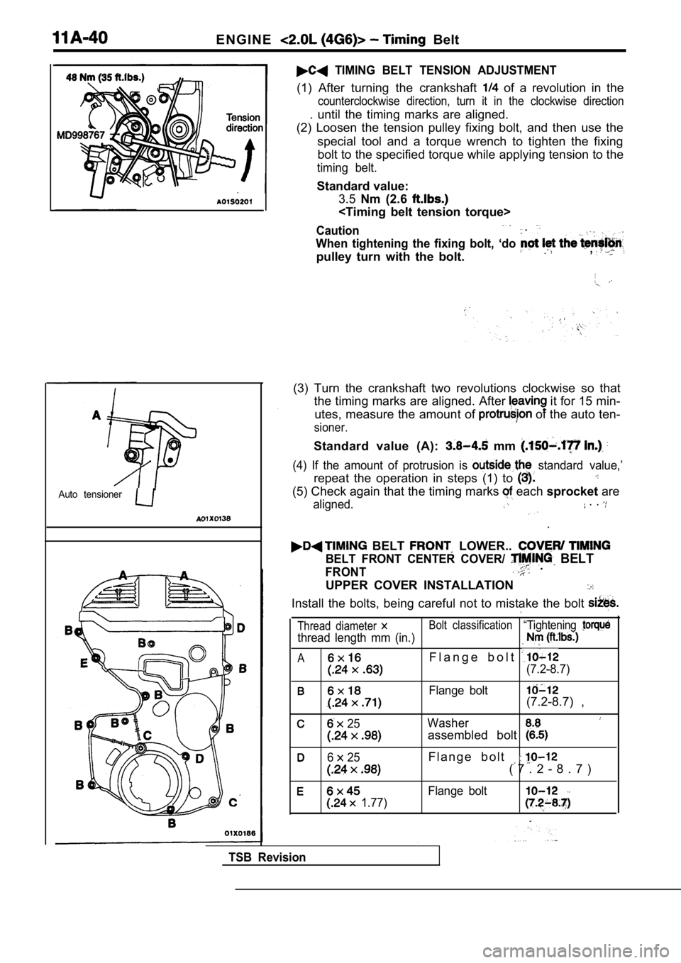
TIMING BELT TENSION ADJUSTMENT
(1) After turning the crankshaft of a revolution in the
counterclockwise direction, turn it in the clockwise direction
. until the timing marks are aligned.
(2) Loosen the tension pulley fixing bolt, and then use the
special tool and a torque wrench to tighten the fix ing
bolt to the specified torque while applying tension to the
timing belt.
Standard value:
3.5 Nm (2.6
Caution
When tightening the fixing bolt, ‘do
pulley turn with the bolt.,
(3) Turn the crankshaft two revolutions clockwise s o that
the timing marks are aligned. After
it for 15 min-
utes, measure the amount of
of the auto ten-
sioner.
Standard value (A): mm
(4) If the amount of protrusion is standard value,’
repeat the operation in steps (1) to
(5) Check again that the timing marks each sprocket are
aligned. . .
.
BELT LOWER..
BELT FRONT CENTER COVER/ BELT
FRONT .
UPPER COVER INSTALLATION
Install the bolts, being careful not to mistake the bolt
Thread diameter Bolt classification“Tightening
thread length mm (in.)
AF l a n g e b o l t
(7.2-8.7)
Flange bolt(7.2-8.7) ,
25Washer
assembled bolt
6 25F l a n g e b o l t
( 7 . 2 - 8 . 7 )
Flange bolt
1.77)
TSB Revision
Page 124 of 2103
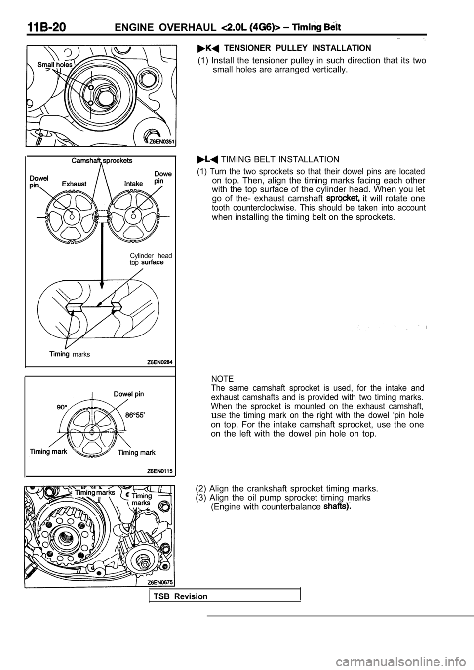
ENGINE OVERHAUL
TENSIONER PULLEY INSTALLATION
(1) Install the tensioner pulley in such direction that its two
small holes are arranged vertically.
Cylinder head
top
marks
TIMING BELT INSTALLATION
(1) Turn the two sprockets so that their dowel pins are located
on top. Then, align the timing marks facing each ot her
with the top surface of the cylinder head. When you let
go of the- exhaust camshaft
it will rotate one
tooth counterclockwise. This should be taken into a ccount
when installing the timing belt on the sprockets.
NOTE
The same camshaft sprocket is used, for the intake and
exhaust camshafts and is provided with two timing m arks.
When the sprocket is mounted on the exhaust camshaf t,
usethe timing mark on the right with the dowel ‘pin hole
on top. For the intake camshaft sprocket, use the o ne
on the left with the dowel pin hole on top.
(2) Align the crankshaft sprocket timing marks.
(3) Align the oil pump sprocket timing marks (Engine with counterbalance
TSB Revision
Page 126 of 2103
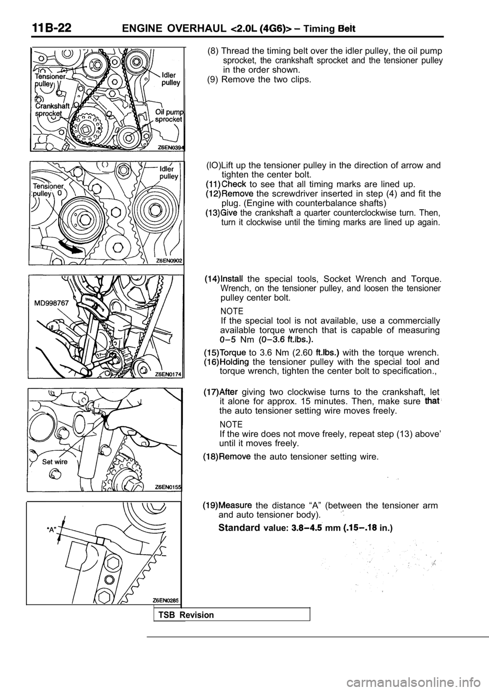
ENGINE OVERHAUL Timing
(8) Thread the timing belt over the idler pulley, the oil pump
sprocket, the crankshaft sprocket and the tensioner pulley
in the order shown.
(9) Remove the two clips.
(lO)Lift up the tensioner pulley in the direction o f arrow and
tighten the center bolt.
to see that all timing marks are lined up.
the screwdriver inserted in step (4) and fit the
plug. (Engine with counterbalance shafts)
the crankshaft a quarter counterclockwise turn. Th en,
turn it clockwise until the timing marks are lined up again.
the special tools, Socket Wrench and Torque.
Wrench, on the tensioner pulley, and loosen the ten sioner
pulley center bolt.
NOTE
If the special tool is not available, use a commercially
available torque wrench that is capable of measurin g
Nm
to 3.6 Nm (2.60 with the torque wrench.
the tensioner pulley with the special tool and
torque wrench, tighten the center bolt to specifica tion.,
giving two clockwise turns to the crankshaft, let
it alone for approx. 15 minutes. Then, make sure
the auto tensioner setting wire moves freely.
NOTE
If the wire does not move freely, repeat step (13) above’
until it moves freely.
the auto tensioner setting wire.
the distance “A” (between the tensioner arm
and auto tensioner body).
Standard value: mm in.)
TSB Revision
Page 179 of 2103
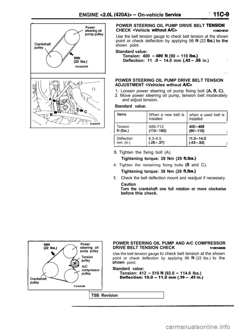
ENGINE On-vehicle
Power
Powersteering oilpump pulleyTension
pulley
POWER STEERING OIL PUMP DRIVE BELT
CHECK
point or check deflection by applying 98 (22 to the
shown point.
Standard value:
Tension: 400
(90 110
Deflection: 11 14.0 mm in.)
POWER STEERING OIL PUMP DRIVE BELT TENSION
ADJUSTMENT
2. Move power steering oil pump, tension belt moder ately
and adjust tension.
Standard value:
When a new belt is when a used belt is
installedinstalled
Tension489-712
I
Deflection6.5-9.5
mm (in.)I
Tighten the fixing bolt (A).
Tightening torque: 39 Nm (29
4. Tighten the remaining fixing bolts and C).
Tightening torque: 39 Nm (29
5.Check the belt deflection mount and readjust if nec essary.
Caution
Turn the crankshaft one full rotation or more clock wise
before this check.
POWER STEERING OIL PUMP AND A/C COMPRESSOR
DRIVE BELT TENSION CHECK
Use the belt tension gauge to check belt tension at the shown
point or check deflection by applying 98
(22 Ibs.) to the
point.
Standard value:
Tension: 412 510 (92.6 114.6 Ibs.)
Deflection: 10.0
11.0 mm in.)
TSB Revision
Page 282 of 2103
ENGINE On-vehicle
NOTE
lIf the vehicle is parked on a slope for long, oil
in the lash adjusters will
and ‘air may
enter the high-pressure’ chamber when the vehicle
i s s t a r t e d .
lAfter the vehicle is parked for long, air may enter the high-pressure
because, the oil in the
oil passage will be gone it take a time before
the oil is supplied to the
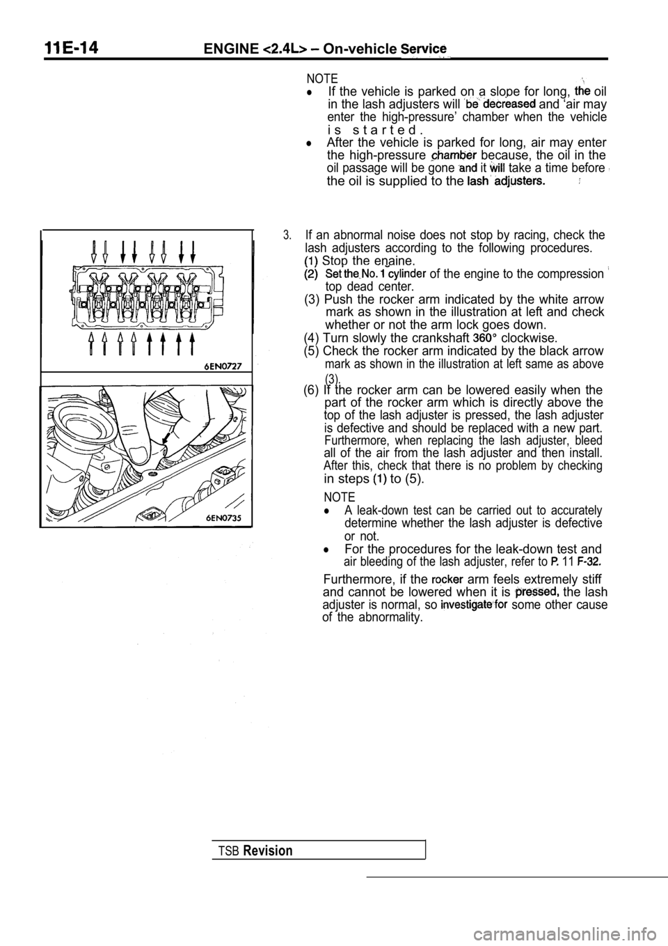
3.If an abnormal noise does not stop by racing, check the
lash adjusters according to the following procedure s.
Stop the enaine.
of the engine to the compression
top dead center.
(3) Push the rocker arm indicated by the white arrow
mark as shown in the illustration at left and check
whether or not the arm lock goes down.
(4) Turn slowly the crankshaft
clockwise.
(5) Check the rocker arm indicated by the black arr ow
mark as shown in the illustration at left same as above
(3).(6) If the rocker arm can be lowered easily when th e
part of the rocker arm which is directly above the
top of the lash adjuster is pressed, the lash adjus ter
is defective and should be replaced with a new part .
Furthermore, when replacing the lash adjuster, blee d
all of the air from the lash adjuster and then install.
After this, check that there is no problem by check ing
in steps to (5).
NOTE
lA leak-down test can be carried out to accurately
determine whether the lash adjuster is defective
or not.
lFor the procedures for the leak-down test and
air bleeding of the lash adjuster, refer to 11
Furthermore, if the arm feels extremely stiff
and cannot be lowered when it is
the lash
adjuster is normal, so some other cause
of the abnormality.
TSBRevision
Page 304 of 2103
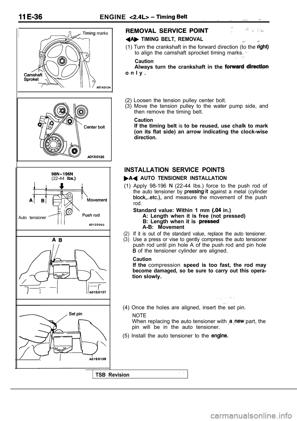
ENGINE
marks
(22-44
Auto tensioner
TIMING BELT, REMOVAL
(1) Turn the crankshaft in the forward direction (to the
to align the camshaft sprocket timing marks.
Caution
Always turn the crankshaft in the
o n l y .
(2) Loosen the tension pulley center bolt.
(3) Move the tension pulley to the water pump side, and
then remove the timing belt.
Caution
If the timing belt isto be reused, use chalk to mark
(on its flat side) an arrow indicating the clock-wi se
direction.
INSTALLATION SERVICE POINTS
AUTO TENSIONER INSTALLATION
(1) Apply 98-196 (22-44 Ibs.) force to the push rod of
the auto tensioner by against a metal (cylinder
and measure the movement of the push
rod.
Standard value: Within 1 mm in.)
A: Length when it is free (not pressed) B: Length when it is
A-B: Movement
(2)If it is out of the standard value, replace the aut o tensioner.
(3)Use a press or vise to gently compress the auto ten sioner
push rod until pin hole A of the push rod and pin hole
of the tensioner cylinder are aligned.
Caution
If the compression speed is too fast, the rod may
become damaged, so be sure to carry out this opera-
tion slowly.
(4) Once the holes are aligned, insert the set pin.
NOTE
When replacing the auto tensioner with part, the
pin will be in the auto tensioner.
(5) Install the auto tensioner to the
TSB Revision
Page 305 of 2103
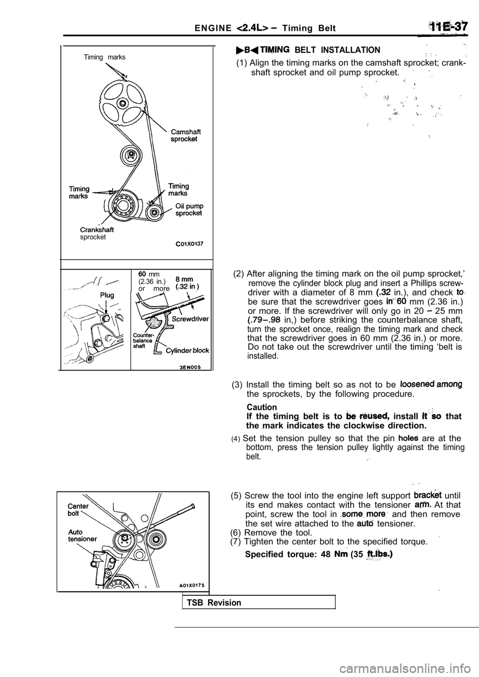
E N G I N E Timing Belt
Timing marks
sprocket
mm
(2.36 in.)
or more .
BELT INSTALLATION
(1) Align the timing marks on the camshaft sprocket ; crank-
shaft sprocket and oil pump sprocket.
,
. . .
(2) After aligning the timing mark on the oil pump sprocket,’
remove the cylinder block plug and insert a Phillips screw-
driver with a diameter of 8 mm in.), and check
be sure that the screwdriver goes mm (2.36 in.)
or more. If the screwdriver will only go in 20
25 mm
in,) before striking the counterbalance shaft,
turn the sprocket once, realign the timing mark and check
that the screwdriver goes in 60 mm (2.36 in.) or mo re.
Do not take out the screwdriver until the timing ‘b elt is
installed.
(3) Install the timing belt so as not to be
the sprockets, by the following procedure.
Caution
If the timing belt is to install that
the mark indicates the clockwise direction.
(4) Set the tension pulley so that the pin
are at the
bottom, press the tension pulley lightly against th e timing
belt.
TSB Revision
(5) Screw the tool into the engine left support until
its end makes contact with the tensioner
At that
point, screw the tool in
and then remove
the set wire attached to the
tensioner.
(6) Remove the tool.
(7) Tighten the center bolt to the specified torque .
Specified torque: 48 (35