height MITSUBISHI SPYDER 1990 Service Owner's Manual
[x] Cancel search | Manufacturer: MITSUBISHI, Model Year: 1990, Model line: SPYDER, Model: MITSUBISHI SPYDER 1990Pages: 2103, PDF Size: 68.98 MB
Page 638 of 2103
Analyzer
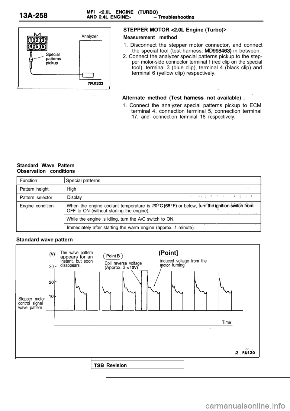
STEPPER MOTOR Engine (Turbo)>
Measurement method
1. Disconnect the stepper motor connector, and connect
the special tool (test harness:
in between.
2. Connect the analyzer special patterns pickup to the step-
per motor-side connector terminal (red clip on the special
tool), terminal 3 (blue clip), terminal 4 (black clip) and
terminal 6 (yellow clip) respectively.
Alternate method (Test
not available) .
1. Connect the analyzer special patterns pickup to ECM
terminal 4, connection terminal 5, connection termi nal
17, and’ connection terminal 18 respectively.
Standard Wave Pattern
Observation conditions
Function Special patterns
Pattern height
Pattern selector
Engine conditionHigh
Display
When the engine coolant temperature is or below,
OFF to ON (without starting the engine)..
While the engine is idling, turn the A/C switch to ON.. .Immediately after starting the warm engine (approx. 1 minute).
Standard wave pattern
The wave patternappears for aninstant, but soon
30disappears.
Stepper motor
10
control signal
wave pattern
Coil reverse voltage(Approx. 3
(Point]
induced voltage from the turning
Time
Revision
Page 639 of 2103
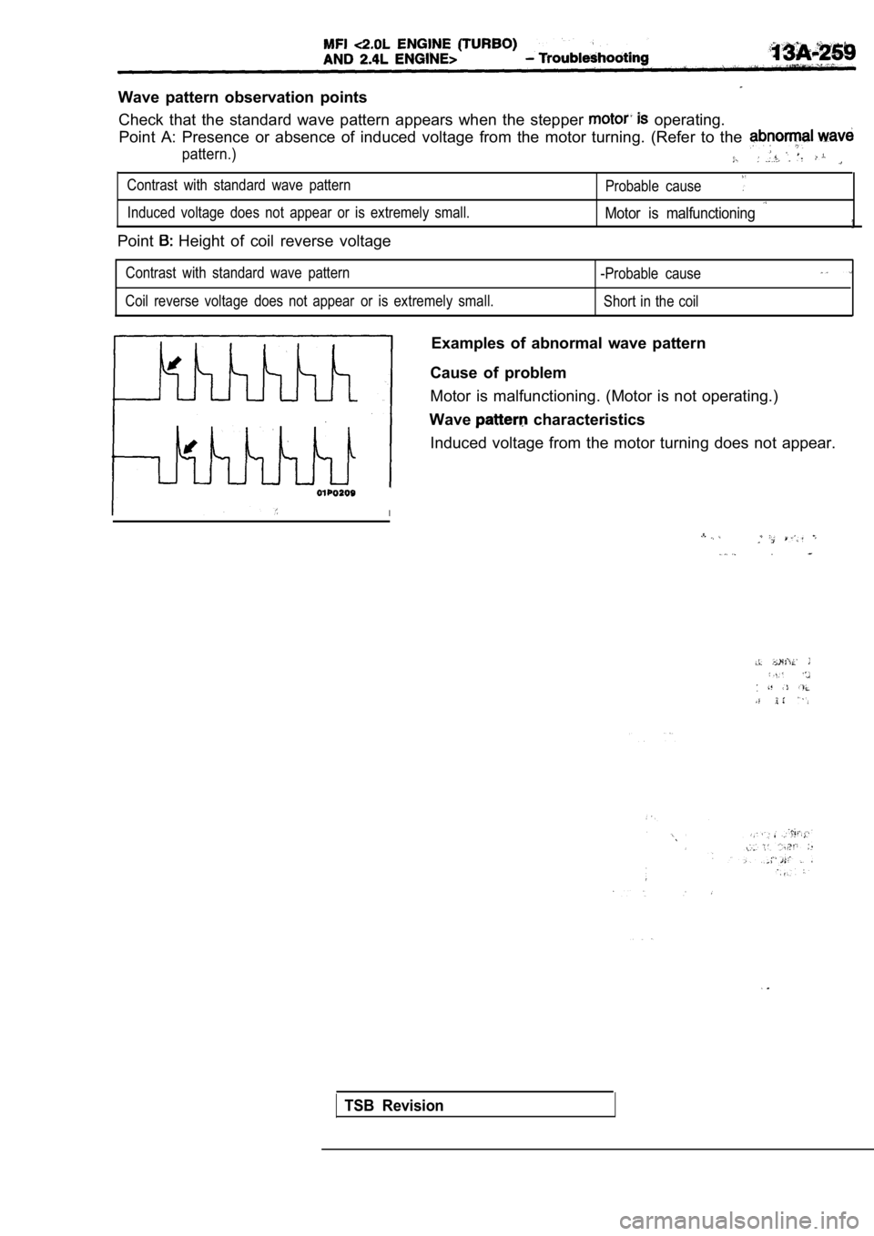
Wave pattern observation pointsCheck that the standard wave pattern appears when t he stepper
operating.
Point A: Presence or absence of induced voltage fro m the motor turning. (Refer to the
pattern.)
Contrast with standard wave pattern
Probable cause
Induced voltage does not appear or is extremely small.Motor is malfunctioning
Point Height of coil reverse voltage
Contrast with standard wave pattern
-Probable cause
Coil reverse voltage does not appear or is extremely small.
Short in the coil
Examples of abnormal wave pattern
Cause of problem
Motor is malfunctioning. (Motor is not operating.)
Wave
characteristics
Induced voltage from the motor turning does not app ear.
I
.
TSB Revision
Page 640 of 2103
ENGINE (TURBO)
AND ENGINE>
Analyzer
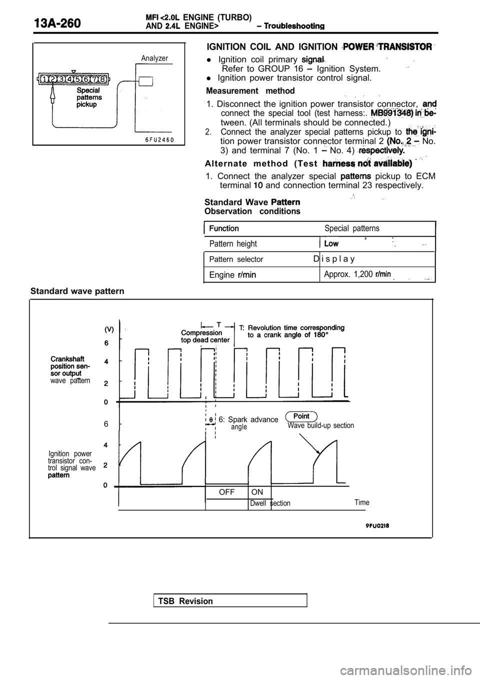
IGNITION COIL AND IGNITION
l Ignition coil primary
Refer to GROUP 16 Ignition System.
l Ignition power transistor control signal.
Measurement method
1. Disconnect the ignition power transistor connect or,
connect the special tool (test harness:.
tween. (All terminals should be connected.)
2.Connect the analyzer special patterns pickup to
tion power transistor connector terminal 2 No.
3) and terminal 7 (No. 1
No. 4)
A l t e r n a t e m e t h o d ( T e s t
1. Connect the analyzer special pickup to ECM
terminal
and connection terminal 23 respectively.
Standard Wave
Observation conditions
Special patterns
Pattern height
Pattern selector
Engine
D i s p l a y
Approx. 1,200
Standard wave pattern
TSB Revision
wave pattern
6 6: Spark advanceangleWave build-up section
Ignition power
transistor con-
trol signal wave
OFF ON
Dwell section Time
Page 705 of 2103
E N G I N E C O O L I N G T h e r m o s t a t ” .
Engine (Non-turbo)>
Engine (Turbo) and Engine>
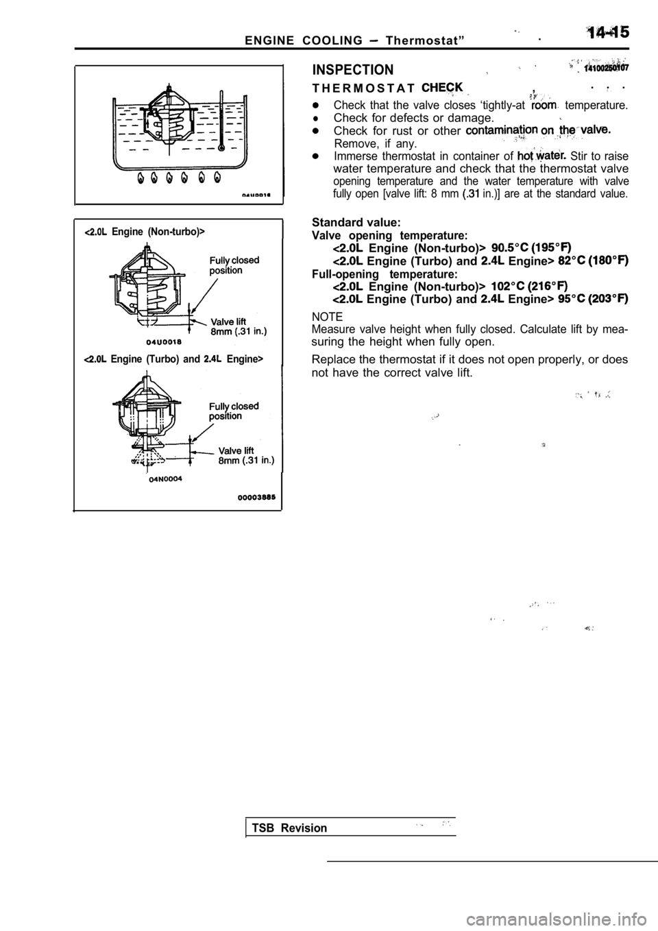
INSPECTION
T H E R M O S T A T. . .
,
Check that the valve closes ‘tightly-at temperature.
lCheck for defects or damage.
Check for rust or other
Remove, if any.
Immerse thermostat in container of Stir to raise
water temperature and check that the thermostat val ve
opening temperature and the water temperature with valve
fully open [valve lift: 8 mm
in.)] are at the standard value.
Standard value:
Valve opening temperature:
Engine (Non-turbo)>
Engine (Turbo) and Engine>
Full-opening temperature:
Engine (Non-turbo)>
Engine (Turbo) and Engine>
NOTE
Measure valve height when fully closed. Calculate l ift by mea-
suring the height when fully open.
Replace the thermostat if it does not open properly , or does
not have the correct valve lift.
TSB Revision
Page 833 of 2103
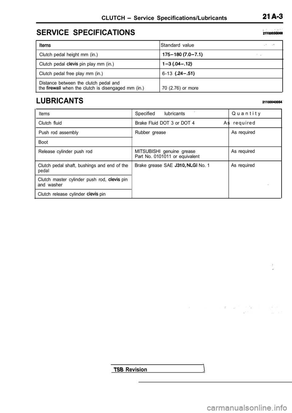
CLUTCH Service Specifications/Lubricants
SERVICE SPECIFICATIONS
Clutch pedal height mm (in.)
Clutch pedal
pin play mm (in.)
Clutch pedal free play mm (in.) Distance between the clutch pedal and
the
when the clutch is disengaged mm (in.)
LUBRICANTS
Standard value
6-13
70 (2.76) or more
Items
Clutch fluid
Push rod assembly
Boot
Specified lubricants
Brake Fluid DOT 3 or DOT 4
Rubber grease
Q u a n t i t y
A s r e q u i r e d
As required
Release cylinder push rod MITSUBISHI genuine grease
Part No. 0101011 or equivalentAs required
Clutch pedal shaft, bushings and end of the Brake grease SAE
No. 1As required
pedal
Clutch master cylinder push rod, pin
and washer
Clutch release cylinder
pin
Revision
Page 835 of 2103
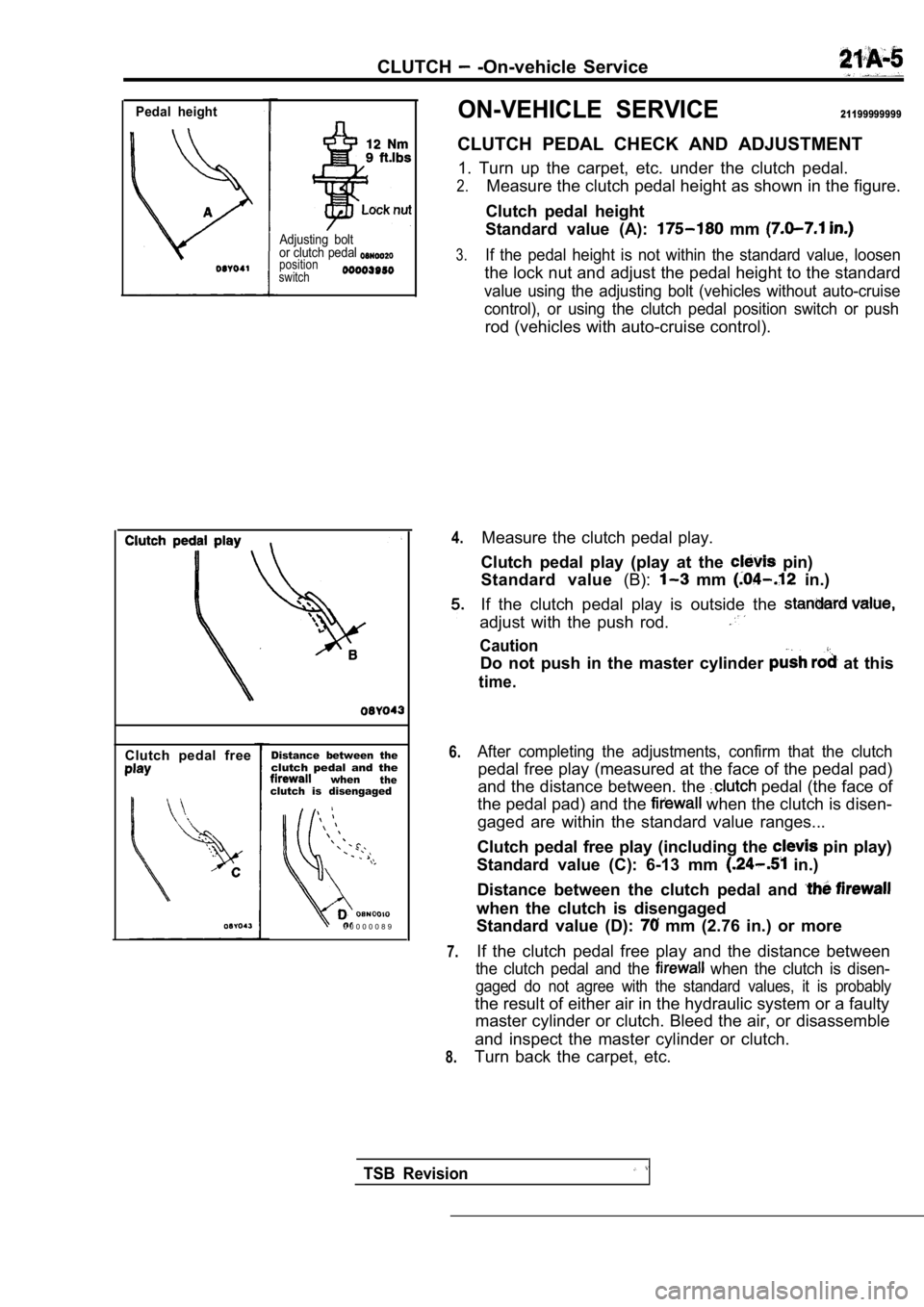
CLUTCH -On-vehicle Service
Pedal height
Adjusting bolt
or clutch pedal
position
switch
Clutch pedal freeDistance between theclutch pedal and thewhentheclutch is disengaged
0 0 0 0 0 0 8 9
ON-VEHICLE SERVICE21199999999
CLUTCH PEDAL CHECK AND ADJUSTMENT
1. Turn up the carpet, etc. under the clutch pedal.
2.Measure the clutch pedal height as shown in the fig ure.
Clutch pedal height
Standard value (A):
mm
3.If the pedal height is not within the standard valu e, loosen
the lock nut and adjust the pedal height to the sta ndard
value using the adjusting bolt (vehicles without au to-cruise
control), or using the clutch pedal position switch or push
rod (vehicles with auto-cruise control).
4.
6.
7.
8.
Measure the clutch pedal play.
Clutch pedal play (play at the
pin)
Standard value (B):
mm in.)
If the clutch pedal play is outside the
adjust with the push rod.
Caution
Do not push in the master cylinder at this
time.
After completing the adjustments, confirm that the clutch
pedal free play (measured at the face of the pedal pad)
and the distance between. the
pedal (the face of
the pedal pad) and the
when the clutch is disen-
gaged are within the standard value ranges...
Clutch pedal free play (including the
pin play)
Standard value (C): 6-13 mm
in.)
Distance between the clutch pedal and
when the clutch is disengaged
Standard value (D):
mm (2.76 in.) or more
If the clutch pedal free play and the distance betw een
the clutch pedal and the when the clutch is disen-
gaged do not agree with the standard values, it is probably
the result of either air in the hydraulic system or a faulty
master cylinder or clutch. Bleed the air, or disass emble
and inspect the master cylinder or clutch.
Turn back the carpet, etc.
TSB Revision
Page 846 of 2103
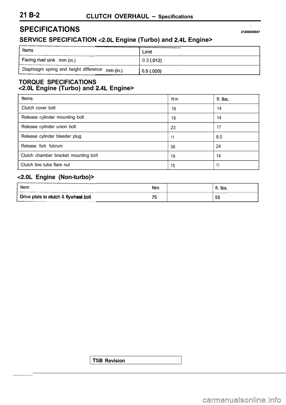
21CLUTCH OVERHAUL Specifications
SPECIFICATIONS21200030047
SERVICE SPECIFICATION Engine (Turbo) and Engine>
0.3
Diaphragm spring end height difference
TORQUE SPECIFICATIONS
Engine (Turbo) and Engine>
Clutch cover bolt
Release cylinder mounting bolt
Release cylinder union bolt
Release cylinder bleeder plug
Release fork fulcrum
Clutch chamber bracket mountingbolt
Clutch line tube flare nut
N mft.
19 14
19
14
23
17
118.0
36 24
1914
1511
Engine (Non-turbo)>
Drive plate to clutch flywheel bolt
Revision
Page 852 of 2103
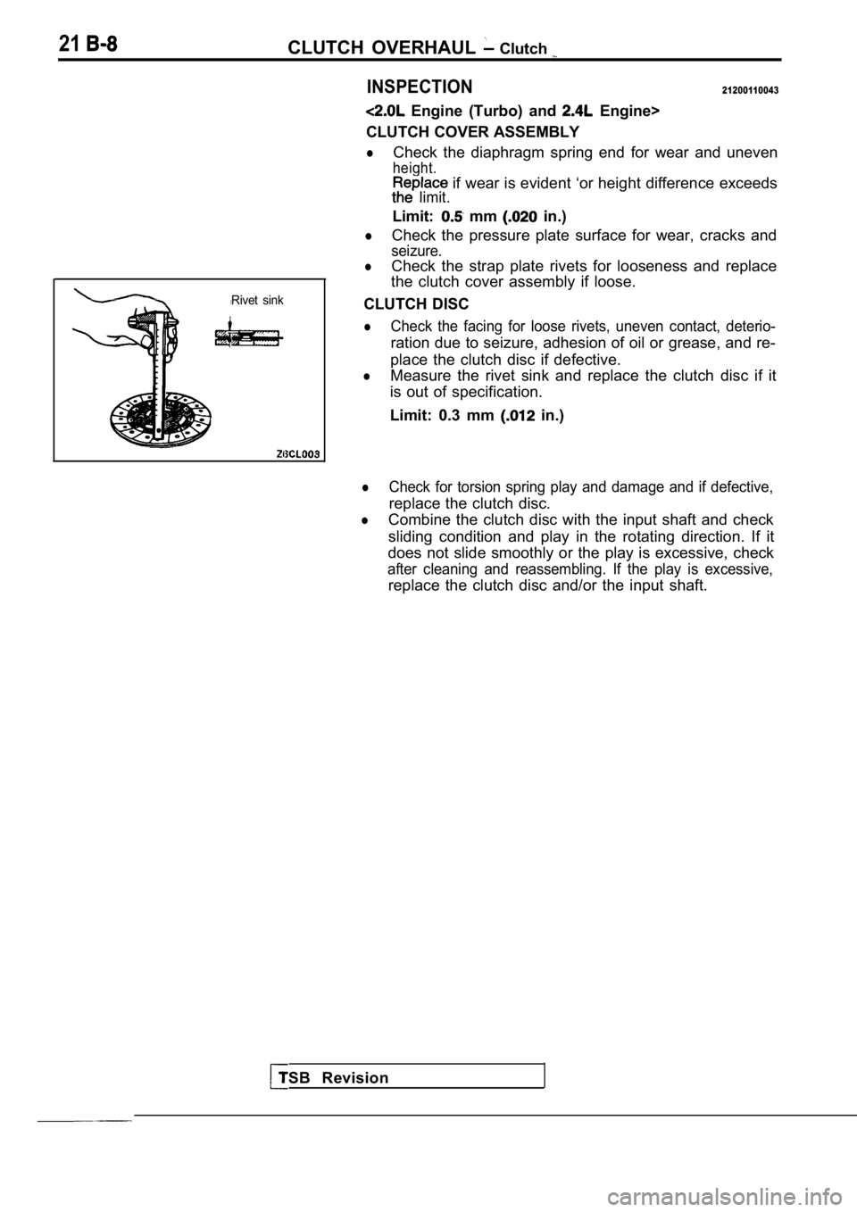
21CLUTCH OVERHAUL Clutch
INSPECTION21200110043
Engine (Turbo) and Engine>
CLUTCH COVER ASSEMBLY
lCheck the diaphragm spring end for wear and uneven
height.
limit. if wear is evident ‘or height difference exceeds
Limit:
mm in.)
lCheck the pressure plate surface for wear, cracks a nd
seizure.
lCheck the strap plate rivets for looseness and replace
the clutch cover assembly if loose.
Rivet sink
TSB Revision
CLUTCH DISC
lCheck the facing for loose rivets, uneven contact, deterio-
ration due to seizure, adhesion of oil or grease, and re-
place the clutch disc if defective.
lMeasure the rivet sink and replace the clutch disc if it
is out of specification.
Limit: 0.3 mm
in.)
lCheck for torsion spring play and damage and if def ective,
replace the clutch disc.
lCombine the clutch disc with the input shaft and ch eck
sliding condition and play in the rotating directio n. If it
does not slide smoothly or the play is excessive, c heck
after cleaning and reassembling. If the play is exc essive,
replace the clutch disc and/or the input shaft.
Page 961 of 2103
MANUAL TRANSAXLE OVERHAUL
(both sides)
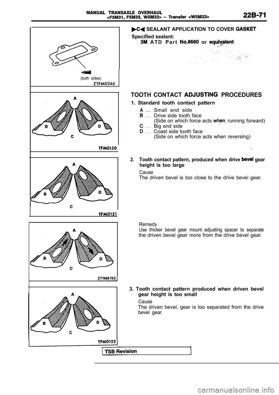
SEALANT APPLICATION TO COVER
Specified sealant:
A T D P a r t or .
TOOTH CONTACT PROCEDURES
1. Standard tooth contact pattern
A. . . .Small end side
. . . .Drive side tooth face
(Side on which force acts running forward)
. . . .Big end side
. . . .Coast side tooth face(Side on which force acts when reversing)
2.Tooth contact pattern, produced when drive gear
height is too large
Cause
The driven bevel is too close to the drive bevei ge ar.
Remedy
Use thicker bevel gear mount adjusting spacer to se parate
the driven bevel gear more from the drive bevel gear.
3. Tooth contact pattern produced when driven bevel gear height is too small
Cause
The driven bevel, gear is too separated from the dr ive
bevel gear.
Page 962 of 2103
MANUAL TRANSAXLE OVERHAUL Transfer
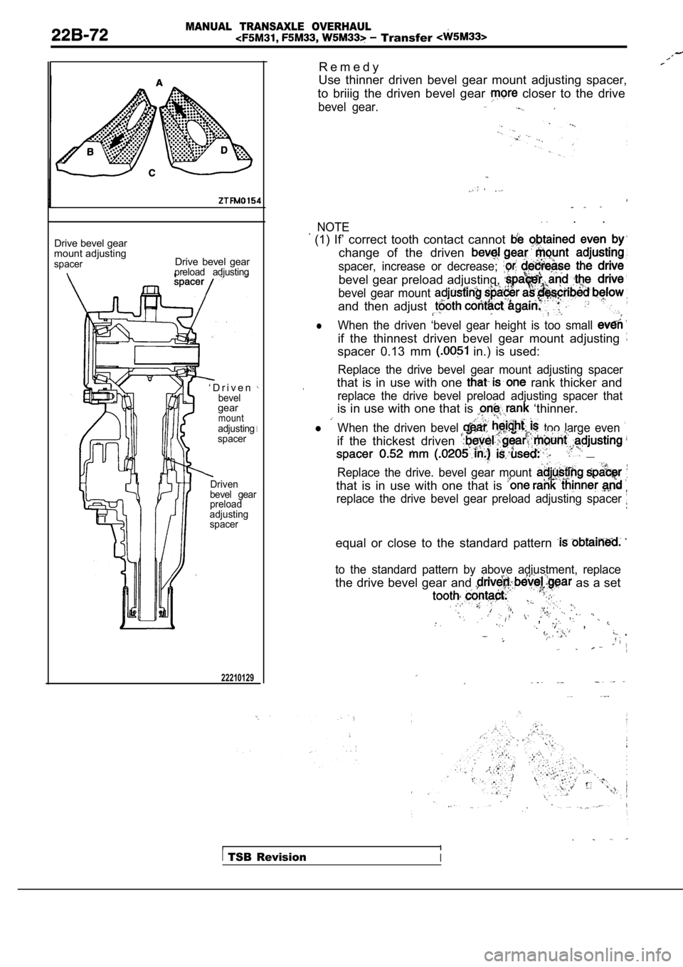
Drive bevel gear
mount adjusting
spacerDrive bevel gearpreload adjusting
‘ D r i v e nbevelgearmountadjusting
spacer
Driven
bevel gear
preload
adjusting
spacer
22210129
R e m e d y
Use thinner driven bevel gear mount adjusting space r,
to briiig the driven bevel gear
closer to the drive
bevel gear.
NOTE . .
(1) If’ correct tooth contact cannot change of the driven
spacer, increase or decrease;
bevel gear preload adjusting,
bevel gear mount
and then adjust
lWhen the driven ‘bevel gear height is too small
if the thinnest driven bevel gear mount adjusting
spacer 0.13 mm in.) is used:
Replace the drive bevel gear mount adjusting spacer
that is in use with one rank thicker and
replace the drive bevel preload adjusting spacer th at
is in use with one that is ‘thinner.
l When the driven bevel too large even
if the thickest driven __
Replace the drive. bevel gear mount
that is in use with one that is
replace the drive bevel gear preload adjusting spacer
equal or close to the standard pattern
to the standard pattern by above adjustment, replac e
the drive bevel gear and as a set
, ,
TSB RevisionI