height MITSUBISHI SPYDER 1990 Service Service Manual
[x] Cancel search | Manufacturer: MITSUBISHI, Model Year: 1990, Model line: SPYDER, Model: MITSUBISHI SPYDER 1990Pages: 2103, PDF Size: 68.98 MB
Page 1676 of 2103
BASIC BRAKE Front Disc . . .
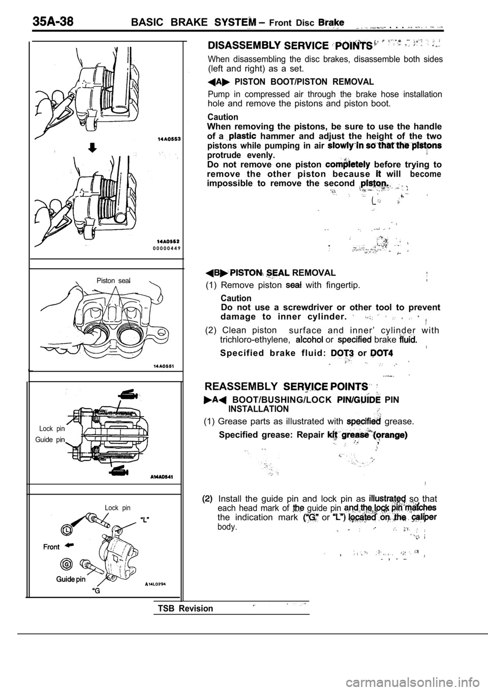
0 0 0 0 0 4 4 9
Piston seal
Lock pin
Guide pin
Lock pin
When disassembling the disc brakes, disassemble both sides
(left and right) as a set.
PISTON BOOT/PISTON REMOVAL
Pump in compressed air through the brake hose insta llation
hole and remove the pistons and piston boot.
Caution
When removing the pistons, be sure to use the handl e
of a
hammer and adjust the height of the two
pistons while pumping in air
protrude evenly.
Do not remove one piston before trying to
remove the other piston because
will
impossible to remove the second become
(_ +-
.
REMOVAL
(1) Remove piston
with fingertip.
Caution
Do not use a screwdriver or other tool to prevent
damage to inner cylinder.
(2) Clean piston s u r f a c e a n d i n n e r ’ c y l i n d e r w i t h
trichloro-ethylene,
or brake
S p e c i f i e d b r a k e f l u i d : or
REASSEMBLY
BOOT/BUSHING/LOCK PIN
INSTALLATION
(1) Grease parts as illustrated with grease.
Specified grease: Repair
,
Install the guide pin and lock pin as so that
each head mark of guide pin
the indication mark or
body..
, , .
TSB Revision
Page 1826 of 2103
BODY Hood
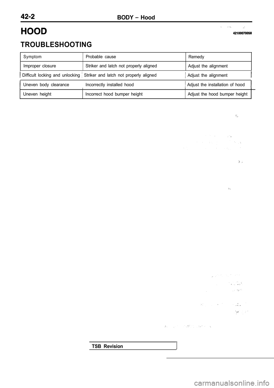
TROUBLESHOOTING
SymptomProbable cause
Improper closure Striker and latch not properly alig nedRemedy
Adjust the alignment
Difficult locking and unlocking Striker and latch not properly aligned Adjust the alignment
Uneven body clearance Incorrectly installed hood Adjust the installation of hood
Uneven heightIncorrect hood bumper height Adjust the hood bumper height
TSB Revision
Page 1827 of 2103
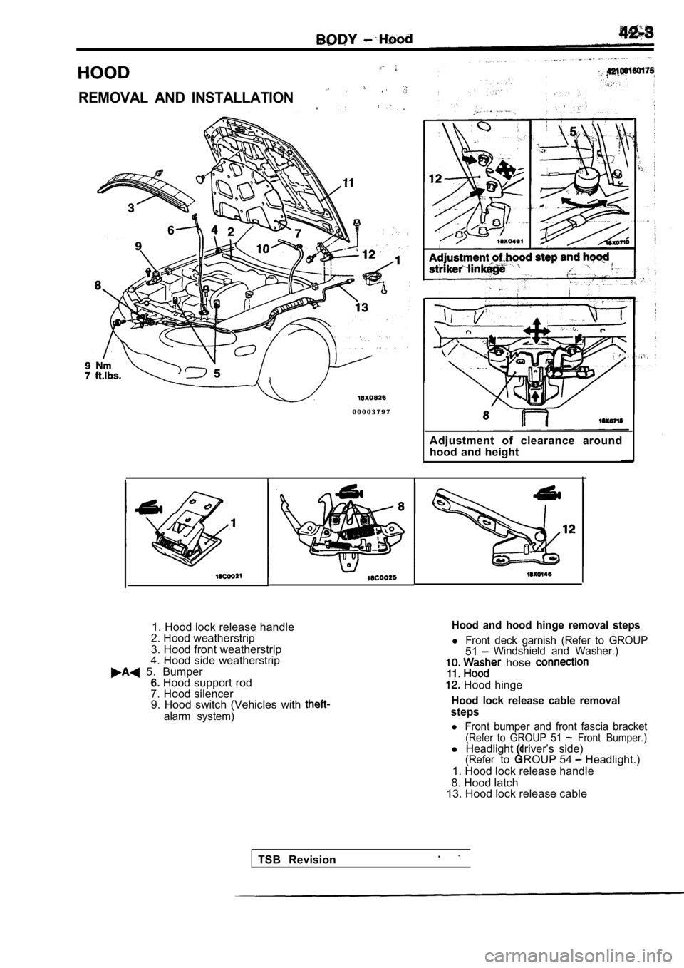
REMOVAL AND INSTALLATION
0 0 0 0 3 7 9 7Adjustment of clearance around
hood and height
1. Hood lock release handle
2. Hood weatherstrip
3. Hood front weatherstrip
4. Hood side weatherstrip
5. Bumper 6. Hood support rod
7. Hood silencer 9. Hood switch (Vehicles with
alarm system)
Hood and hood hinge removal steps
l Front deck garnish (Refer to GROUP51Windshield and Washer.)
hose
Hood hinge
Hood lock release cable removal
steps
l Front bumper and front fascia bracket(Refer to GROUP 51 Front Bumper.)l Headlight driver’s side)(Refer toROUP 54 Headlight.)
1. Hood lock release handle
8. Hood latch
13. Hood lock release cable
TSB Revision .
Page 1831 of 2103
BODY and Window Glass
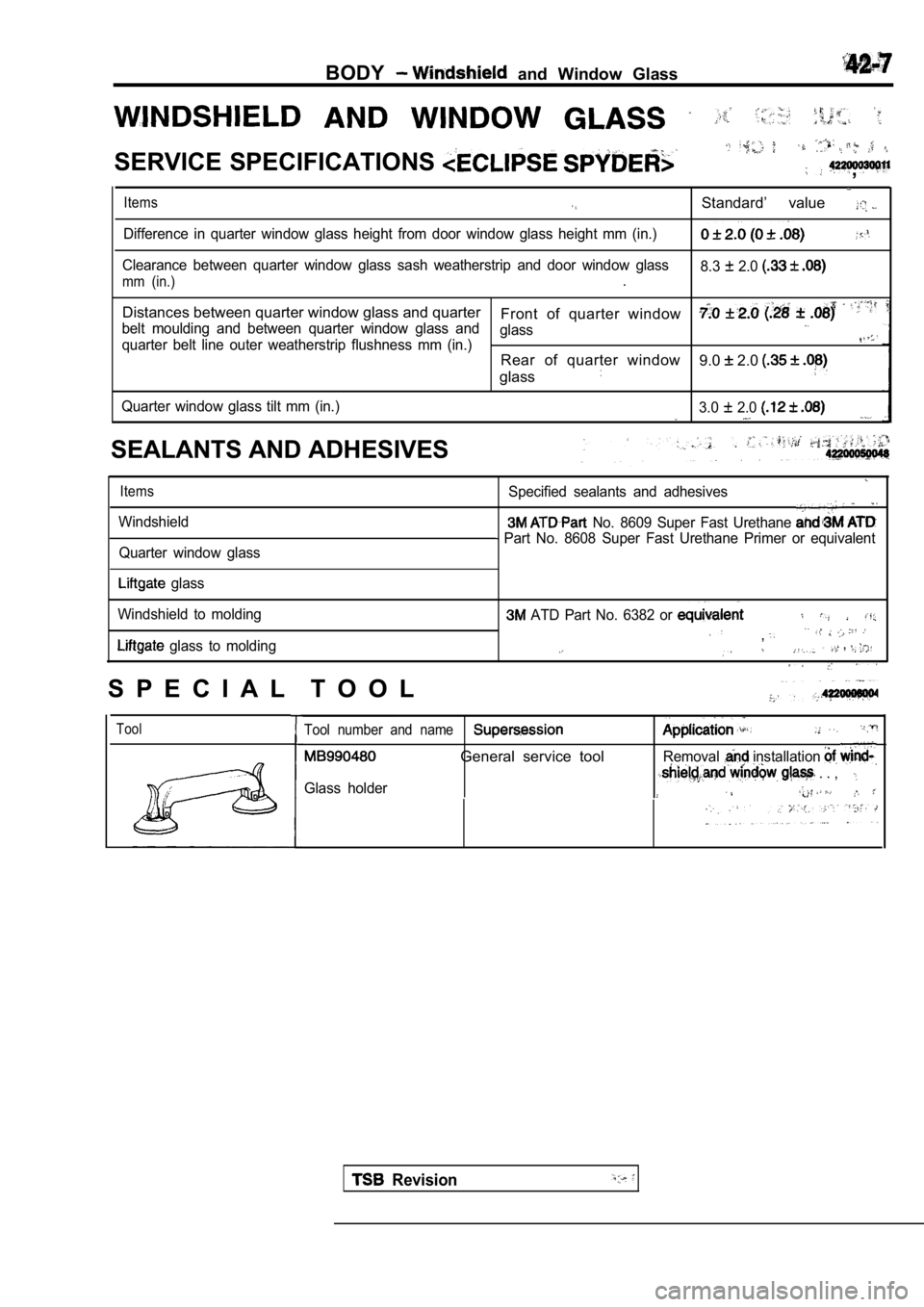
SERVICE SPECIFICATIONS ,
Items
Difference in quarter window glass height from door window glass height mm (in.)
Clearance between quarter window glass sash weather strip and door window glass
mm (in.).Standard’ value 8.3 2.0
Distances between quarter window glass and quarter
Front of quarter window
belt moulding and between quarter window glass and glass
quarter belt line outer weatherstrip flushness mm (in.)Rear of quarter window
glass9.0 2.0
Quarter window glass tilt mm (in.) 3.0 2.0
SEALANTS AND ADHESIVES
Items
Windshield
Quarter window glass
Specified sealants and adhesives
No. 8609 Super Fast Urethane
Part No. 8608 Super Fast Urethane Primer or equiva lent
glass
Windshield to molding
glass to molding
ATD Part No. 6382 or
,. . , . .
S P E C I A L T O O L
ToolTool number and name
General service toolRemoval installation
Glass holder . . ,
Revision
Page 1835 of 2103
and Window Glass
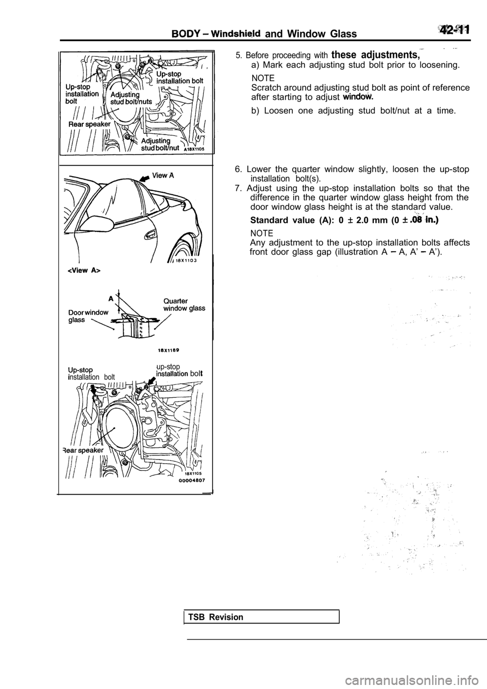
installation bolt
up-stop bolt
5. Before proceeding with these adjustments,
a) Mark each adjusting stud bolt prior to loosening.
NOTE
Scratch around adjusting stud bolt as point of reference
after starting to adjust
b) Loosen one adjusting stud bolt/nut at a time.
6. Lower the quarter window slightly, loosen the up -stop
installation bolt(s).
7. Adjust using the up-stop installation bolts so that the
difference in the quarter window glass height from the
door window glass height is at the standard value.
Standard value (A): 0 2.0 mm (0
NOTE
Any adjustment to the up-stop installation bolts af fects
front door glass gap (illustration A
A, A’ A’).
TSB Revision
Page 1836 of 2103
BODY Windshield and Window Glass
A
Section
Quarter
Door window glassSash weatherstrip
up-stopup-stopinstallation bolt
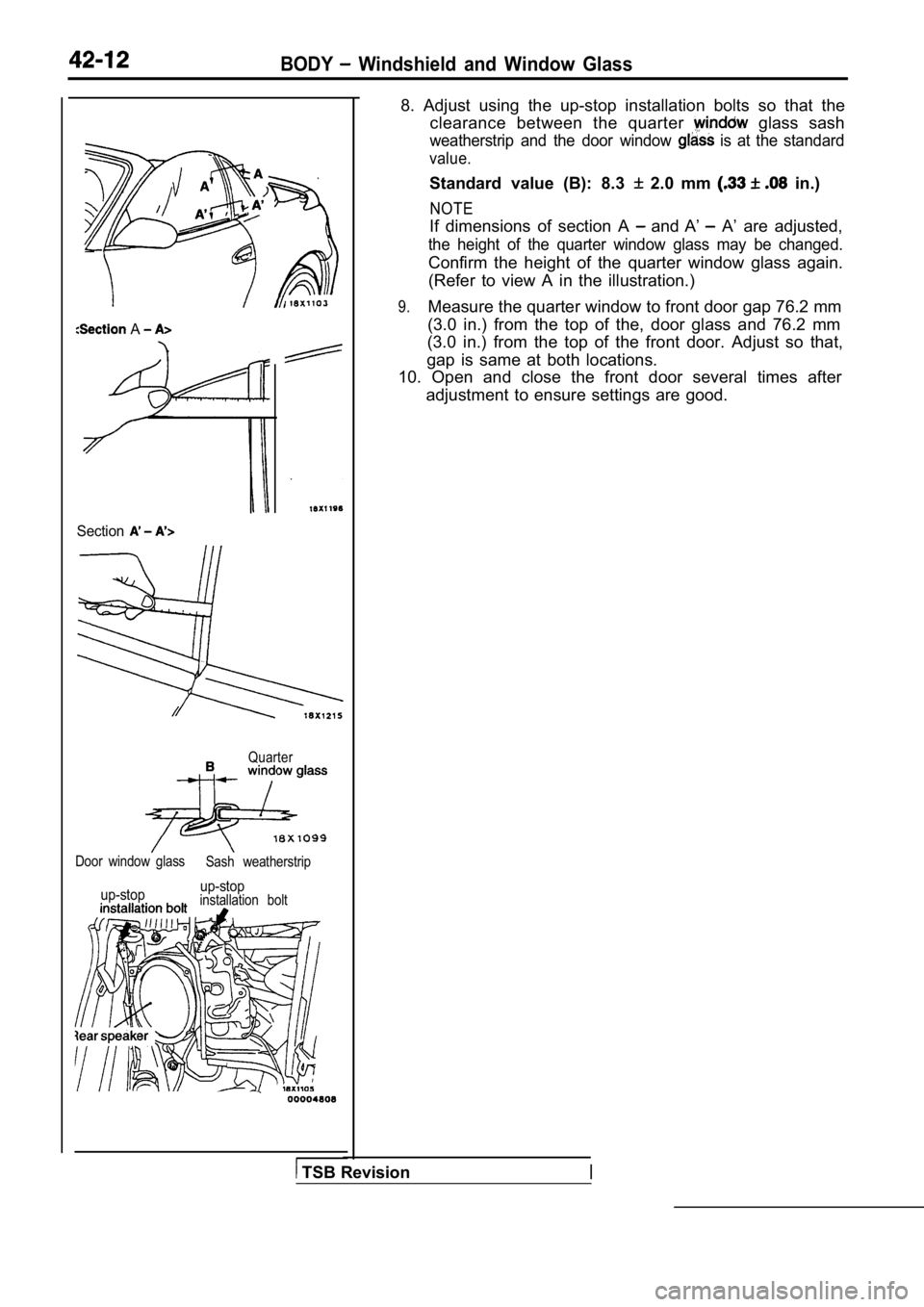
8. Adjust using the up-stop installation bolts so t
hat the
clearance between the quarter
glass sash
weatherstrip and the door window is at the standard
value.
Standard value (B): 8.3 2.0 mm in.)
NOTE
If dimensions of section A and A’ A’ are adjusted,
the height of the quarter window glass may be chang ed.
Confirm the height of the quarter window glass again.
(Refer to view A in the illustration.)
9.Measure the quarter window to front door gap 76.2 m m
(3.0 in.) from the top of the, door glass and 76.2 mm
(3.0 in.) from the top of the front door. Adjust so that,
gap is same at both locations.
10. Open and close the front door several times aft er
adjustment to ensure settings are good.
TSB Revision
Page 1874 of 2103
Section A-A
Section B-B
Section C-C
9. Tighten the three delta sash mounting bolts so t hat the
edges of the delta sash and window glass run on smo othly
with there being no difference in height at the lip end.
10. Install the drip line weatherstrip to the weatherstrip holder.
Caution
The weatherstrip should not slip or become wrinkled .’
11. Open and close the door and raise and lower the window
glass and check the glass installation against the following
points.
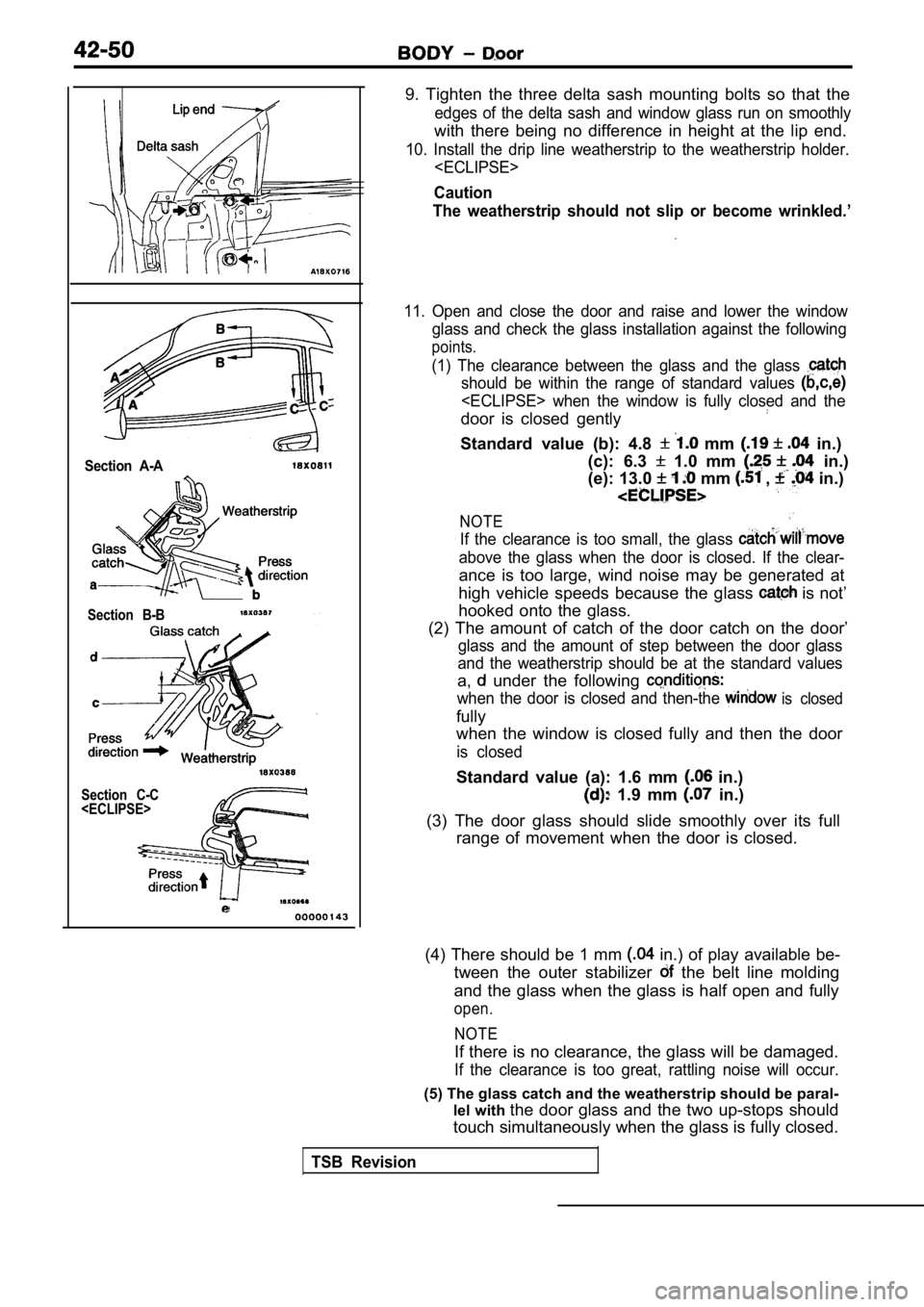
(1) The clearance between the glass and the glass
should be within the range of standard values
door is closed gently
Standard value (b): 4.8 mm in.)
(c): 6.3
1.0 mm in.)
(e): 13.0
mm , in.)
NOTE
If the clearance is too small, the glass
above the glass when the door is closed. If the cle ar-
ance is too large, wind noise may be generated at
high vehicle speeds because the glass
is not’
hooked onto the glass.
(2) The amount of catch of the door catch on the do or’
glass and the amount of step between the door glass
and the weatherstrip should be at the standard valu es
a, under the following
when the door is closed and then-the is closed
fully
when the window is closed fully and then the door
is closed
Standard value (a): 1.6 mm in.)
1.9 mm in.)
(3) The door glass should slide smoothly over its f ull
range of movement when the door is closed.
(4) There should be 1 mm
in.) of play available be-
tween the outer stabilizer
the belt line molding
and the glass when the glass is half open and fully
open.
NOTE
If there is no clearance, the glass will be damaged .
If the clearance is too great, rattling noise will occur.
(5) The glass catch and the weatherstrip should be paral-
lel with the door glass and the two up-stops should
touch simultaneously when the glass is fully closed .
TSB Revision
Page 1889 of 2103

BODY
TROUBLESHOOTING
SymptomImproper closure
Difficult locking and unlocking
Uneven body clearance
UnevenProbable cause Remedy
Striker and latch not properly aligned Adjust the al ignment
Striker and latch not properly aligned
Adjust the alignment
Incorrectly installed Adjust the installation of
Incorrect bumper height Adjust the bumper height
TSB Revision
Page 1892 of 2103
TRUNK LID
B O D Y Trunk Lid
TROUBLESHOOTING
Improper closure Striker and latch not properly aligned
Adjust the alignment
Difficult locking and unlocking.
Uneven body clearance Incorrectly installed trunk lid
Adjust the installation of trunk lid
Uneven height Incorrect trunk lid bumper height Adjust the trunk lid bumper height
TSB Revision
Page 1978 of 2103
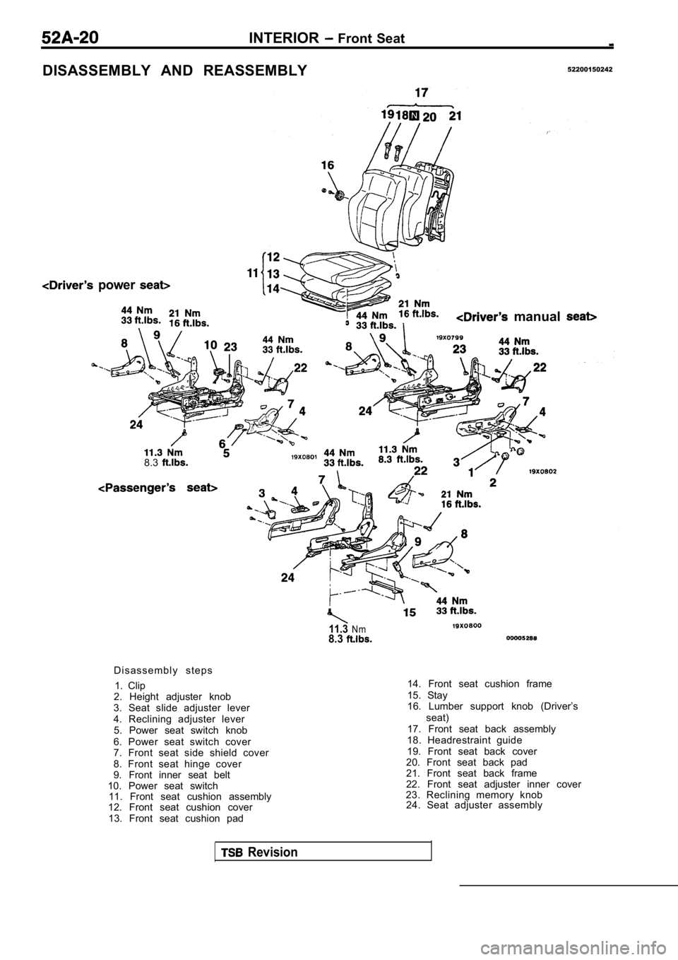
INTERIOR Front Seat
DISASSEMBLY AND REASSEMBLY52200150242
power
manual
8.3
11.3Nm8.3
D i s a s s e m b l y s t e p s1. Clip
2. Height adjuster knob
3. Seat slide adjuster lever
4. Reclining adjuster lever 5. Power seat switch knob
6. Power seat switch cover
7. Front seat side shield cover
8. Front seat hinge cover
9. Front inner seat belt
10. Power seat switch 11. Front seat cushion assembly
12. Front seat cushion cover
13. Front seat cushion pad 14. Front seat cushion frame
15. Stay
16. Lumber support knob (Driver’s
seat)
17. Front seat back assembly
18. Headrestraint guide
19. Front seat back cover
20. Front seat back pad
21. Front seat back frame
22. Front seat adjuster inner cover
23. Reclining memory knob 24. Seat adjuster assembly
Revision