sensor MITSUBISHI SPYDER 1990 Service Repair Manual
[x] Cancel search | Manufacturer: MITSUBISHI, Model Year: 1990, Model line: SPYDER, Model: MITSUBISHI SPYDER 1990Pages: 2103, PDF Size: 68.98 MB
Page 1468 of 2103
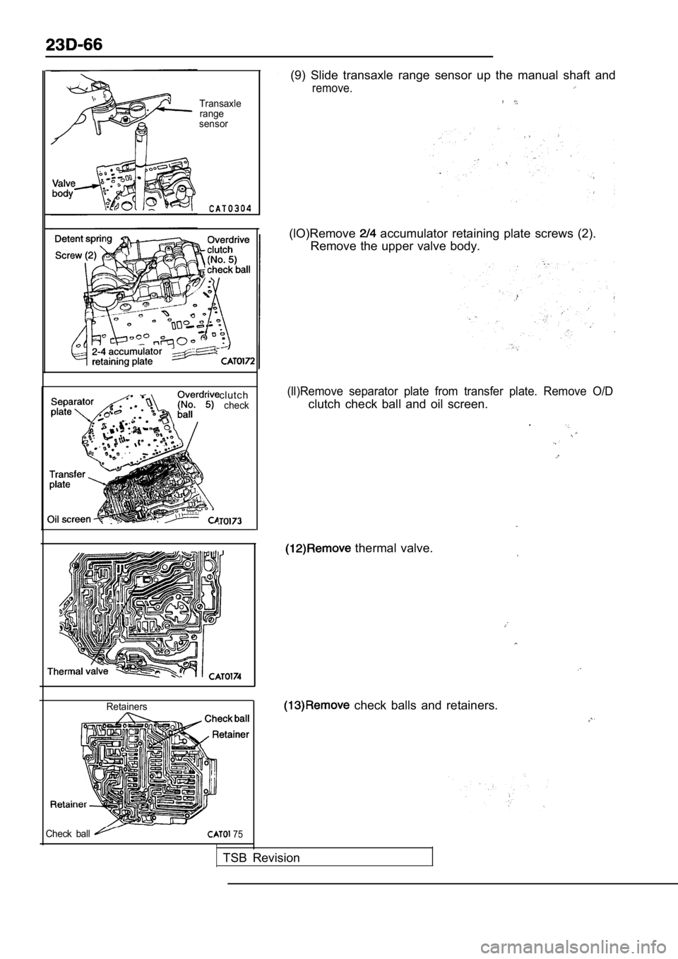
Transaxlerange
sensor
clutchcheck
Retainers
(9) Slide transaxle range sensor up the manual shaf t and
remove.,
(lO)Remove accumulator retaining plate screws (2).
Remove the upper valve body.
(ll)Remove separator plate from transfer plate. Rem ove O/D
clutch check ball and oil screen.
.
thermal valve.
check balls and retainers.
Check ball 75
TSB Revision
Page 1510 of 2103
26-6FRONT AXLE Front
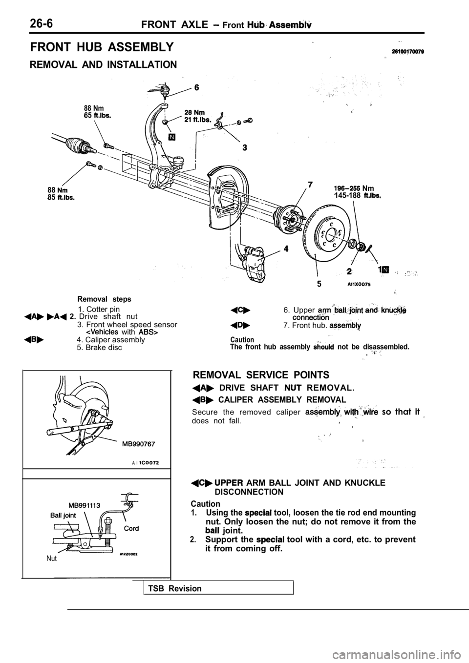
FRONT HUB ASSEMBLY
REMOVAL AND INSTALLATION
88 Nm65
8885
Removal steps
1. Cotter pin 2. Drive shaft nut
3. Front wheel speed sensor
with 4. Caliper assembly
5. Brake disc
A l
Nut
Nm
145-188
5
Caution
6. Upper
7. Front hub.
The front hub assembly not be disassembled..
REMOVAL SERVICE POINTS
DRIVE SHAFT R E M O V A L .
CALIPER ASSEMBLY REMOVAL
Secure the removed caliper so that it
does not fall., ,
ARM BALL JOINT AND KNUCKLE
DISCONNECTION
Caution
1.Using the tool, loosen the tie rod end mounting
nut. Only loosen the nut; do not remove it from the
joint.
2.Support the tool with a cord, etc. to prevent
it from coming off.
TSB Revision
Page 1536 of 2103
General Information/Service Specifications/
REAR AXLE Special Tools
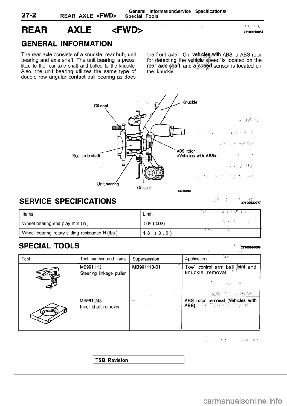
The rear axle consists of a knuckle, rear hub, unit
bearing and axle shaft. The unit bearing is
fitted to the rear axle shaft and bolted to the knuckle.
Also, the unit bearing utilizes the same type of
double row angular contact ball bearing as does
the front axle.
On, ABS, a ABS rotor
for detecting the speed is located on the
and sensor is located on
the knuckle.
Rear rotor
UnitOil seal
Items
Wheel bearing end play mm (in.)
Wheel bearing rotary-sliding resistance
(Ibs.) Limit
, ,
0.05
1 8 ( 3 . 9 )
ToolTool number and name
113
Steering linkage puller
248
Inner shaft remover
Supersession Application,
Toe’ arm ball and
k n u c k l e r e m o v a l ’
.
I
. .
TSB Revision
Page 1539 of 2103
REAR AXLE Rear Hub Assembly
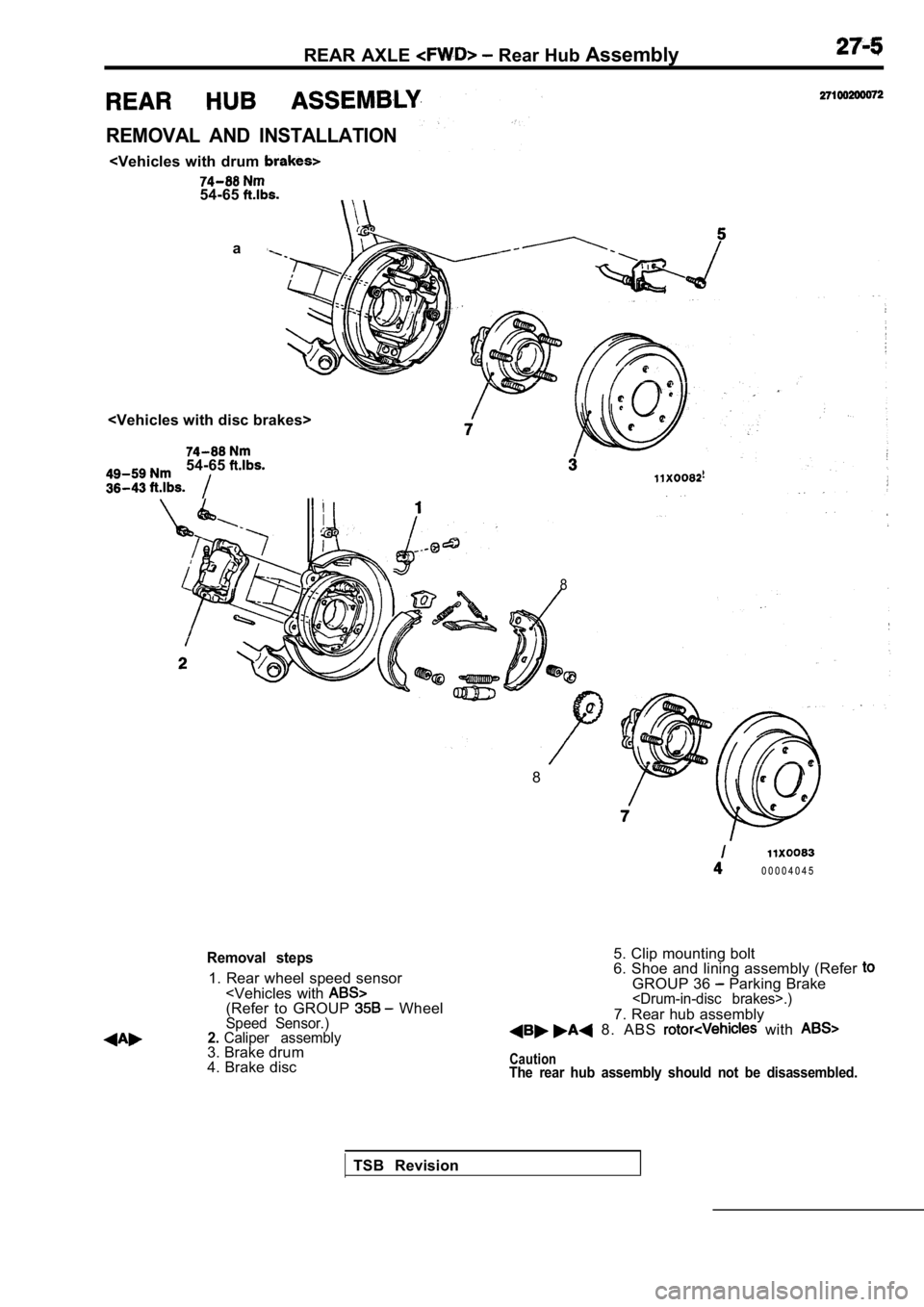
REMOVAL AND INSTALLATION
a
54-65
8
8
0 0 0 0 4 0 4 5
Removal steps
1. Rear wheel speed sensor
4. Brake disc 5. Clip mounting bolt
6. Shoe and lining assembly (Refer
GROUP 36 Parking Brake
7. Rear hub assembly 8. ABS with
CautionThe rear hub assembly should not be disassembled.
TSB Revision
Page 1541 of 2103
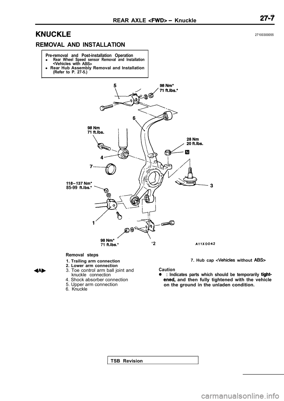
REAR AXLE Knuckle
REMOVAL AND INSTALLATION
27100300055
Pre-removal and Post-installation OperationlRear Wheel Speed sensor Removal and Installation
71‘2
Removal steps
1. Trailing arm connection
2. Lower arm connection
3. Toe control arm ball joint and
knuckle connection
4. Shock absorber connection
5. Upper arm connection
6. Knuckle
Caution
7. Hub cap without
l : Indicates parts which should be temporarily
and then fully tightened with the vehicle
on the ground in the unladen condition.
TSB Revision
Page 1543 of 2103
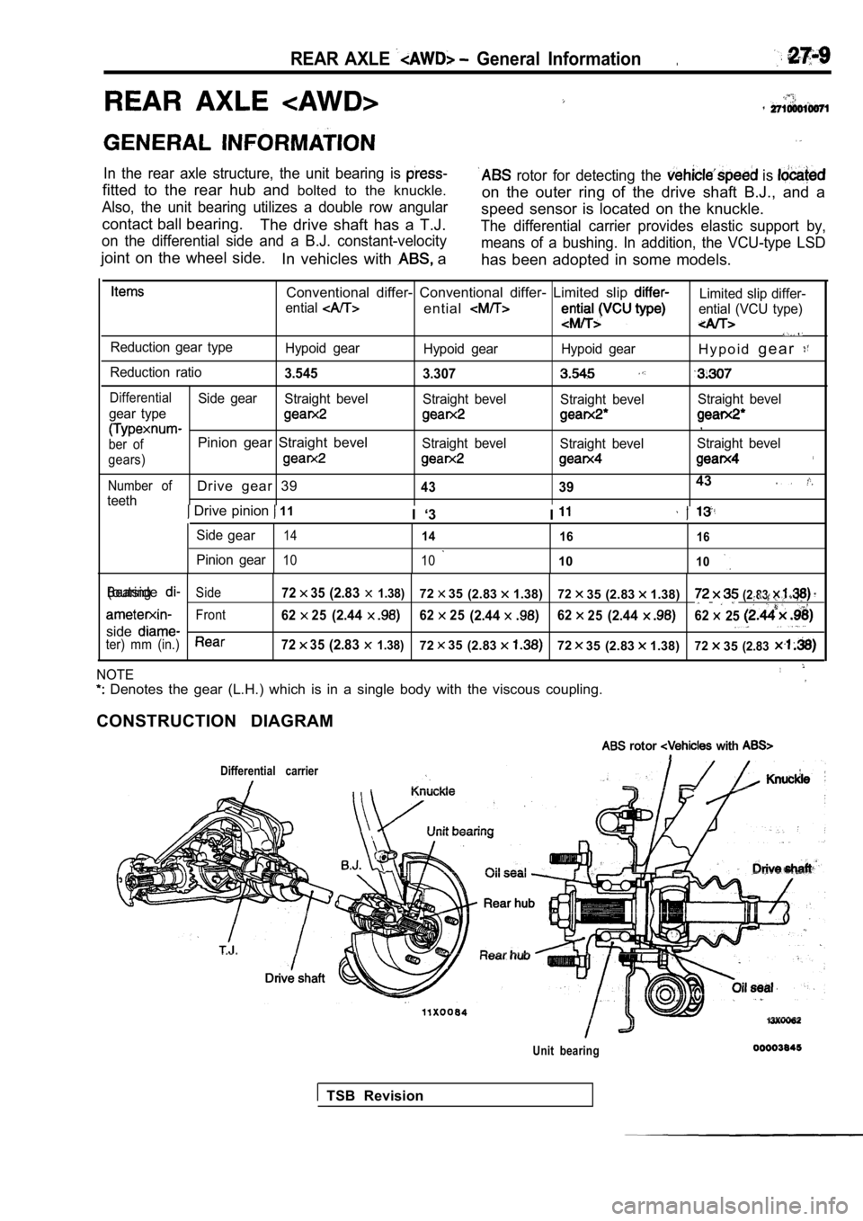
REAR AXLE General Information.
In the rear axle structure, the unit bearing is
fitted to the rear hub and bolted to the knuckle.
Also, the unit bearing utilizes a double row angula r
contact ball bearing.
The drive shaft has a T.J.
on the differential side and a B.J. constant-veloci ty
joint on the wheel side.
In vehicles with a
rotor for detecting the is
on the outer ring of the drive shaft B.J., and a
speed sensor is located on the knuckle.
The differential carrier provides elastic support b y,
means of a bushing. In addition, the VCU-type LSD
has been adopted in some models.
Conventional differ- Conventional differ- Limited s lip Limited slip differ-
ential
entialential (VCU type)
Reduction gear type Hypoid gearHypoid gear Hypoid gearH y p o i dg e a r
Reduction ratio3.545
3.307
DifferentialSide gearStraight bevel Straight bevelStraight bevelStraight bevel
gear type
,
ber ofPinion gear Straight bevelStraight bevel Straight bevelStraight bevel
gears)
Number ofDrive gear 39433943
teeth Drive pinion 11
I ‘3 I
Sidegear1414 1616
Pinion gear10 101010
BearingSide7235(2.83 1.38)7235(2.831.38)7235 (2.83 1.38)(outside(2.83 ,
Front6225(2.446225(2.446225(2.4462 25
sideter) mm (in.)7235(2.83 1.38)7235(2.837235 (2.83 1.38)72 35(2.83
NOTE
Denotes the gear (L.H.) which is in a single body with the viscous coupling.
CONSTRUCTION DIAGRAM
rotor with
Differential carrier
Unit bearing
TSB Revision
Page 1552 of 2103
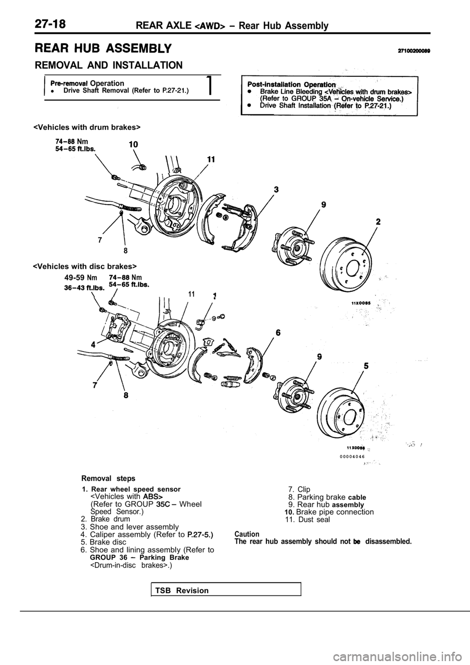
REAR AXLE Rear Hub Assembly
REMOVAL AND INSTALLATION
OperationlDrive Shaft Removal (Refer to 1
Nm
7
8
NmNm
11
Removal steps
1. Rear wheel speed sensor
2. Brake drum
3. Shoe and lever assembly
4. Caliper assembly (Refer to
5. Brake disc
6. Shoe and lining assembly (Refer to GROUP 36
Parking Brake
0 0 0 0 4 0 4 6
7. Clip8. Parking brake cable
9. Rear hub assembly
10. Brake pipe connection
11. Dust seal
CautionThe rear hub assembly should not disassembled.
TSB Revision
Page 1554 of 2103
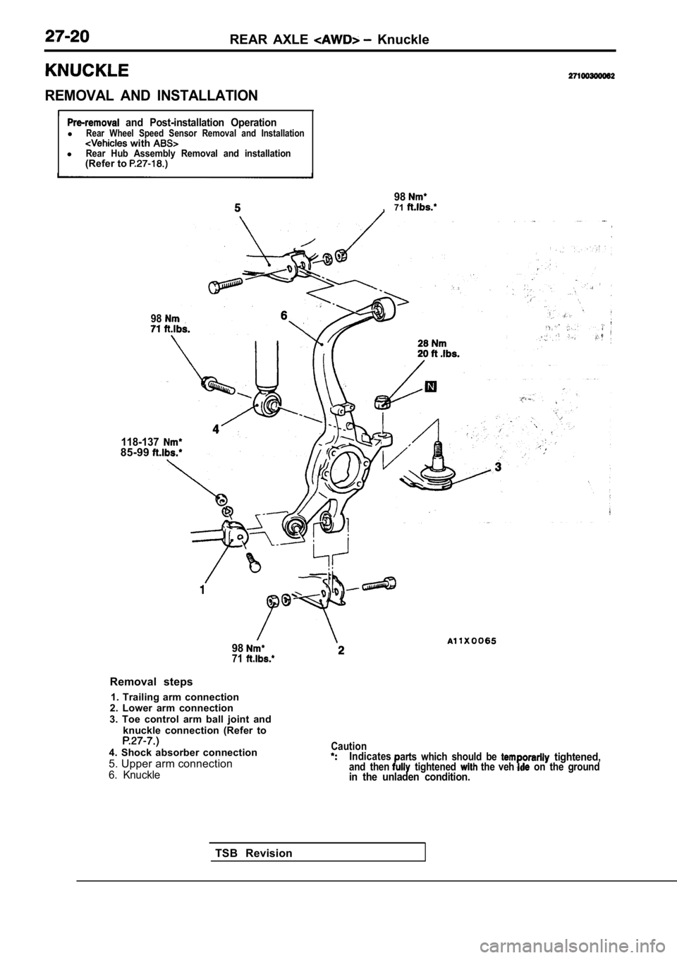
REAR AXLE Knuckle
REMOVAL AND INSTALLATION
II and Post-installation OperationlRear Wheel Speed Sensor Removal and Installation with lRear Hub Assembly Removal and installation(Refer to
98, 71
98
118-13785-99
TSB Revision
9871
Removal steps
1. Trailing arm connection
2. Lower arm connection
3. Toe control arm ball joint and knuckle connection (Refer to
4. Shock absorber connection
5. Upper arm connection
6. Knuckle
CautionIndicates
and thenarts which should be tightened, tightened the veh on the groundin the unladen condition.
Page 1555 of 2103
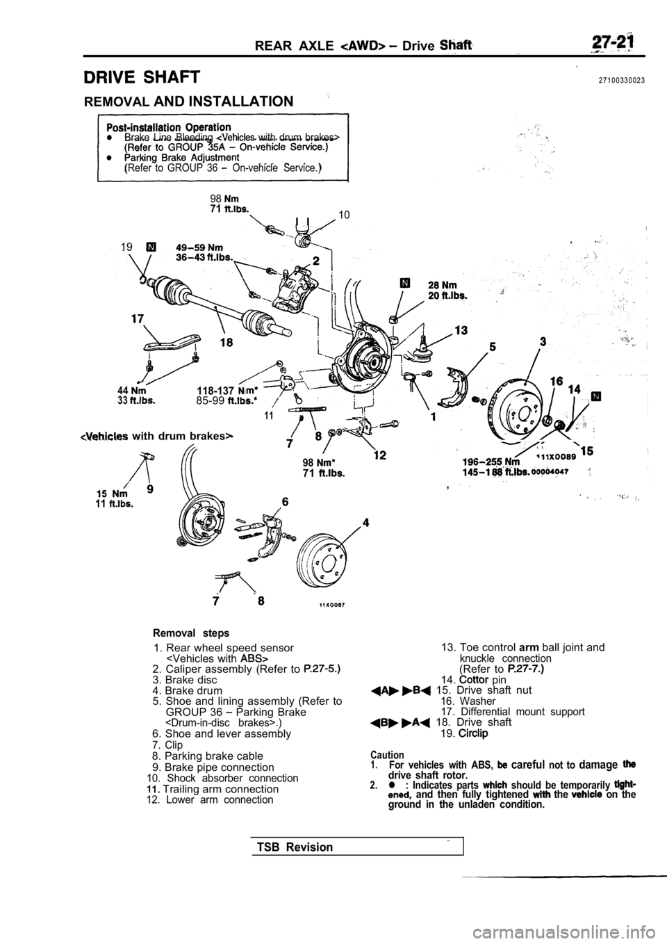
REAR AXLE Drive
2 7 1 0 0 3 3 0 0 2 3
REMOVAL AND INSTALLATION
Brake Line Bleeding with drum brakes>
(Refer to GROUP 36
On-vehicle Service.)
9871
I I10
,19
44118-1373385-99
11
with drum brakes>
11
9871. .,
Removal steps
1. Rear wheel speed sensor
4. Brake drum
5. Shoe and lining assembly (Refer to
GROUP 36
Parking Brake
7. Clip8. Parking brake cable
9. Brake pipe connection
10. Shock absorber connection Trailing arm connection12. Lower arm connection
13. Toe control armball joint andknuckle connection(Refer to 14. pin 15. Drive shaft nut16. Washer
17. Differential mount support
18. Drive shaft
19.
Caution1.For vehicles with ABS, careful not to damagedrive shaft rotor.2.l : Indicates parts should be temporarily and then fully tightened the on the
ground in the unladen condition.
TSB Revision
Page 1563 of 2103
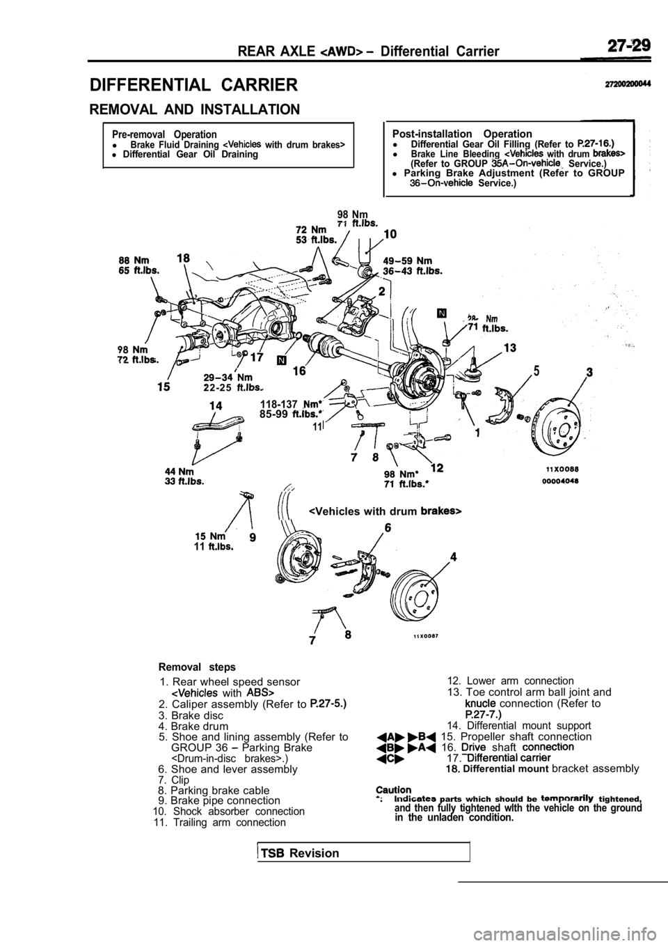
REAR AXLE Differential Carrier
DIFFERENTIAL CARRIER
REMOVAL AND INSTALLATION
Pre-removal OperationlBrake Fluid Draining with drum brakes>l Differential Gear Oil Draining
98 Nm
Post-installation OperationlDifferential Gear Oil Filling (Refer to lBrake Line Bleeding with drum (Refer to GROUP Service.)l Parking Brake Adjustment (Refer to GROUP Service.)
98
2 2 - 2 5
118-13785-99
11
5
11
Removal steps
1. Rear wheel speed sensor
with 2. Caliper assembly (Refer to
3. Brake disc
4. Brake drum
5. Shoe and lining assembly (Refer to
GROUP 36
Parking Brake
10. Shock absorber connection
11. Trailing arm connection 12. Lower arm connection
13. Toe control arm ball joint and
connection (Refer to
14. Differential mount support 15. Propeller shaft connection 16. shaft 17. Differential mount
bracket assembly
parts which should be tightened,and then fully tightened wlth the vehicle on the gr oundin the unladen condition.
Revision