sensor MITSUBISHI SPYDER 1990 Service Repair Manual
[x] Cancel search | Manufacturer: MITSUBISHI, Model Year: 1990, Model line: SPYDER, Model: MITSUBISHI SPYDER 1990Pages: 2103, PDF Size: 68.98 MB
Page 1221 of 2103
39.
40.
41.
44:
45.
46.
47.
50.
51.
52. 53.
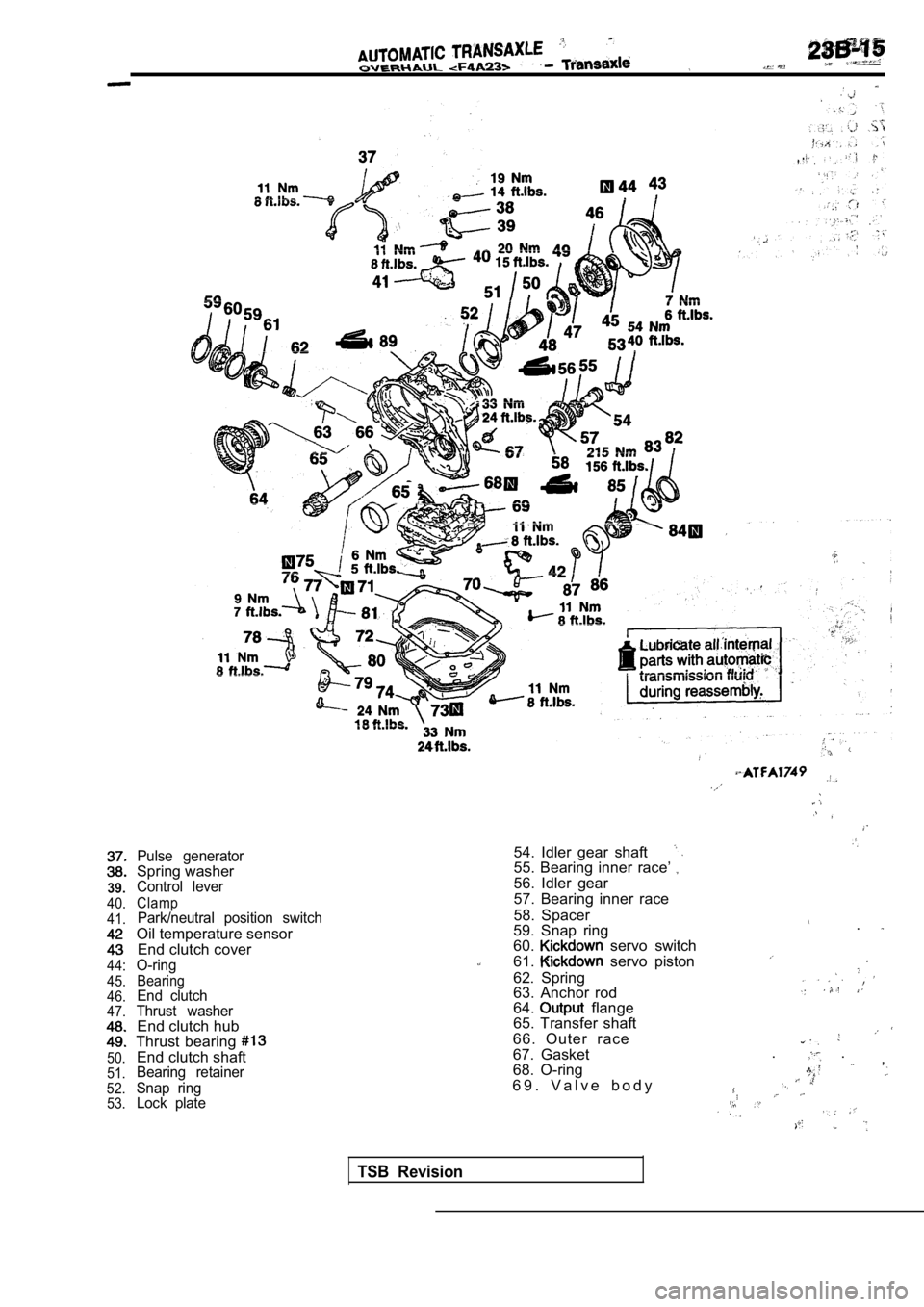
Pulse generatorSpring washerControl lever
ClampPark/neutral position switch
Oil temperature sensor
End clutch cover
O-ring
BearingEnd clutch
Thrust washer
End clutch hub
Thrust bearing
End clutch shaftBearing retainer
Snap ring Lock plate
54. Idler gear shaft55. Bearing inner race’
56. Idler gear
57. Bearing inner race
58. Spacer
59. Snap ring .60. servo switch
61. servo piston
62. Spring
63. Anchor rod64. flange
65. Transfer shaft
66. Outer race
67. Gasket . .
,
68. O-ring
6 9 . V a l v e b o d y
TSB Revision
Page 1223 of 2103
A U T O M A T I C T R A N S A X L EOVERHAUL Transaxle
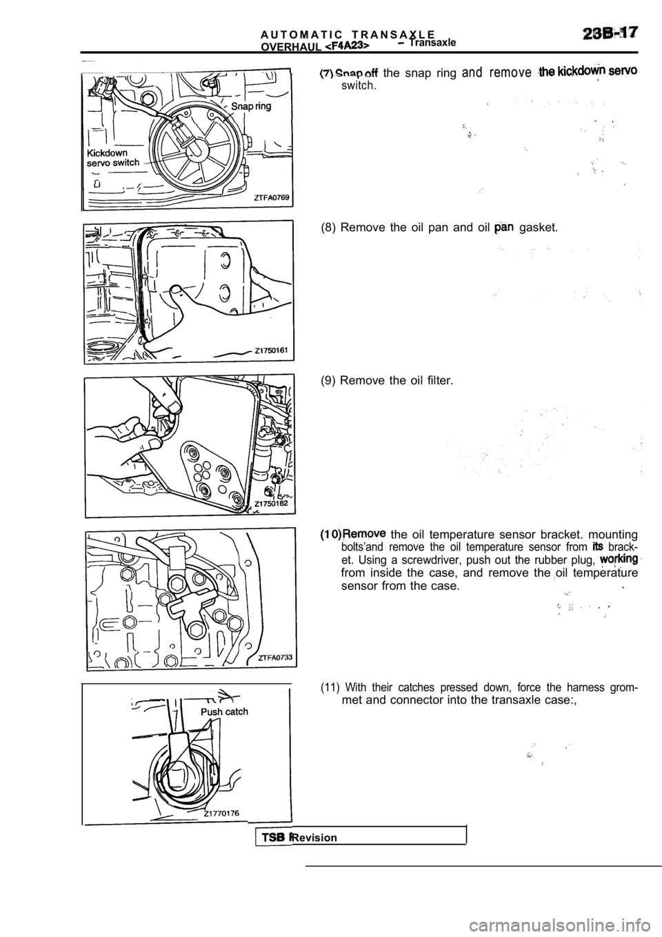
the snap ring and remove
switch.
(8) Remove the oil pan and oil gasket.
(9) Remove the oil filter.
the oil temperature sensor bracket. mounting
bolts’and remove the oil temperature sensor from brack-
et. Using a screwdriver, push out the rubber plug,
from inside the case, and remove the oil temperatur e
sensor from the case..
(11) With their catches pressed down, force the har
ness grom-
met and connector into the transaxle case:,
TSB Revision
Page 1304 of 2103
AUTOMATIC TRANSAXLE
OVERHAUL,
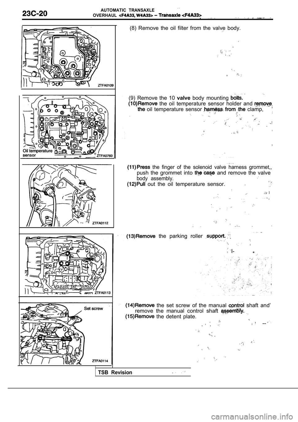
(8) Remove the oil filter from the valve body.
.
,
(9) Remove the 10 valvebody mounting
the oil temperature sensor holder and
oil temperature sensor clamp,
,
the finger of the solenoid valve harness grommet,,
push the grommet into and remove the valve
body assembly.
out the oil temperature sensor.
the parking roller
I-
*
the set screw of the manual shaft and’
remove the manual control shaft
the detent plate.
--. .
TSB Revision
Page 1325 of 2103
AUTOMATIC
OVERHAUL Transaxle
A
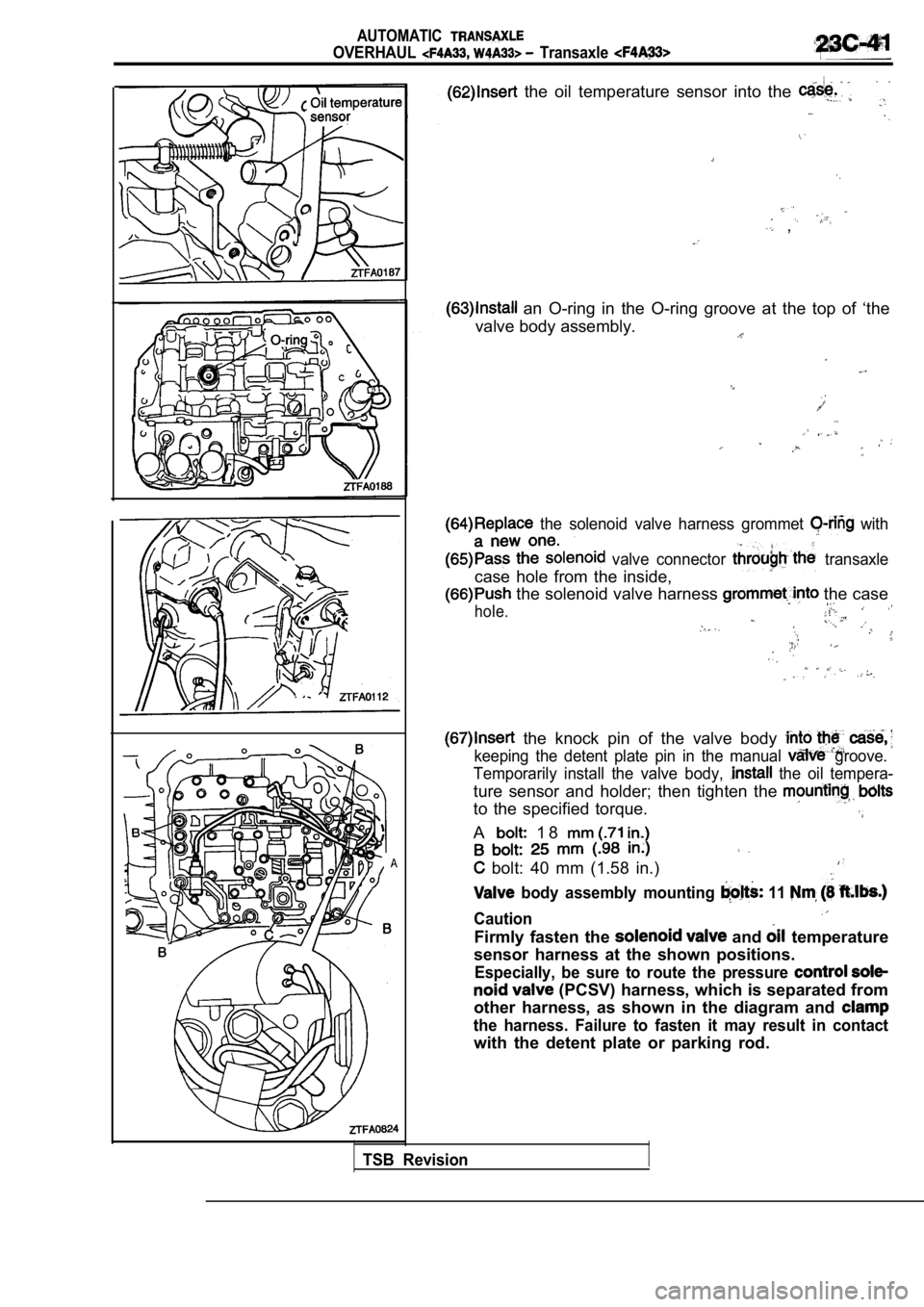
the oil temperature sensor into the
,
an O-ring in the O-ring groove at the top of ‘the
valve body assembly.
the solenoid valve harness grommet with
valve connector transaxle
case hole from the inside,
the solenoid valve harness the case
hole.
the knock pin of the valve body
keeping the detent plate pin in the manual groove.
Temporarily install the valve body,
the oil tempera-
ture sensor and holder; then tighten the
to the specified torque.
A 1 8
bolt: 40 mm (1.58 in.)
body assembly mounting 11
Caution
Firmly fasten the and temperature
sensor harness at the shown positions.
Especially, be sure to route the pressure
(PCSV) harness, which is separated from
other harness, as shown in the diagram and
the harness. Failure to fasten it may result in con tact
with the detent plate or parking rod.
TSB Revision
Page 1332 of 2103
AUTOMATIC TRANSAXLE
OVERHAUL -Transaxle
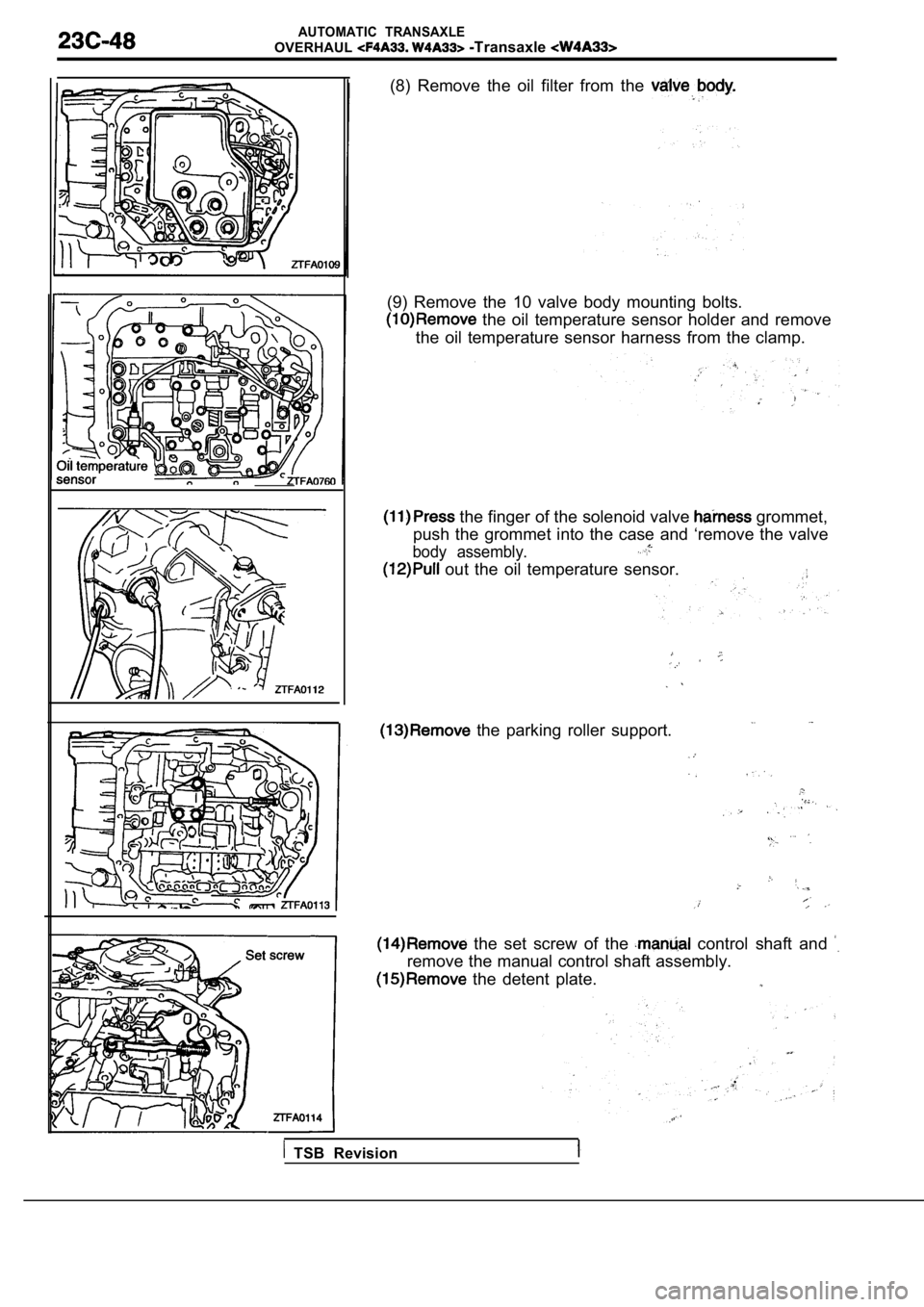
(8) Remove the oil filter from the
(9) Remove the 10 valve body mounting bolts.
the oil temperature sensor holder and remove
the oil temperature sensor harness from the clamp.
the finger of the solenoid valve grommet,
push the grommet into the case and ‘remove the valv e
body assembly.
out the oil temperature sensor.
the parking roller support.
the set screw of the control shaft and
remove the manual control shaft assembly.
the detent plate.
TSB Revision
Page 1356 of 2103
AUTOMATIC TRANSAXLE
OVERHAUL -Transaxle
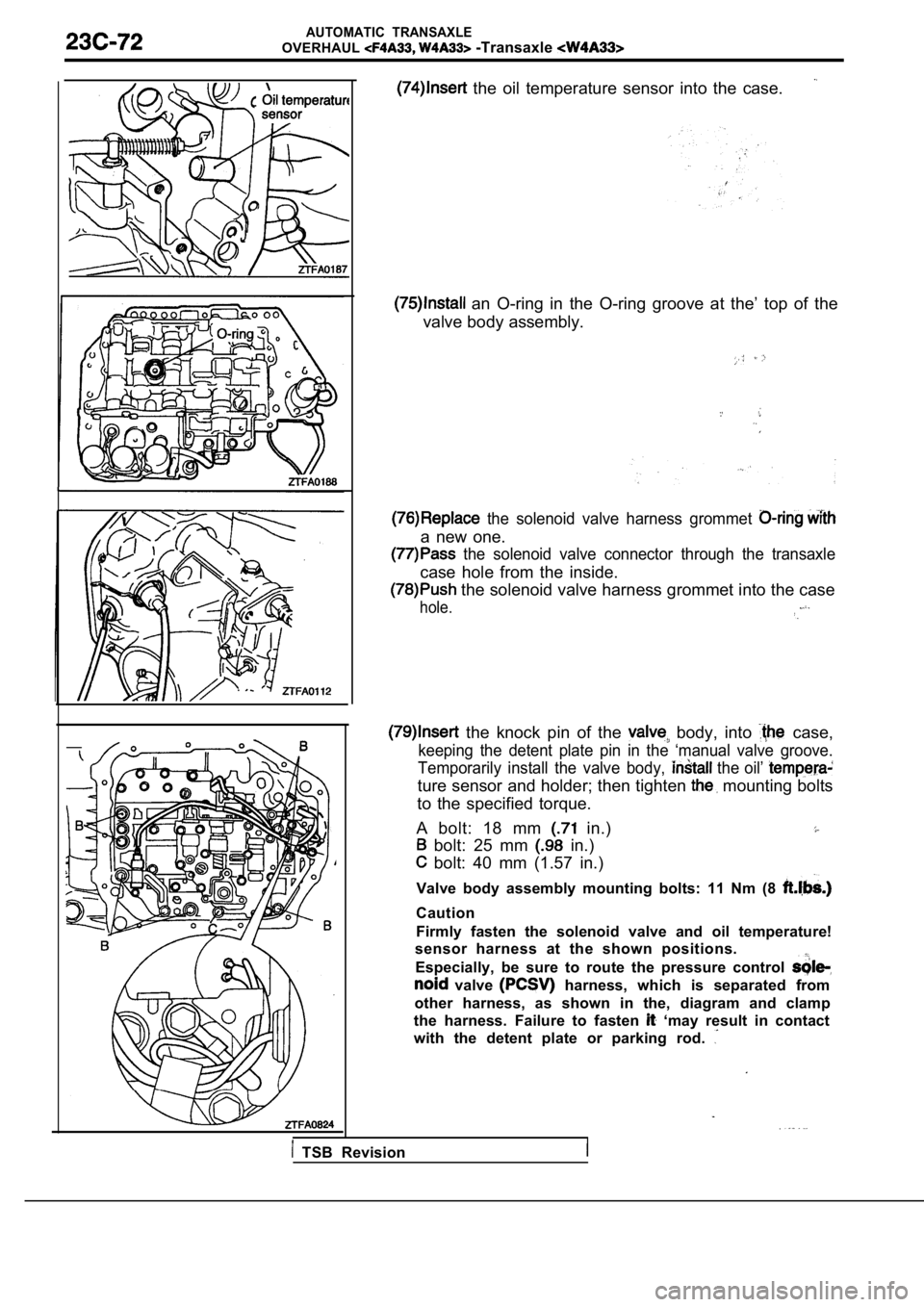
the oil temperature sensor into the case.
an O-ring in the O-ring groove at the’ top of the
valve body assembly.
the solenoid valve harness grommet
a new one.
the solenoid valve connector through the transaxle
case hole from the inside.
the solenoid valve harness grommet into the case
hole.
the knock pin of the body, into case,
keeping the detent plate pin in the ‘manual valve g roove.
Temporarily install the valve body,
the oil’
ture sensor and holder; then tighten mounting bolts
to the specified torque.
A bolt: 18 mm
in.)
bolt: 25 mm in.)
bolt: 40 mm (1.57 in.)
Valve body assembly mounting bolts: 11 Nm (8
Caution
Firmly fasten the solenoid valve and oil temperatur e!
sensor harness at the shown positions.
Especially, be sure to route the pressure control
valve harness, which is separated from
other harness, as shown in the, diagram and clamp
the harness. Failure to fasten
‘may result in contact
with the detent plate or parking rod.
TSB Revision
Page 1404 of 2103
AUTOMATIC TRANSAXLE OVERHAUL General Information
G E N E R A L I N F O R M A T I O N
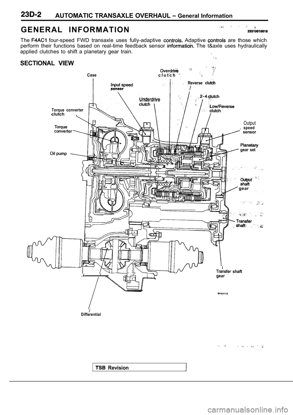
The four-speed FWD transaxle uses fully-adaptive Adaptive are those which
perform their functions based on real-time feedback sensor
The t&axle uses hydraulically
applied clutches to shift a planetary gear train.
SECTIONAL VIEW
Casec l u t c h
sensor
Torque converterclutch ,
Reverse
Outputspeed sensor
gear set
Revision
gear
shaftgear
Differential
Page 1417 of 2103
AUTOMATIC TRANSAXLE OVERHAUL Transaxle
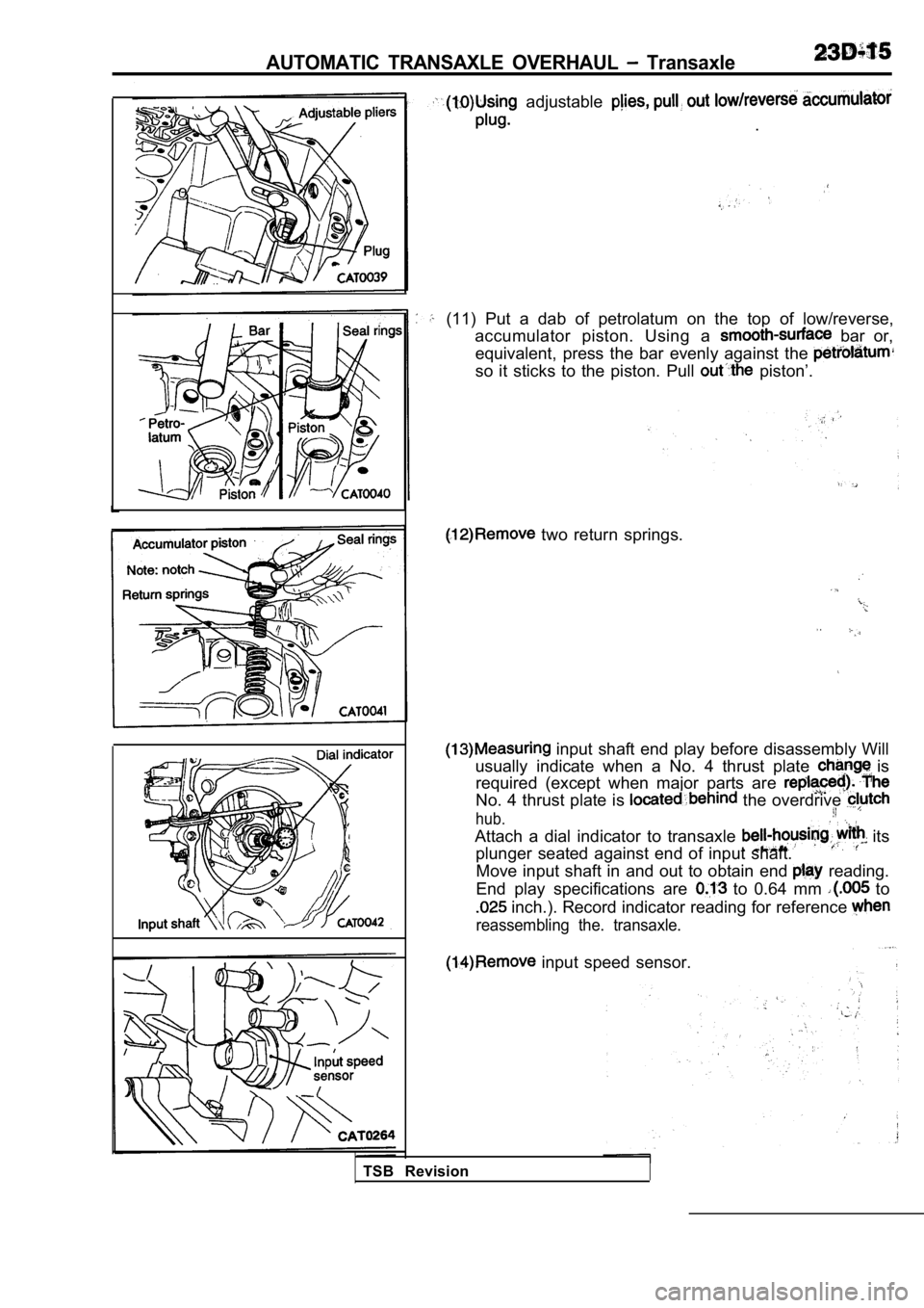
adjustable
.
(11) Put a dab of petrolatum on the top of low/reve rse,
accumulator piston. Using a
bar or,
equivalent, press the bar evenly against the
so it sticks to the piston. Pull piston’.
two return springs.
input shaft end play before disassembly Will
usually indicate when a No. 4 thrust plate
is
required (except when major parts are
No. 4 thrust plate is the overdrive
hub.
Attach a dial indicator to transaxle its
plunger seated against end of input shaft.
Move input shaft in and out to obtain end
reading.
End play specifications are
to 0.64 mm to
inch.). Record indicator reading for reference
reassembling the. transaxle.
input speed sensor.
TSB Revision
Page 1446 of 2103
AUTOMATIC TRANSAXLE OVERHAUL Transaxle
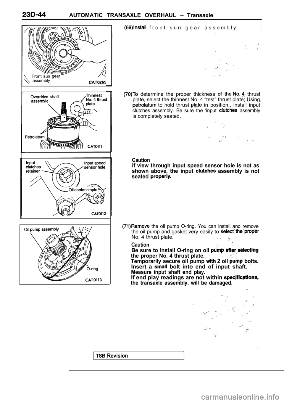
f r o n t s u n g e a r a s s e m b l y .
Front sun assembly
shaft
Oil
determine the proper thickness thrust
plate, select the thinnest No. 4 “test” thrust plat e; Using,
to hold thrust in position,, install input
clutches assembly. Be sure the ‘input assembly
is completely seated.
Caution
if view through input speed sensor hole is not as
shown above, the input
assembly is not
seated
the oil pump O-ring. You can install and remove
the oil pump and gasket very easily to
No. 4 thrust plate..Caution
Be sure to install O-ring on oil
the proper No. 4 thrust plate.
Temporarily secure oil pump 2 oil bolts.
Insert a bolt into end of input shaft.
Measure input shaft end play.
If end play readings are not within
the transaxle assembly. will be damaged.
.
TSBRevision
Page 1467 of 2103
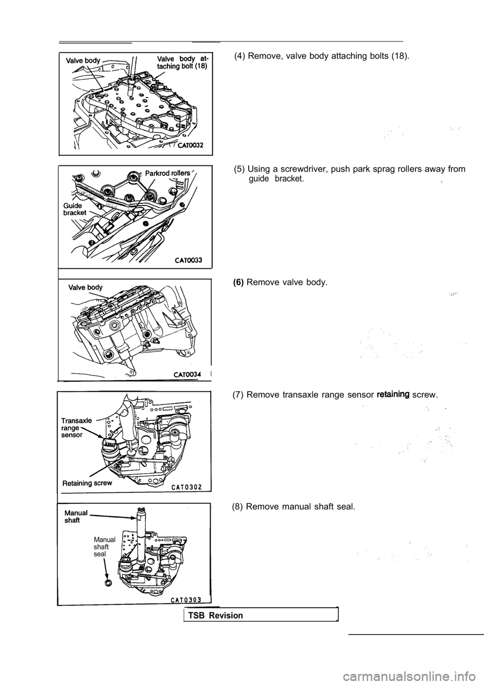
(4) Remove, valve body attaching bolts (18).
I
Manual
shaft
seal
(5) Using a screwdriver, push park sprag rollers aw ay from
guide bracket.
(6)Remove valve body.
(7) Remove transaxle range sensor
screw.
(8) Remove manual shaft seal.
TSB Revision