sensor MITSUBISHI SPYDER 1990 Service Repair Manual
[x] Cancel search | Manufacturer: MITSUBISHI, Model Year: 1990, Model line: SPYDER, Model: MITSUBISHI SPYDER 1990Pages: 2103, PDF Size: 68.98 MB
Page 1727 of 2103
ABS Wheel
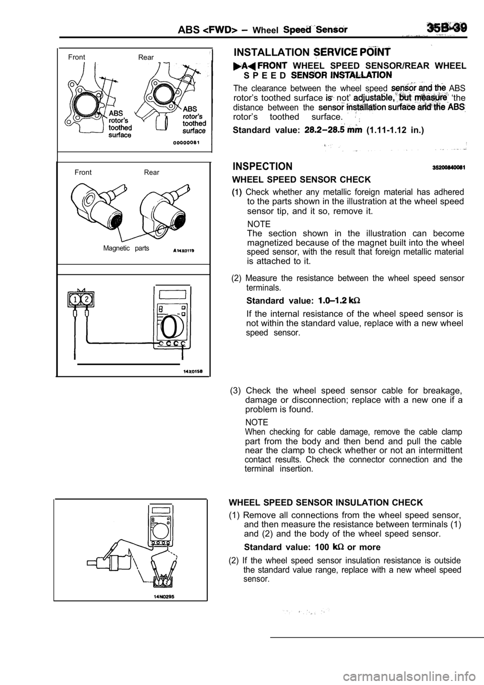
INSTALLATIONFrontRear
FrontRear
Magnetic parts
0 C C
WHEEL SPEED SENSOR/REAR WHEEL
S P E E D
The clearance between the wheel speed ABS
rotor’s toothed surface not’ ‘the
distance between the
rotor’s toothed surface.
Standard value: (1.11-1.12 in.)
INSPECTION
WHEEL SPEED SENSOR CHECK
Check whether any metallic foreign material has ad hered
to the parts shown in the illustration at the wheel speed
sensor tip, and it so, remove it.
NOTE
The section shown in the illustration can become magnetized because of the magnet built into the whe el
speed sensor, with the result that foreign metallic material
is attached to it.
(2) Measure the resistance between the wheel speed sensor
terminals.
Standard value:
If the internal resistance of the wheel speed sensor is
not within the standard value, replace with a new w heel
speed sensor.
(3) Check the wheel speed sensor cable for breakage ,
damage or disconnection; replace with a new one if a
problem is found.
NOTE
When checking for cable damage, remove the cable cl amp
part from the body and then bend and pull the cable
near the clamp to check whether or not an intermittent
contact results. Check the connector connection and the
terminal insertion.
WHEEL SPEED SENSOR INSULATION CHECK
(1) Remove all connections from the wheel speed sen sor,
and then measure the resistance between terminals ( 1)
and (2) and the body of the wheel speed sensor.
Standard value: 100
or more
(2) If the wheel speed sensor insulation resistance is outside
the standard value range, replace with a new wheel speed
sensor.
Page 1731 of 2103
CONTENTS
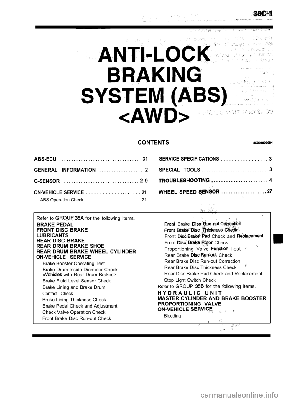
ABS-ECU. . . . . . . . . . . . . . . . . . . . . . . . . . . . . . . . .31 SERVICE SPECIFICATIONS . . . . . . . . . . . . . . . . . 3
GENERAL INFORMATION2SPECIAL TOOLS. . . . . . . . . . . . . . . . . . . . . . . . . . .3. . . . . . . . . . . . . . . . . .
G-SENSOR2 9. . . . . . . . . . . . . . . . . . . . . . . . . . . . . . .4
ON-VEHICLE SERVICE . . . . . . . . . . . .
. . . . 21WHEEL SPEED . . . . . . . . . . . . . . . . . .
ABS Operation Check . . . . . . . . . . . . . . . . . . . . . . . 21
Refer to for the following items.
BRAKE PEDAL
FRONT DISC BRAKE
LUBRICANTS
REAR DISC BRAKE
REAR DRUM BRAKE SHOE
REAR DRUM BRAKE WHEEL CYLINDER
ON-VEHICLE SERVICE
Brake Booster Operating Test
Brake Drum Inside Diameter Check
with Rear Drum Brakes>
Brake Fluid Level Sensor Check
Brake Lining and Brake Drum
Contact Check
Brake Lining Thickness Check Brake Pedal Check and Adjustment
Check Valve Operation Check
Front Brake Disc Run-out Check
Brake
Front Check and
Front Check
Proportioning Valve Test
Rear Brake Check
Rear Brake Disc Run-out Correction
Rear Brake Disc Thickness Check
Rear Disc Brake Pad Check and Replacement
Stop Light Switch Check
Refer to GROUP for the following items.
H Y D R A U L I C U N I T
MASTER CYLINDER AND BRAKE BOOSTER
PROPORTIONING VALVE
ON-VEHICLE
,
Bleeding,
Page 1732 of 2103
ABS General Information
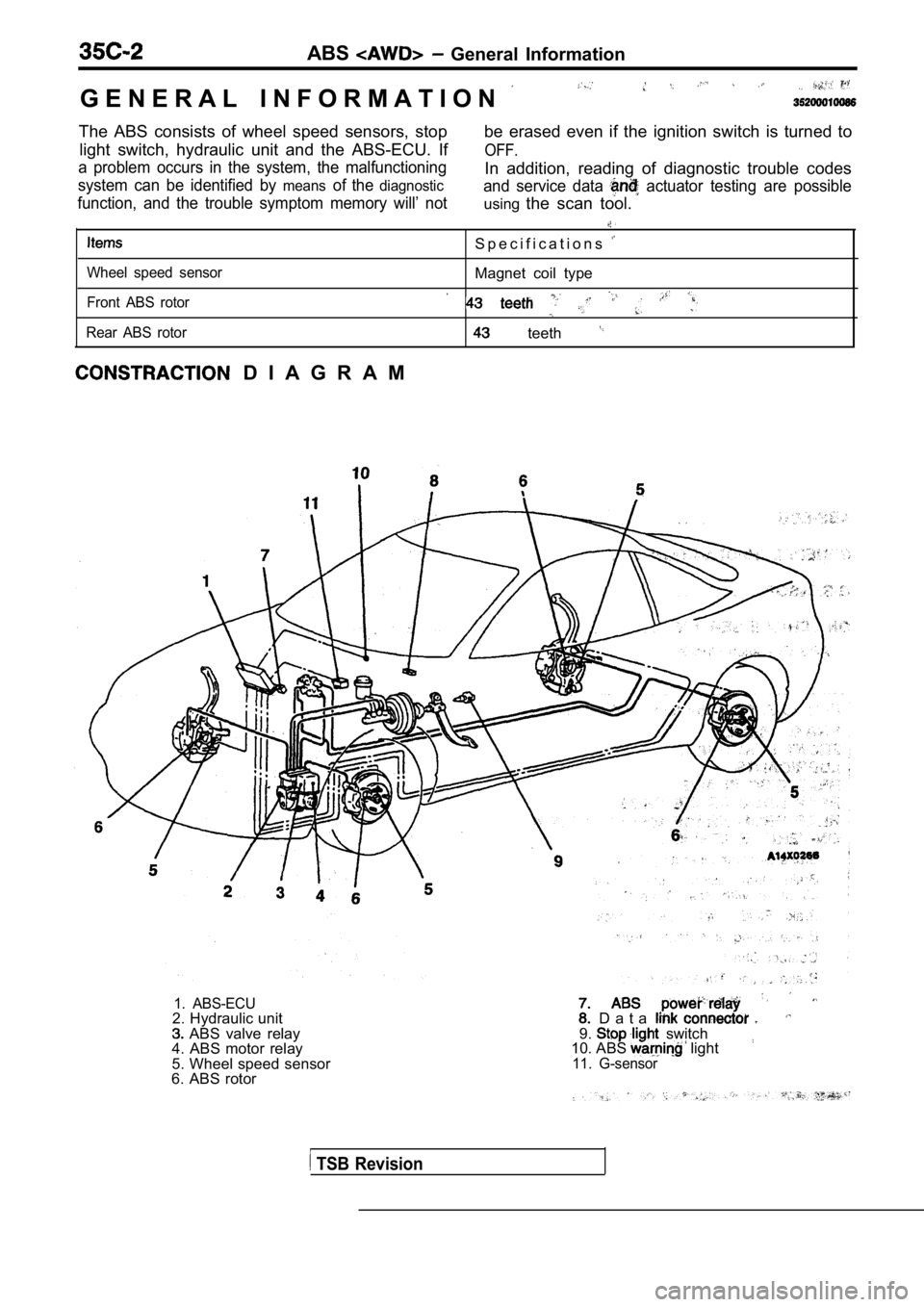
G E N E R A L I N F O R M A T I O N
The ABS consists of wheel speed sensors, stop light switch, hydraulic unit and the ABS-ECU. If be erased even if the ignition switch is turned to
OFF.
a problem occurs in the system, the malfunctioning
system can be identified by
meansof the diagnostic
In addition, reading of diagnostic trouble codes
function, and the trouble symptom memory will’ not and service data
actuator testing are possible
using
the scan tool.
S p e c i f i c a t i o n s
Wheel speed sensorMagnet coil type
Front ABS rotor
Rear ABS rotor teeth
D I A G R A M
1. ABS-ECU2. Hydraulic unit ABS valve relay
4. ABS motor relay
5. Wheel speed sensor
6. ABS rotor D a t a 9. switch
10. ABS light11. G-sensor
TSB Revision
Page 1733 of 2103
A B S Service Tools
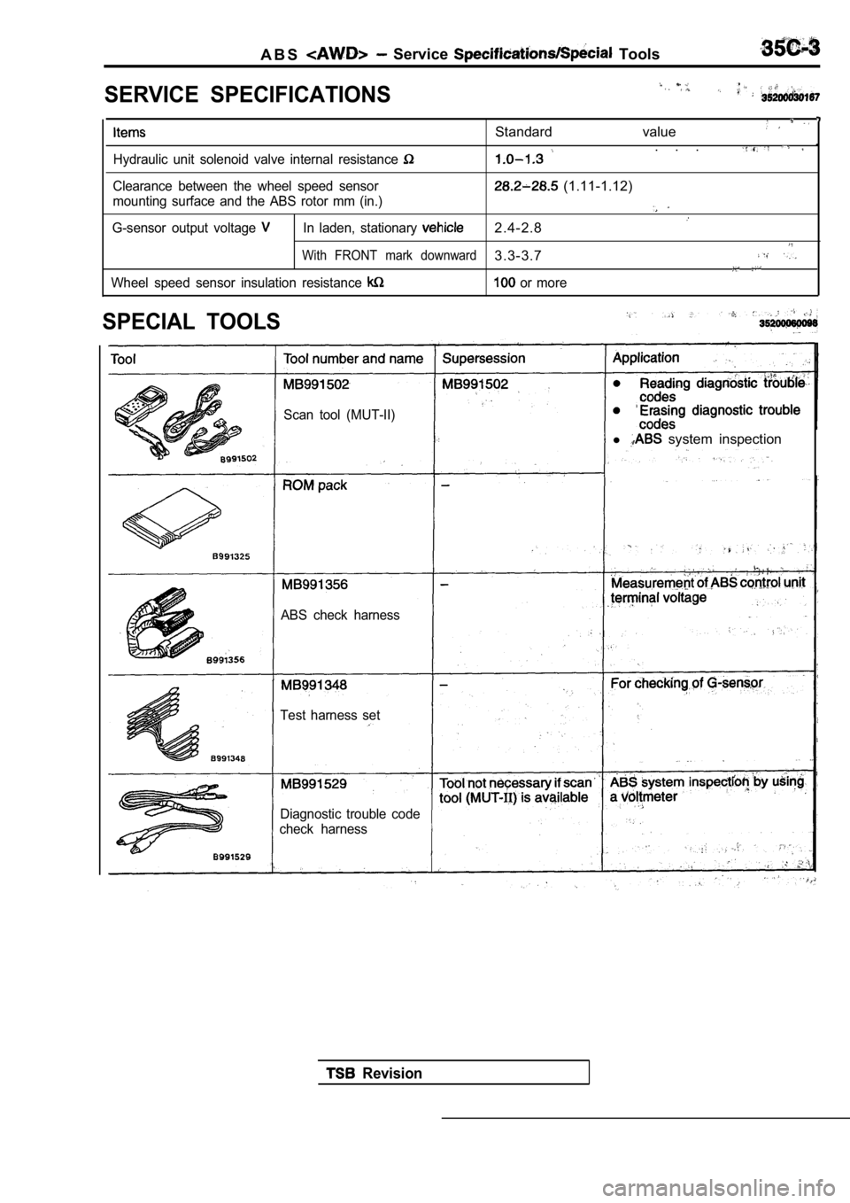
SERVICE SPECIFICATIONS
Standard value
. . .Hydraulic unit solenoid valve internal resistance
Clearance between the wheel speed sensor (1.11-1.12)
mounting surface and the ABS rotor mm (in.)
G-sensor output voltage In laden, stationary 2.4-2.8
With FRONT mark downward3.3-3.7
Wheel speed sensor insulation resistance or more
SPECIAL TOOLS
Scan tool (MUT-II)
l system inspection
ABS check harness
Test harness set
Diagnostic trouble code
check harness
Revision
Page 1736 of 2103
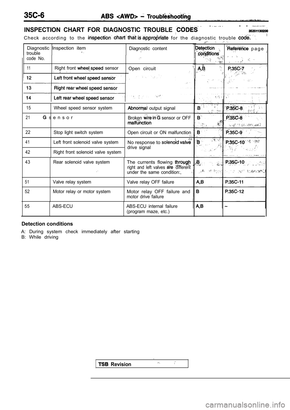
INSPECTION CHART FOR DIAGNOSTIC TROUBLE
.. .
C h e c k a c c o r d i n g t o t h e f o r t h e d i a g n o s t i c t r o u b l e
Diagnostic Inspection item
troubleDiagnostic content. p a g e
code No. .
,
11Right front sensorOpen circuit
.,
15Wheel speed sensor system
21 s e n s o r
output signal
Broken
sensor or OFF
22
41
42
Stop light switch system Open circuit or ON malfunction
Left front solenoid valve systemNo response to
Right front solenoid valve systemdrive signal
43
51
52
Rear solenoid valve system
Valve relay system
Motor relay or motor system
The currents flowing
right and left valves different
under the same condition:,
Valve relay OFF failure
Motor relay OFF failure and
motor drive failure
55ABS-ECU ABS-ECU internal failure
(program maze, etc.)
Detection conditions
A: During system check immediately after starting B: While driving
Revision
Page 1737 of 2103
![MITSUBISHI SPYDER 1990 Service Repair Manual INSPECTION PROCEDURE CLASSIFIED BY DIAGNOSTIC TROUBLE
Code No. Wheel speed sensor open circuitProbable cause
[Comment]The ABS-ECU detects breaks in the wheel speed senso
r wire. MITSUBISHI SPYDER 1990 Service Repair Manual INSPECTION PROCEDURE CLASSIFIED BY DIAGNOSTIC TROUBLE
Code No. Wheel speed sensor open circuitProbable cause
[Comment]The ABS-ECU detects breaks in the wheel speed senso
r wire.](/img/19/57345/w960_57345-1736.png)
INSPECTION PROCEDURE CLASSIFIED BY DIAGNOSTIC TROUBLE
Code No. Wheel speed sensor open circuitProbable cause
[Comment]The ABS-ECU detects breaks in the wheel speed senso
r wire. o f w h e e l S p e e d Malfunction of wiring harness l Malfunction of ABS-ECU
,
lDisconnect the connector and mea-
sure at the harness side.
l Resistance value between terminals
a n d O KCheck trouble symptom.each wheel speed sensor and the
Wheel speed sensor check(Refer to GROUP -Wheel Sensor Check.)
Replace the wheel speed sensor.
IOKN GABS rotor check (Refer to Replace the ABS rotor.
Refer to GROUP 26 On-vehicle
Refer to GROUP 27
On-vehicle
Check the
connector: N G
l Repair
OK
1
Check trouble symptom. Replace the ABS-ECU.
1
TSB Revision
,
Page 1738 of 2103
![MITSUBISHI SPYDER 1990 Service Repair Manual Code No. 15 Wheel sensor svstem
[Comment] of . This diagnostic trouble code is output when there is an abnormality (other than brokenwire or short circuit) in any of the MITSUBISHI SPYDER 1990 Service Repair Manual Code No. 15 Wheel sensor svstem
[Comment] of . This diagnostic trouble code is output when there is an abnormality (other than brokenwire or short circuit) in any of the](/img/19/57345/w960_57345-1737.png)
Code No. 15 Wheel sensor svstem
[Comment] of . This diagnostic trouble code is output when there is an abnormality (other than brokenwire or short circuit) in any of the wheel speed sensor output signals while driving.l
Malfunction of harness
The following can be considered as the cause of the wheel speed sensor outputl
Malfunction of ABS rotor
l
wheel abnormality.l Malfunction of ABS-ECU
l Distortion of ABS rotor, teeth missing
l Low frequency noise interference when sensor harnes s is broken
l Noise interference in sensor signal
,lSensor output signal is below the standard value or amplitude modulation is over
the standard value. Using an oscilloscope to measur e the wave shape of the
wheel speed sensor output signal is very effective.
l Broken sensor harness
Poor connection of connector
I-NGWheel speed sensor insulation check Repair
(Refer to
OK
(Refer to(Refer to GROUP -Wheel Speed
Refer to 28 On-vehicleService.Refer to GROUP 27 On-vehicle wheel speed sensors and the
ABS-ECU. Repair, if necessary.
Check the following connector: l
OK
Check trouble symptom.
NG
the ABS-ECU.
Service.
NG Repair
,
Code No. 21 G-sensor systemProbable cause
[Comment]l Malfunction of G-sensor
The ABS-ECU outputs this diagnostic trouble code in the following cases.
l Malfunction of wiring harness or connector
lWhen there is an open or short circuit in the harne ss for the G-sensor system.
l Malfunction of ABS-ECU
G-sensor check (Refer to
Replace the G-sensor.
Measure at ABS-ECU connector
l Ignition switch ONlVoltage between terminal 8 and bodygroundOK 2.4-2.6 Check the harness between theOKCheck trouble symptom.G-sensor and the ABS-ECU. Repair,
NGif necessary.Check the following connector:
. Repair
OK
Check trouble symptom.
N G
Replace the ABS-ECU.
Page 1747 of 2103
![MITSUBISHI SPYDER 1990 Service Repair Manual , , .
PROCEDURE 7
Break operation is
[Comment] o f w h e e l This depending on the driving conditions and the road surface conditions, so ‘ M a l f u n c t i o n _ _
problem diagno MITSUBISHI SPYDER 1990 Service Repair Manual , , .
PROCEDURE 7
Break operation is
[Comment] o f w h e e l This depending on the driving conditions and the road surface conditions, so ‘ M a l f u n c t i o n _ _
problem diagno](/img/19/57345/w960_57345-1746.png)
, , .
PROCEDURE 7
Break operation is
[Comment] o f w h e e l This depending on the driving conditions and the road surface conditions, so ‘ M a l f u n c t i o n _ _
problem diagnosis is difficult. However, if a normal diagnostic trouble code is displayed,l
carry out the following Malfunction of bearing. . .l of: .
W h e e l s p e e d -NG: Repair(Refer to
N G N G speed sensor check(Refer to GROUP -Wheel SpeedReplace the wheel speed sensor.
OKSensor Check.)
OK
Hydraulic unit check (Refer to N GABS rotor check (Refer to Replace the rotor.
OK
Wheel bearing end play check
Refer to GROUP 26 On-vehicle Repair
Refer to GROUP 27
On-vehide
Service.
Check trouble symptom.
N G
ABS-ECU connector Disconnect the connector and measure at the harness side.
Resistance value between termi-nals and
NG Repair
O K
The sensor harness and connector s h o u l d b e m o v e d w h i l e t h e s e
inspections are carried out.
the .
TSB Revision
Page 1748 of 2103
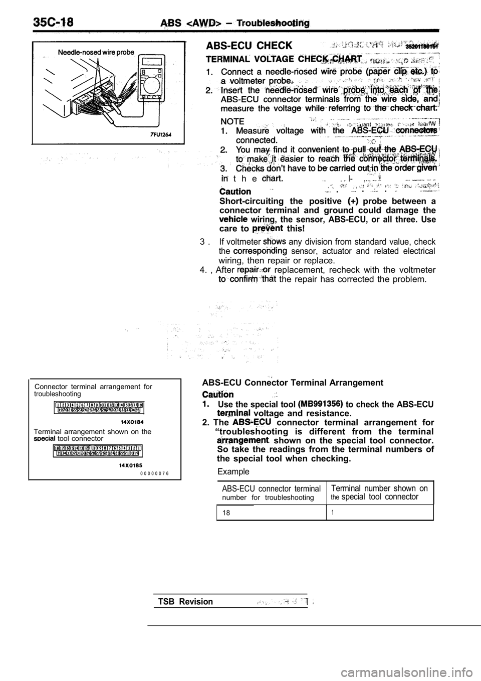
t h e . I-,..,
.. .
Short-circuiting the positive probe between a
connector terminal and ground could damage the
wiring, the sensor, ABS-ECU, or all three. Use
care to this!
3 .
If voltmeter any division from standard value, check
the
sensor, actuator and related electrical
wiring, then repair or replace.
4. , After
replacement, recheck with the voltmeter
the repair has corrected the problem.
Connector terminal arrangement for
troubleshooting
Terminal arrangement shown on the tool connector
0 0 0 0 0 0 7 6 ABS-ECU Connector Terminal Arrangement
Use the special tool to check the ABS-ECU
voltage and resistance.
2. The
connector terminal arrangement for
“troubleshooting is different from the terminal
shown on the special tool connector.
So take the readings from the terminal numbers of
the special tool when checking.
Example
ABS-ECU connector terminalTerminal number shown on
number for troubleshootingthespecial tool connector
181
TSB Revision
Page 1749 of 2103
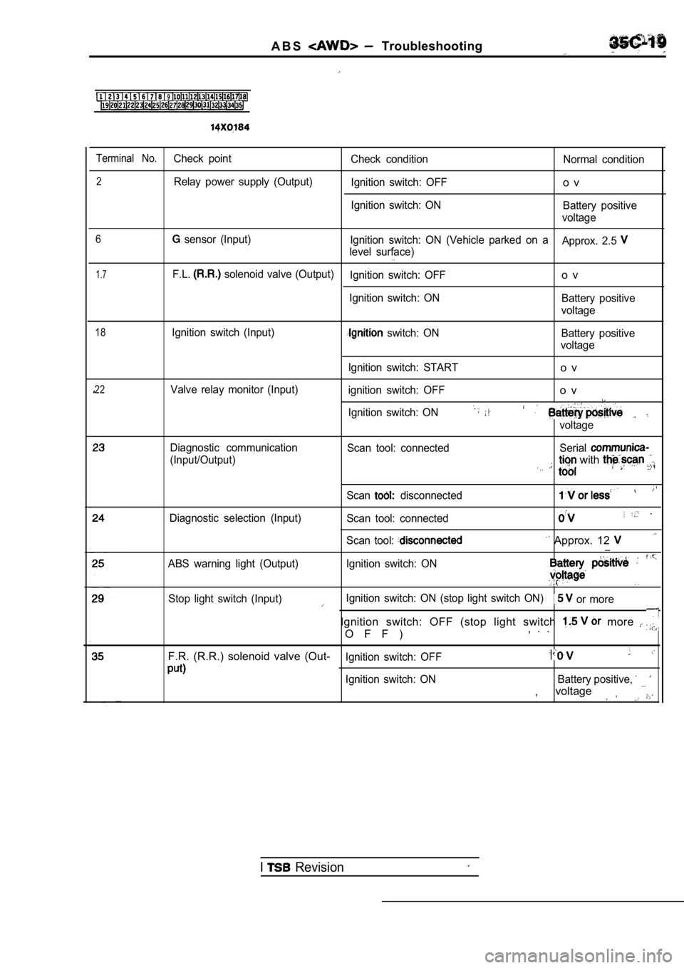
A B S Troubleshooting
9
Terminal No.Check pointCheck condition Normal condition
2Relay power supply (Output)
Ignition switch: OFFo v
Ignition switch: ON Battery positive
voltage
6
1.7
sensor (Input) Ignition switch: ON (Vehicle parked on a
Approx. 2.5
level surface). .
F.L. solenoid valve (Output)Ignition switch: OFFo v
Ignition switch: ON Battery positive
voltage
18Ignition switch (Input) switch: ON Battery positive
voltage
22Valve relay monitor (Input) Ignition switch: START
o v
ignition switch: OFFo v
Ignition switch: ON
voltage
Diagnostic communication
(Input/Output)
Scan tool: connected Serial
with
Scan disconnected
Diagnostic selection (Input)
Scan tool: connected .
Scan tool: Approx. 12 __
ABS warning light (Output) Ignition switch: ON
Stop light switch (Input)Ignition switch: ON (stop light switch ON) or more
Ignition switch: OFF (stop light switch more
O F F ), . .
F.R. (R.R.) solenoid valve (Out-
Ignition switch: OFF
Ignition switch: ON Battery positive,
voltage
I Revision