check oil MITSUBISHI SPYDER 1990 Service Service Manual
[x] Cancel search | Manufacturer: MITSUBISHI, Model Year: 1990, Model line: SPYDER, Model: MITSUBISHI SPYDER 1990Pages: 2103, PDF Size: 68.98 MB
Page 228 of 2103
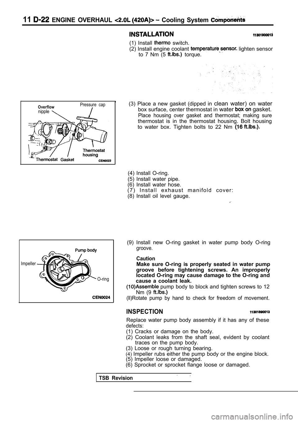
11 ENGINE OVERHAUL Cooling System
(1) Install switch.
(2) Install engine coolant
lighten sensor
to 7 Nm (5
torque.
Overflownipple
Pressure cap
Impeller
TSB Revision
O-ring
(3) Place a new gasket (dipped in clean water) on water
box surface, center thermostat in water
gasket.
Place housing over gasket and thermostat; making su re
thermostat is in the thermostat housing. Bolt housing
to water box. Tighten bolts to 22 Nm
(4) Install O-ring.
(5) Install water pipe.
(6) Install water hose.
( 7 ) I n s t a l l e x h a u s t m a n i f o l d c o v e r :
(8) Install oil level gauge.
(9) Install new O-ring gasket in water pump body O- ring
groove.
Caution
Make sure O-ring is properly seated in water pump
groove before tightening screws. An improperly
located O-ring may cause damage to the O-ring and
cause a coolant leak.
pump body to block and tighten screws to 12
Nm (9
(ll)Rotate pump by hand to check for freedom of mov ement.
INSPECTION
Replace water pump body assembly if it has any of these
defects:
(1) Cracks or damage on the body.
(2) Coolant leaks from the shaft seal, evident by c oolant
traces on the pump body.
(3) Loose or rough turning bearing.
(4) Impeller rubs either the pump body or the engine bl ock.
(5) Impeller loose or damaged.
(6) Sprocket or sprocket flange loose or damaged.
Page 237 of 2103
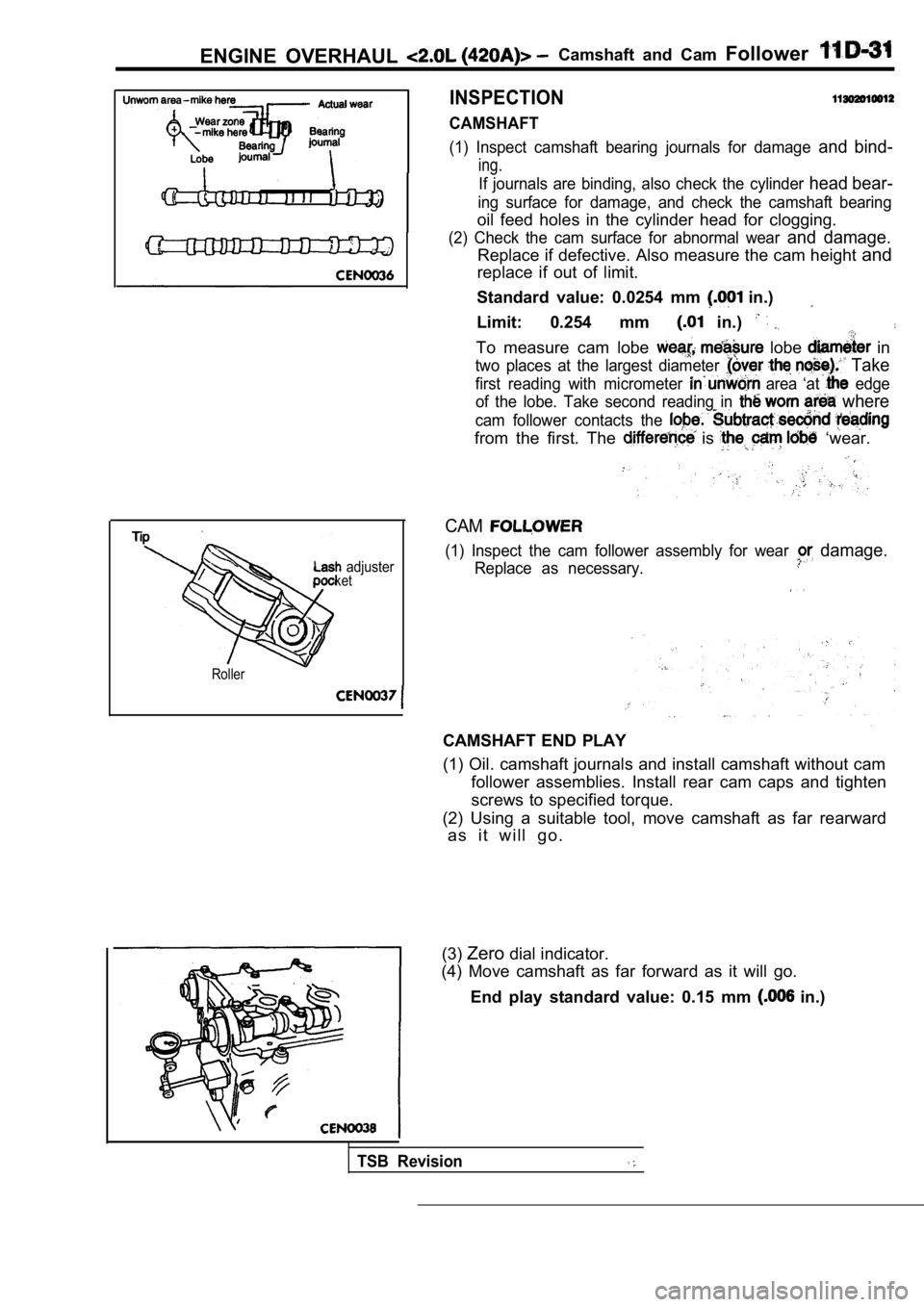
(1) Inspect camshaft bearing journals for damage and bind-
ing.
If journals are binding, also check the cylinder head bear-
ing surface for damage, and check the camshaft bearing
oil feed holes in the cylinder head for clogging.
(2) Check the cam surface for abnormal wear and damage.
Replace if defective. Also measure the cam height and
replace if out of limit.
Standard value: 0.0254 mm
in.)
Limit: 0.254 mm in.)
To measure cam lobe lobe in
two places at the largest diameter Take
first reading with micrometer area ‘at edge
of the lobe. Take second reading in
where
cam follower contacts the
from the first. The is ‘wear.
ENGINE OVERHAUL Camshaft and Cam Follower
INSPECTION
CAMSHAFT
adjusterket
Roller
CAM
(1) Inspect the cam follower assembly for wear damage.
Replace as necessary.
CAMSHAFT END PLAY
(1) Oil. camshaft journals and install camshaft wit hout cam
follower assemblies. Install rear cam caps and tigh ten
screws to specified torque.
(2) Using a suitable tool, move camshaft as far rea rward
a s i t w i l l g o .
(3) Zero dial indicator.
(4) Move camshaft as far forward as it will go.
End play standard value: 0.15 mm
in.)
TSB Revision
Page 257 of 2103
Rod
a n d
(8) Install each bolt finger tight then alternately torque each
nut to. assemble the cap properly.
(9) Tighten the bolts to 27.0 Nm PLUS turn (20
PLUS turn). Do not use a torque wrench for last
step.
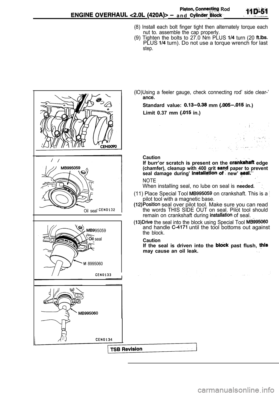
Oil seal
95059
seal
8995060
I
(lO)Using a feeler gauge, check connecting rod’ sid e clear-’
Standard value: mm in.)
Limit 0.37 mm
in.)
Caution
If burr’or scratch is present on the edge
(chamfer), cleanup with 400 grit paper to prevent
seal damage during’
new’
NOTE
When installing seal, no lube on seal is needed.
(11) Place Special Tool on crankshaft. This is a
pilot tool with a magnetic base.
seal over pilot tool. Make sure you can read
the words THIS SIDE OUT on seal. Pilot tool should
remain on crankshaft during
of seal.
the seal into the block using Special Tool
and handle until the tool bottoms out against
the block.
Caution
If the seal is driven into the past flush,
may cause an oil leak.
Page 259 of 2103
Piston,
E N G I N E
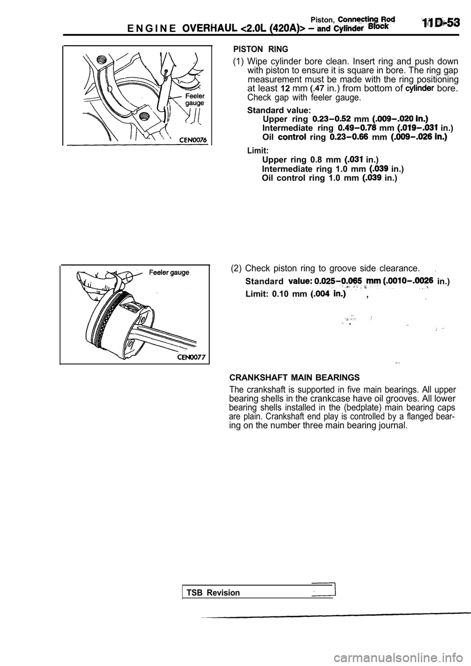
PISTON RING
(1) Wipe cylinder bore clean. Insert ring and push down
with piston to ensure it is square in bore. The rin g gap
measurement must be made with the ring positioning
at least 12mm in.) from bottom of bore.
Check gap with feeler gauge.
Standard value:
Upper ring
mm
Intermediate ring mm in.)
Oil
ring mm
Limit:
Upper ring 0.8 mm in.)
Intermediate ring 1.0 mm
in.)
Oil control ring 1.0 mm
in.)
(2) Check piston ring to groove side clearance..
Standard in.)
Limit: 0.10 mm
,
.
CRANKSHAFT MAIN BEARINGS
The crankshaft is supported in five main bearings. All upper
bearing shells in the crankcase have oil grooves. All lower
bearing shells installed in the (bedplate) main bea ring caps
are plain. Crankshaft end play is controlled by a flanged bear-
ing on the number three main bearing journal.
TSB Revision
Page 266 of 2103
11E N G I N E. .
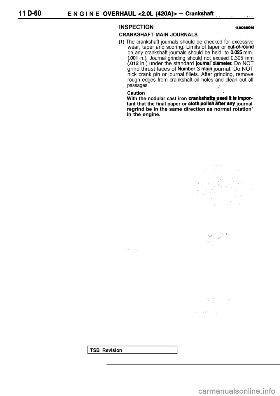
INSPECTION
CRANKSHAFT MAIN JOURNALS
The crankshaft journals should be checked for excessive
wear, taper and scoring. Limits of taper or
on any crankshaft journals should be held. to mm.
in.). Journal grinding should not exceed 0.305 mm
in.) under the standard Do NOT
grind thrust faces of 3 journal. Do NOT
nick crank pin or journal fillets. After grinding, remove
rough edges from crankshaft oil holes and clean out all
passages.,
Caution.
With the nodular cast iron
tant that the final paper or journal
regrind be in the same direction as normal rotation’
in the engine.
TSB Revision
Page 267 of 2103
ENGINE
BEARING CLEARANCE
(1) The. total: clearance of the main bearings can only be
determined by removing the weight of the crankshaft .
This is accomplished by having the engine turned upside
down on the engine stand. This will remove all the crank-
weight off the bearing surface.
(2) Place, a piece of Plastigage across the entire width of
the bearing shell in the approximately 6.35 mm
in.) off center and away from the oil holes. In addition,
suspect areas can be checked by placing the Plastig age
in the suspect area.
Torque the
bolts of the bearing being checked
to the proper specifications.
Caution
Do not rotate crankshaft, or the Plastigage may be
smeared.
(3) Remove the and compare the width of the flat-
tened Plastigage with the metric scale provided on the
package.
Standard value: mm in.)
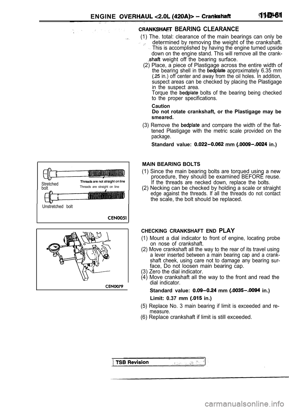
Stretched
boltThreads are straight on line,
Unstretched bolt
MAIN BEARING BOLTS
(1) Since the main bearing bolts are torqued using a new
procedure, they should be examined BEFORE reuse.
If the threads are necked down, replace the bolts.
(2) Necking can be checked by holding a scale or st raight
edge against the threads. If all the threads do not contact
the scale, the bolt should be replaced.
CHECKING CRANKSHAFT END PLAY
(1) Mount a dial indicator to front of engine, locating probe
on nose of crankshaft.
(2) Move crankshaft all the way to the rear of its travel using
a lever inserted between a main bearing cap and a c rank-
shaft cheek, using care not to damage any bearing sur-
face, Do not loosen main bearing cap.
(3) Zero the dial indicator.
(4) Move crankshaft all the way to the front and re ad the
dial indicator.
Standard value: mm in.)
Limit: 0.37 mm
in.)
(5) Replace No. 3 main bearing if limit is exceeded and re-
measure.
(6) Replace crankshaft if limit is still exceeded.
Page 269 of 2103
CONTENTS
CAMSHAFT AND CAMSHAFT OILCompression Pressure Check. . . . . . . . . . ..
SEAL. . . . . . . . . . . . . . . . . . . . . . . . . . . . . . . . . . . . .21Curb Speed Check. . ... . . . .. . . . . . . . .
Drive Belt Tension Check and
CRANKSHAFT FRONT OIL SEAL. . . . . . . . . .26Adjustment.. . . . . . . . . . . . . . . . . . . . . . . . . . . .
Mixture Check . . . . . . . . . . . . . . . . . . . . . . .
CRANKSHAFT PULLEY. . . . . . . . . . . . . . . . . . .20Ignition Timing Check
. . . . . . . . . . . . . . . . . . . . . .
. . . . . . . . . . . . . . . . . . . . .13CRANKSHAFT REAR OIL SEAL27Lash Adjuster Check
. . . . . . . . . . .
Manifold Vacuum Check. . . . . . . . . . . . . . . . . .12
CYLINDER HEAD GASKET . . . . . . . . . . . . . . . .29 . .
SEALANTS. . . . . . . . . . . . . . . . . . . . . . . . . . .. .3
ENGINE ASSEMBLY. . . . . . . . . . . . . . . . . . . . . .15SERVICE. . . . . ... .
.....
.....
GENERAL INFORMATION. . . . . . . . . . . . . . . . . .2SPECIAL TOOLS. . . . . . . . . . . . . . . . . . . . . . . . . . .4
OIL PAN AND OIL SCREEN . . . . . . . . . . . . . . .24
ON-VEHICLE SERVICE. . . . . . . . . . . . . . . . . . . . .7
Basic Speed Adjustment
. . . . . . . . . . . . . . . . . . . . . . . Refer to GROUP
TIMING BELT. . . . . . . . . . . . . . . . . . . . . . . . . . . . .35
BELT . . . . . . . . . . . . . . . . . . . . . . . . . . .39
TROUBLESHOOTING
. . . . . . . . . . . . . . . . . . . . . . . 6
Page 271 of 2103
ENGINEService
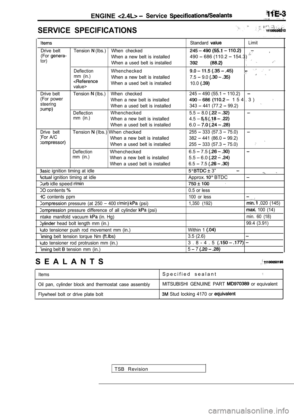
SERVICE SPECIFICATIONS
Drive belt Tension (Ibs.) When checked
(For
When a new belt is installedtor)When a used belt is installed
DeflectionWhenchecked
mm (in.)When a new belt is installed
value> When a used belt is installed
Drive belt Tension
(Ibs.) When checked
(For power When a new belt is installed
steeringWhen a used belt is installed
DeflectionWhenchecked
mm (in.)When a new belt is installed
When a used belt is installed
Drive beltTension (Ibs.) When checked
A/C When a new belt is installed
When a used belt is installed
DeflectionWhenchecked
mm (in.)When a new belt is installed
When a used belt is installed
ignition timing at idle
ignition timing at idle
idle speed
contents
contents ppm
pressure (at 250 400 (psi)
pressure difference of all cylinder (psi)
ntake manifold vacuum
(in. Hg)
head bolt length mm (in.)
tensioner push rod movement mm (in.)
belt tension torque Nm
tensioner rod protrusion mm (in.)
belt tension mm (in.) Standard
Limit
,
490
686 (110.2 154.3)
7.5 9.0
10.0
245 490 (55.1 110.2)
1 5 4 . 3 )
343 441 (77.2 99.2)
5.5 8.0
4.5
6.0
255 333 (57.3 75.0)
382 441 (86.0 99.2)
255
333 (57.3 75.0)
6.5 7.5
5.5 6.0
6.5 7.5
3”
Approx. BTDC
0.5 or less
100 or less
1,350 (192) ,020 (145)
100 (14)
min. 60 (18)
99.4 (3.91)
Within 1
3.5 (2.6)
3 . 8 - 4 . 5
5 7
S E A L A N T S
ItemsS p e c i f i e d s e a l a n t
Oil pan, cylinder block and thermostat case assembl yMITSUBISHI GENUINE PART or equivalent
Flywheel bolt or drive plate bolt
Stud locking 4170 or
TSB Revision
Page 274 of 2103
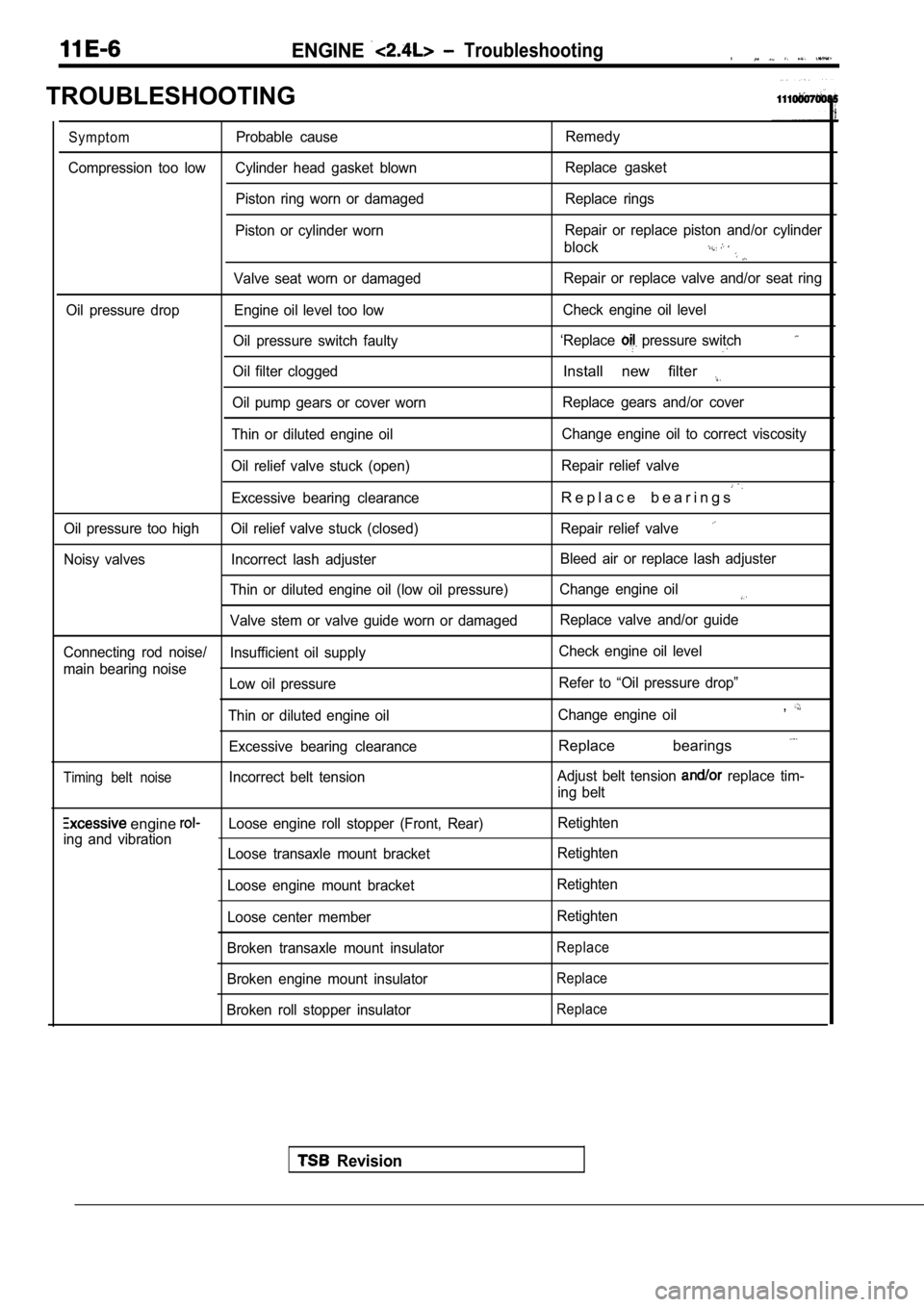
ENGINE Troubleshooting.
TROUBLESHOOTING
SymptomProbable causeRemedy
Compression too low Cylinder head gasket blown Replace gasket
Piston ring worn or damaged Replace rings
Piston or cylinder worn Repair or replace piston and/or cylinder
block
Valve seat worn or damaged Repair or replace valve and/or seat ring
Oil pressure drop Engine oil level too low Check engine oil level
Oil pressure switch faulty ‘Replace
pressure switch
Oil filter cloggedInstall new filter
Oil pump gears or cover worn Replace gears and/or cover
Thin or diluted engine oil Change engine oil to correct viscosity
Oil relief valve stuck (open) Repair relief valve
Excessive bearing clearanceR e p l a c e b e a r i n g s
Oil pressure too high Oil relief valve stuck (closed
) Repair relief valve
Noisy valves Incorrect lash adjuster Bleed air or replace lash adjuster
Thin or diluted engine oil (low oil pressure) Change engine oil
Valve stem or valve guide worn or damaged Replace valve and/or guide
Connecting rod noise/ Insufficient oil supply Check engine oil level
main bearing noise Low oil pressure Refer to “Oil pressure drop”
Thin or diluted engine oil Change engine oil
,
Excessive bearing clearanceReplace bearings
Timing belt noiseIncorrect belt tensionAdjust belt tension replace tim-
ing belt
engine Loose engine roll stopper (Front, Rear) Retighten
ing and vibration Loose transaxle mount bracket Retighten
Loose engine mount bracket Retighten
Loose center member Retighten
Broken transaxle mount insulator
Replace
Broken engine mount insulatorReplace
Broken roll stopper insulatorReplace
Revision
Page 279 of 2103
On-vehicle
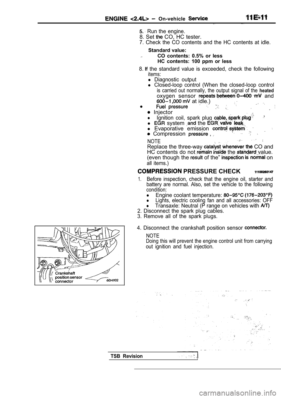
Run the engine.
8. Set CO, HC tester.
7. Check the CO contents and the HC contents at idle.
Standard value:
CO contents: 0.5% or less
HC contents: 100 ppm or less
8. the standard value is exceeded, check the following
items:
l Diagnostic output
l Closed-loop control (When the closed-loop control
is carried out normally, the output signal of the heated
oxygen sensor and
at idle.)
l
Injector
lIgnition coil, spark plug
l system the
l Evaporative emission
Compression ,
NOTE,
Replace the three-way CO and
HC contents do not
the value.
(even though the
of the” on
all items.)
PRESSURE CHECK
1.Before inspection, check that the engine oil, start er and
battery are normal. Also, set the vehicle to the fo llowing
condition:
lEngine coolant temperature:
lLights, electric cooling fan and all accessories: O FF
lTransaxle: Neutral (P range on vehicles with
2. Disconnect the spark plug cables.
3. Remove all of the spark plugs.
4. Disconnect the crankshaft position sensor
NOTE
Doing this will prevent the engine control unit fro m carrying
out ignition and fuel injection.
TSB Revision