check oil MITSUBISHI SPYDER 1990 Service Manual PDF
[x] Cancel search | Manufacturer: MITSUBISHI, Model Year: 1990, Model line: SPYDER, Model: MITSUBISHI SPYDER 1990Pages: 2103, PDF Size: 68.98 MB
Page 346 of 2103
ENGINE OVERHAUL Cylinder Head . .
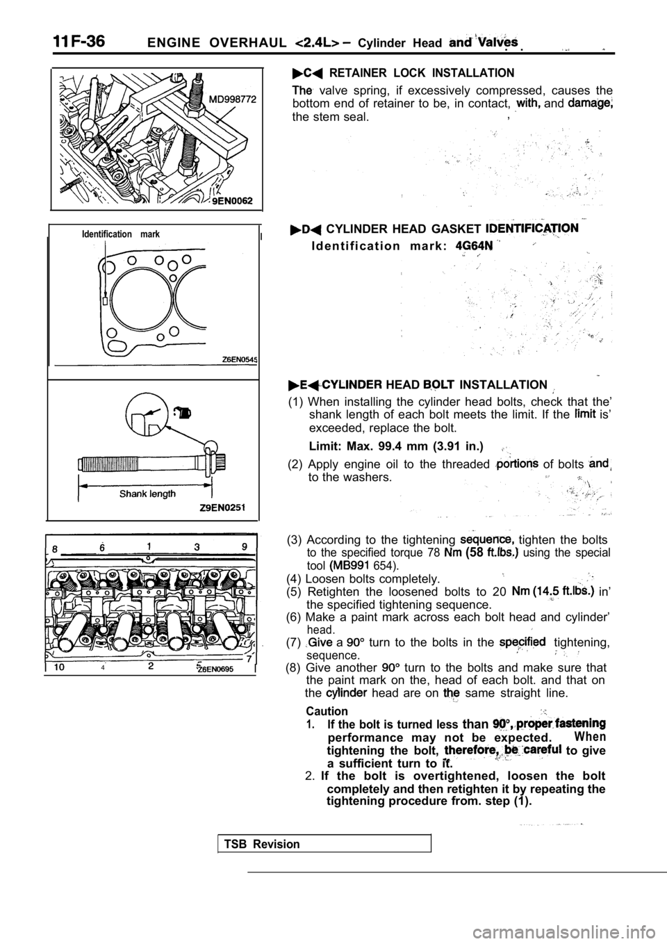
RETAINER LOCK INSTALLATION
valve spring, if excessively compressed, causes the
bottom end of retainer to be, in contact,
and
the stem seal. ,
Identification markI
I4
CYLINDER HEAD GASKET
I d e n t i f i c a t i o n m a r k :
HEAD INSTALLATION
(1) When installing the cylinder head bolts, check
that the’
shank length of each bolt meets the limit. If the
is’
exceeded, replace the bolt.
Limit: Max. 99.4 mm (3.91 in.)
(2) Apply engine oil to the threaded of bolts
to the washers.
(3) According to the tightening tighten the bolts
to the specified torque 78 (58 using the special
tool
654).
(4) Loosen bolts completely.
(5) Retighten the loosened bolts to 20 in’
the specified tightening sequence.
(6) Make a paint mark across each bolt head and cyl inder’
head.
(7) a turn to the bolts in the tightening,
sequence.
(8) Give another turn to the bolts and make sure that
the paint mark on the, head of each bolt. and that on
the
head are on same straight line.
Caution
1.If the bolt is turned less than
performance may not be expected.W h e n
tightening the bolt, to give
a sufficient turn to it.
2. If the bolt is overtightened, loosen the bolt
completely and then retighten it by repeating the
tightening procedure from. step (1).
TSB Revision
Page 357 of 2103
Front
ENGINE OVERHAUL Shaft and
I N S P E C T I O N
FRONT CASE
(1) Check oil holes for clogging and -clean if nece ssary.
(2) Check left counterbalance shaft front bearing
wear, damage and seizure. If there is anything ‘wro ng
with the section, replace the front case.
(3) Check the front case for cracks and other ‘dama ge. Re-
place cracked or damaged front case.
OIL SEAL
(1) Check the oil seal lip for wear and damage. Replace
oil seal if necessary.
(2) Check the
seal lip for deterioration. Replace oil seal
if necessary.
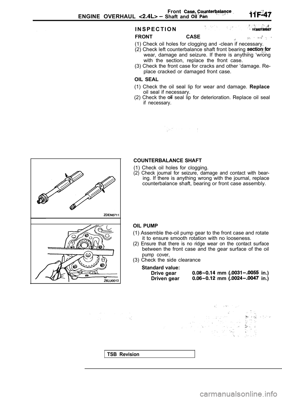
COUNTERBALANCE SHAFT
(1) Check oil holes for clogging.
(2) Check journal for seizure, damage and contact w ith bear-
ing. If there is anything wrong with the journal, replace
counterbalance shaft, bearing or front case assembl y.
OIL PUMP
(1) Assemble the-oil pump gear to the front case an d rotate
it to ensure smooth rotation with no looseness.
(2) Ensure that there is no ridge wear on the conta ct surface
between the front case and the gear surface of the oil
pump cover,
(3) Check the side clearance
Standard value: Drive gear
mm in.)
Driven gear
mm in.)
TSB Revision
Page 361 of 2103
ENGINE OVERHAUL Piston and
Piston pin
Piston pin
Front mark
Stop Lock nut
Connecting rod
guide pin
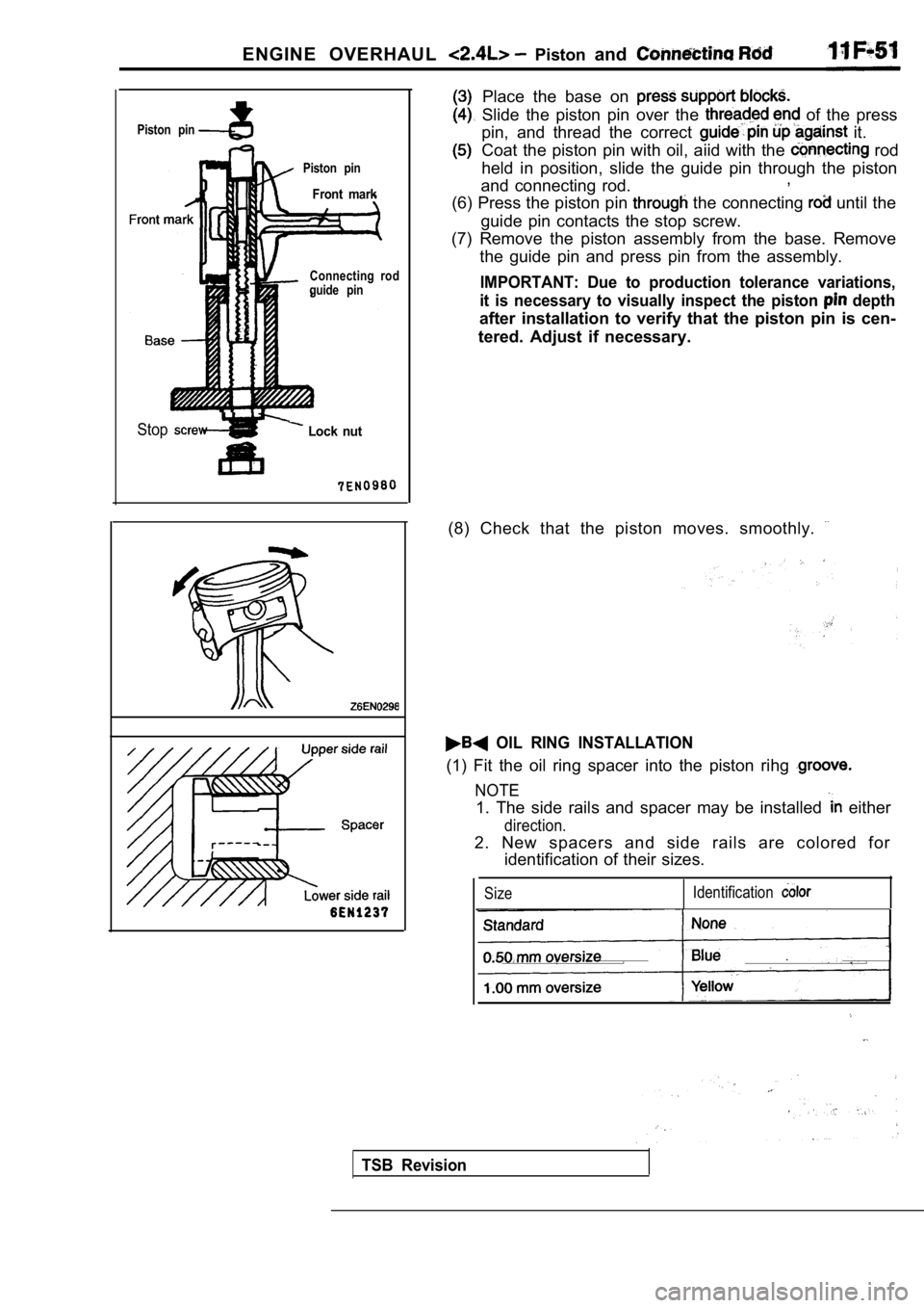
Place the base on
Slide the piston pin over the of the press
pin, and thread the correct
it.
Coat the piston pin with oil, aiid with the
rod
held in position, slide the guide pin through the p iston
and connecting rod. ,
(6) Press the piston pin
the connecting until the
guide pin contacts the stop screw.
(7) Remove the piston assembly from the base. Remov e
the guide pin and press pin from the assembly.
IMPORTANT: Due to production tolerance variations,
it is necessary to visually inspect the piston
depth
after installation to verify that the piston pin is cen-
tered. Adjust if necessary.
(8) Check that the piston moves. smoothly.
OIL RING INSTALLATION
(1) Fit the oil ring spacer into the piston rihg
NOTE
1. The side rails and spacer may be installed either
direction.
2. New spacers and side rails are colored for identification of their sizes.
Size Identification
TSB Revision
Page 365 of 2103
ENGINE OVERHAUL Piston and Rod
INSPECTION
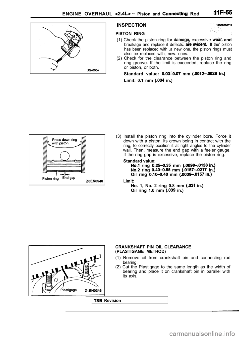
PISTON RING (1) Check the piston ring for
excessive and
breakage and replace if defects. If the’ piston
has been replaced with ,a new one, the piston rings must
also be replaced with, new. ones.
(2) Check for the clearance between the piston ring and
ring groove. If the limit is exceeded, replace the ring
or piston, or both.
Standard value:
mm
Limit: 0.1 mm in.)
(3) Install the piston ring into the cylinder bore. Force it
down with a piston, its crown being in contact with the
ring, to correctly position it at right angles to the cylinder
wall. Then, measure the end gap with a feeler gauge .
If the ring gap is excessive, replace the piston ri ng.
Standard value:
ring mm
ring mm in.)
Oil ring
mm
Limit:
No. 1, No. 2 ring 0.8 mm in.)
Oil ring 1.0 mm
in.)
Revision
CRANKSHAFT PIN OIL CLEARANCE
(PLASTIGAGE METHOD)
(1) Remove oil from crankshaft pin and connecting r od
bearing.
(2) Cut the Plastigage to the same length as the width of
bearing and place it on crankshaft pin in parallel with
its axis.
Page 368 of 2103
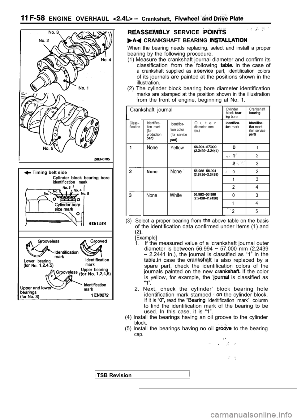
ENGINE OVERHAUL Crankshaft,
Timing belt side
Cylinder block bearing boreidentification mark
Lower bearing No.
Identification
mark
Upper bearing (for No.
Identification
mark
1
SERVICE
CRANKSHAFT BEARING
When the bearing needs replacing, select and instal l a proper
bearing by the following procedure.
(1) Measure the crankshaft journal diameter and con firm its
classification from the following
In the case of
a crankshaft supplied as part, identification colors
of its journals are painted at the positions shown in the
illustration.
(2) The cylinder block bearing bore diameter identi fication
marks are stamped at the position shown in the illustration
from the front of engine, beginning at No. 1.
Crankshaft journal
Classi-
fication Identifica-
tion mark
(for
production
None
NoneNone
Identifica-
tion color
(for service
Yellow
WhiteNone
1
2
3
02
13
2
4
03
14
25
(3)Select a proper bearing from above table on the basis
of the identification data confirmed under Items (1 ) and
[Example]
1.If the measured value of a ‘crankshaft journal oute r
diameter is between 56.994
57.000 mm (2.2439
2.2441 in.), the journal is classified as “1” in t he
case the is also replaced by a
spare part, check the identification colors of the
journals painted on the new
If the color
is yellow, for example, the
is classified as
.
2. Next, check the cylinder’ block bearing hole identification mark stamped
the cylinder block.
If it is read the ideritification mark” column
to find the identification mark of the bearing to b e
used. In this case, it is “1”.
(4) Install the bearings having an oil groove to th e cylinder
block.
(5) Install the bearings having no oil to the bearing
cap.
.
O u t e rdiameter mm
(in.)
Cylinder
block
bore
mark
Crankshaft
mark(for service
TSB Revision
Page 369 of 2103
E N G I N E O V E R H A U L Flywheel
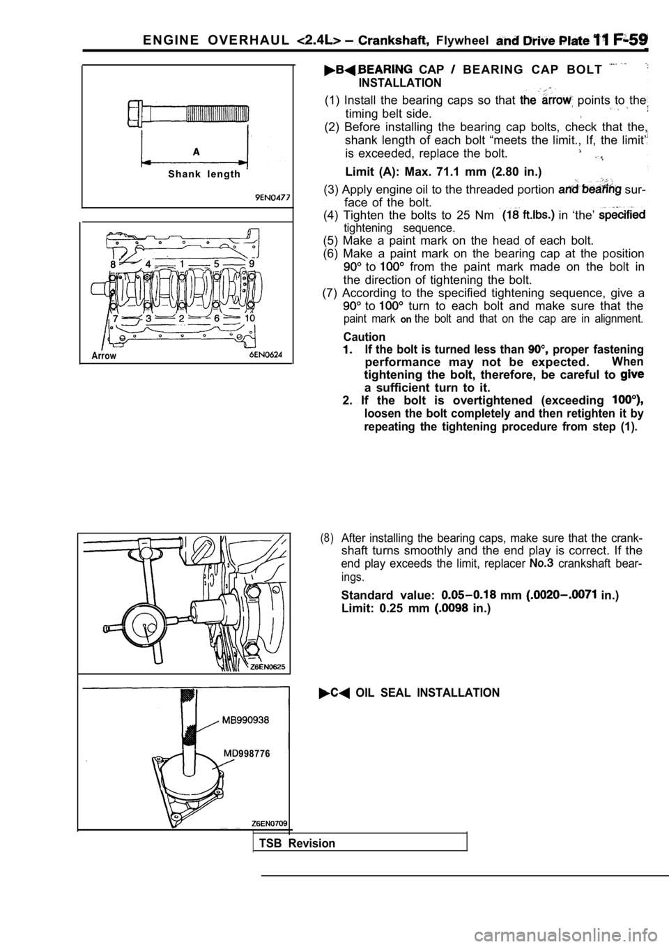
S h a n k l e n g t h
Arrow
CAP B E A R I N G C A P B O L T
INSTALLATION
(1) Install the bearing caps so that points to the
timing belt side.
(2) Before installing the bearing cap bolts, check that the,
shank length of each bolt “meets the limit., If, th e limit’
is exceeded, replace the bolt.
Limit (A): Max. 71.1 mm (2.80 in.)
(3) Apply engine oil to the threaded portion
sur-
face of the bolt.
(4) Tighten the bolts to 25 Nm
in ‘the’
tightening sequence.
(5) Make a paint mark on the head of each bolt.
(6) Make a paint mark on the bearing cap at the pos ition
to from the paint mark made on the bolt in
the direction of tightening the bolt.
(7) According to the specified tightening sequence, give a
to turn to each bolt and make sure that the
paint mark onthe bolt and that on the cap are in alignment.
Caution
If the bolt is turned less than proper fastening
performance may not be expected.When
tightening the bolt, therefore, be careful to
a sufficient turn to it.
2. If the bolt is overtightened (exceeding
loosen the bolt completely and then retighten it by
repeating the tightening procedure from step (1).
(8)After installing the bearing caps, make sure that t he crank-
shaft turns smoothly and the end play is correct. I f the
end play exceeds the limit, replacer crankshaft bear-
ings.
Standard value: mm in.)
Limit: 0.25 mm
in.)
OIL SEAL INSTALLATION
998776
TSB Revision
Page 371 of 2103
ENGINE OVERHAUL Crankshaft, Flywheel and, . .
INSPECTION11300880103
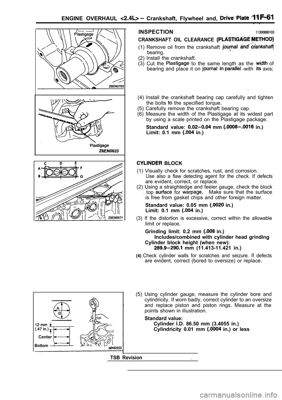
CRANKSHAFT OIL CLEARANCE
(1) Remove oil from the crankshaft
bearing.
(2) Install the crankshaft.
(3) Cut the
to the same length as the of
bearing and place it on
-with axis;
(4) Install the crankshaft bearing cap carefully an d tighten
the bolts
the specified torque.
(5) Carefully remove the crankshaft bearing cap.
(6) Measure the width of the Plastigage at its wide st part
by using a scale printed on the Plastigage package.
Standard value:
mm in.)
Limit: 0.1 mm
in.)
BLOCK
(1) Visually check for scratches, rust, and corrosi on.
Use also a flaw detecting agent for the check. If d efects
are evident, correct, or replace.
(2) Using a straightedge and feeler gauge, check th e block
top for Make sure that the surface
is free from gasket chips and other foreign matter.
Standard value: 0.05 mm
in.)
Limit: 0.1 mm
in.)
(3) If the distortion is excessive, correct within the allowable
limit or replace.
Grinding limit: 0.2 mm
in.)
Includes/combined with cylinder head grinding
Cylinder block height (when new):
mm (11.413-11.421 in.)
(4)Check cylinder walls for scratches and seizure. If defects
are evident, correct (bored to oversize) or replace.
Center
Bottom
TSB Revision
(5) Using cylinder gauge, measure the cylinder bore and
cylindricity. If worn badly, correct cylinder to an oversize
and replace piston and piston rings. Measure at the
points shown in illustration.
Standard value: Cylinder I.D. 86.50 mm (3.4055 in.)
Cylindricity 0.01 mm
in.) or less
Page 375 of 2103
ENGINE LUBRICATION Service
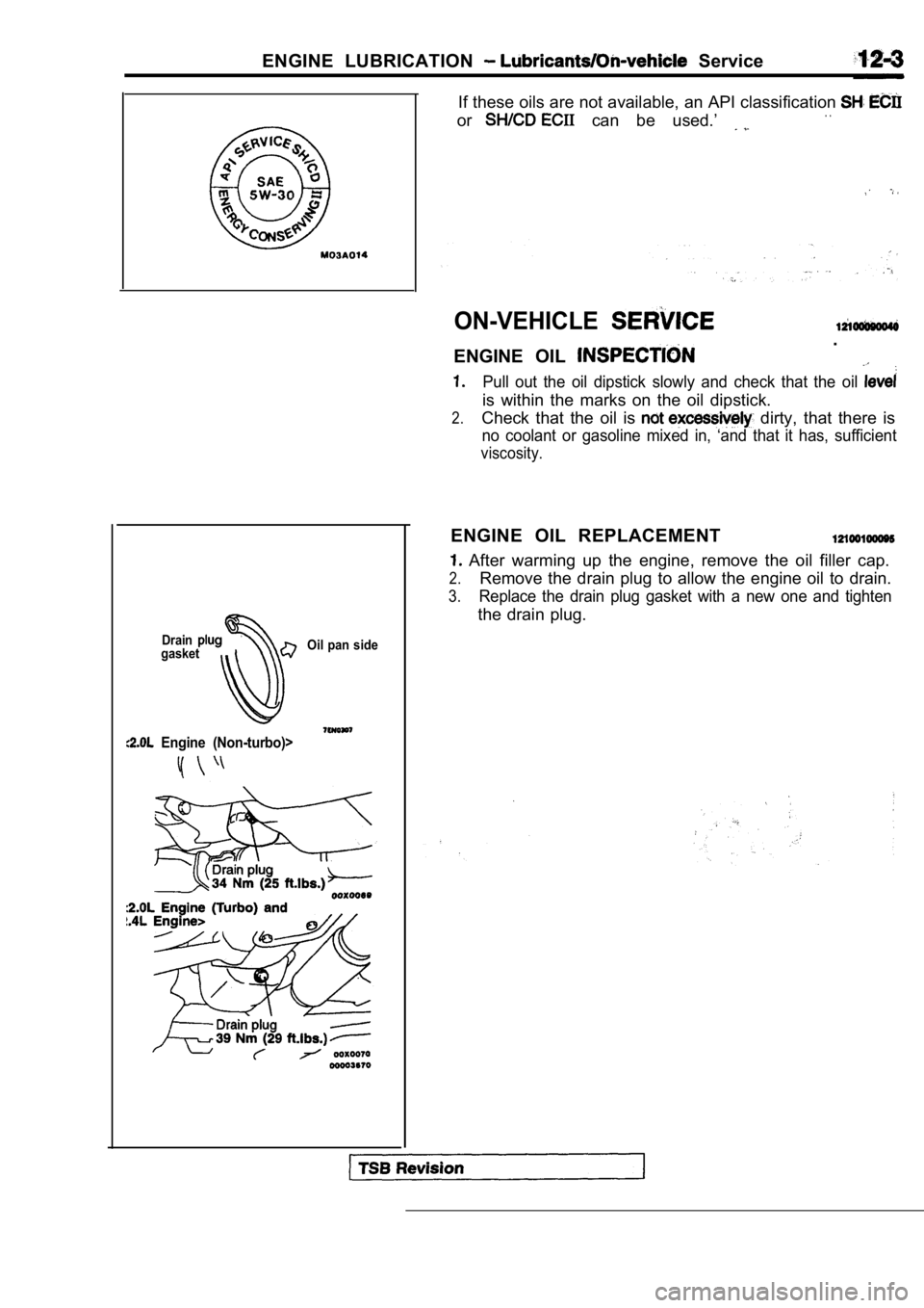
DraingasketOil pan side
Engine (Non-turbo)>
If these oils are not available, an API classificat
ion
or can be used.’ . .
ON-VEHICLE
ENGINE OIL
.
Pull out the oil dipstick slowly and check that the oil
is within the marks on the oil dipstick.
2.Check that the oil is dirty, that there is
no coolant or gasoline mixed in, ‘and that it has, sufficient
viscosity.
ENGINE OIL REPLACEMENT
After warming up the engine, remove the oil filler cap.
2.Remove the drain plug to allow the engine oil to drain.
3.Replace the drain plug gasket with a new one and ti ghten
the drain plug.
Page 376 of 2103
![MITSUBISHI SPYDER 1990 Service Manual PDF 12-4 L U B R I C A T I O N
EngineI
Turbo
4. Supply new engine oil through the oil filler.Engine oil total quantity:[including oil filter and oil cooler]
Engine (Non-turbo) arid](/img/19/57345/w960_57345-375.png "MITSUBISHI SPYDER 1990 Service Manual PDF 12-4 L U B R I C A T I O N
EngineI
Turbo
4. Supply new engine oil through the oil filler.Engine oil total quantity:[including oil filter and oil cooler]
Engine (Non-turbo) arid")
12-4 L U B R I C A T I O N
EngineI
Turbo
4. Supply new engine oil through the oil filler.Engine oil total quantity:[including oil filter and oil cooler]
Engine (Non-turbo) arid
4 . 3 (4 q t s . )
Engine (Turbo)>
4.4
(4.6 qts.)
5. Start and run the engine a
minutes.
6.Stop the engine and check the engine oil level is w ithin
the level range indicated on the oil dipstick.
.
NOTE
may be used for operation in very cold weather
areas where the lowest ambient temperature is below
OIL REPLACEMENT
1. Remove the engine oil filler cap.
2.Remove the engine oil drain plug, and drain out the engine
o i l .
3.Remove the engine oil filter by using the oil filter wrench.
4.Clean the oil filter mounting, surface of the oil f ilter bracket.
5. Coat engine oil to the O-ring of’new filter: .
6.Screw on the oil filter by hand until it touchesthe surface
of the flange and then tighten it with. the filter wrench:
etc.
Engine (Turbo) Engine>
lFor One full turn or 14 Nm
lFor or 17 Nm (12
E n g i n e ( N o n - t u r b o ) >
lFor 090: turn or 21 Nm (15
7. Add new engine oil through the oil filter.
8. Start and run engine and check for engine oil le aks.
9. After stopping engine, check oil level and reple nish as
necessary.
TSB Revision
Page 377 of 2103
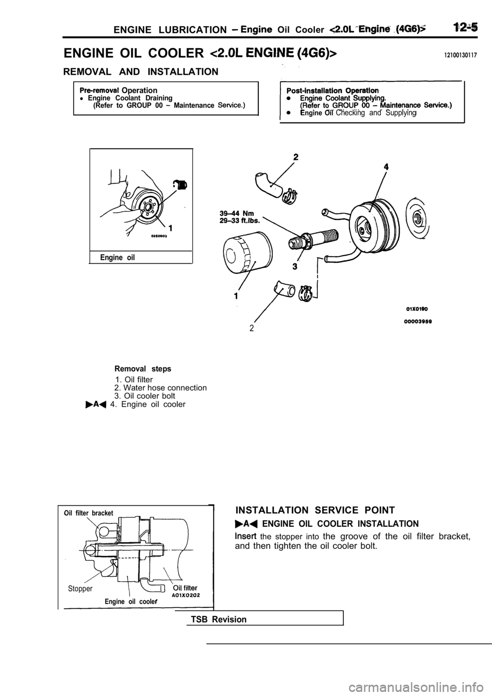
ENGINE LUBRICATION Oil Cooler
ENGINE OIL COOLER 12100130117
REMOVAL AND INSTALLATION
Operationl Engine Coolant Draining(Refer to GROUP 00 Maintenance
Engine oil
Engine Oil Checking and Supplying
2
Removal steps
1. Oil filter
2. Water hose connection
3. Oil cooler bolt
4. Engine oil cooler
Oil filter bracket
Stopper
Engine oil cooler
INSTALLATION SERVICE POINT
ENGINE OIL COOLER INSTALLATION
the stopper into the groove of the oil filter bracket,
and then tighten the oil cooler bolt.
TSB Revision