check oil MITSUBISHI SPYDER 1990 Service Owner's Manual
[x] Cancel search | Manufacturer: MITSUBISHI, Model Year: 1990, Model line: SPYDER, Model: MITSUBISHI SPYDER 1990Pages: 2103, PDF Size: 68.98 MB
Page 125 of 2103
![MITSUBISHI SPYDER 1990 Service Owners Manual ENGINE OVERHAUL Belt
Phillips screwdriver
TSBRevision
(4) a Phillips screwdriver [shank diameter 8 mm
in.)] through the hole.
If it can be inserted as deep as 60 mm (2.4 or](/img/19/57345/w960_57345-124.png "MITSUBISHI SPYDER 1990 Service Owners Manual ENGINE OVERHAUL Belt
Phillips screwdriver
TSBRevision
(4) a Phillips screwdriver [shank diameter 8 mm
in.)] through the hole.
If it can be inserted as deep as 60 mm (2.4 or")
ENGINE OVERHAUL Belt
Phillips screwdriver
TSBRevision
(4) a Phillips screwdriver [shank diameter 8 mm
in.)] through the hole.
If it can be inserted as deep as 60 mm (2.4 or more;
the timing ‘marks are correctly aligned. If the inserted
depth is only
mm in.), turn the oil’ pump
sprocket one turn and
marks. Then check
to ensure that the screwdriver can be inserted 60 m m
(2.4 in.) or more. Keep the screwdriver inserted the
installation of the timing belt is finished.
NOTE
Step (4) is performed to ensure that the oil pump sprocket
is correctly positioned with reference to the counterbal-
ance shafts.
(5) Thread the timing belt over the intake side cam shaft
sprocket and fix it at indicated position by a bulldog clip.
(6) Thread the timing belt over the exhaust side sp rocket,
aligning the timing marks with the cylinder head top surface
using two wrenches.
(7) Fix the belt at indicated, position
a bulldog clip.
Page 136 of 2103
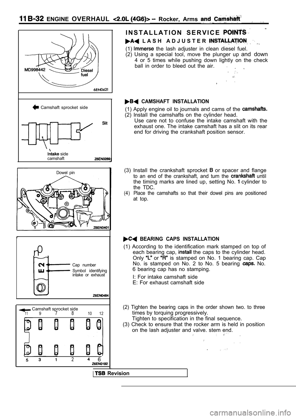
ENGINE OVERHAUL Rocker, Arms
Camshaft sprocket side
sidecamshaft
Dowel pin
n0
Cap number
Symbol identifying
intake or exhaust
0
Camshaft sprocket side1197 810 12
2 6
I N S T A L L A T I O N S E R V I C E
L A S H A D J U S T E R
(1) the lash adjuster in clean diesel fuel.
(2) Using a special tool, move the plunger up and down
4 or 5 times while pushing down lightly on the chec k
ball in order to bleed out the air.
,
CAMSHAFT INSTALLATION
(1) Apply engine oil to journals and cams of the
(2) Install the camshafts on the cylinder head. Use care not to confuse the intake camshaft with th e
exhaust one. The intake camshaft has a slit on its rear
end for driving the crankshaft position sensor.
(3) Install the crankshaft sprocket
or spacer and flange
to an end of the crankshaft, and turn the until
the timing marks are lined up, setting No. cylinder to
the TDC.
(4)Place the camshafts so that their dowel pins are po sitioned
at top.
BEARING CAPS INSTALLATION
(1) According to the identification mark stamped on top of
each bearing cap,
the caps to the cylinder head.
Only
or is stamped on No. 1 bearing cap. Cap
No. is stamped on No. 2 to No. 5 bearing
No.
6 bearing cap has no stamping.
I: For intake camshaft side
E: For exhaust camshaft side
(2) Tighten the bearing caps in the order shown two . to three
times by torquing progressively.
Tighten to specification in the final sequence.
(3) Check to ensure that the rocker arm is held in position
on the lash adjuster and valve. stem end.
.
Revision
Page 154 of 2103
Front Case, Counterbalance
ENGINE Shaft and
INSPECTION
FRONT CASE
(1) Check oil holes for clogging and if necessary.
(2)’ Check left counterbalance shaft front bearing
for
Wear, damage and seizure. If there is anything wron g’
with the section, replace the front
(3) Check the front case for cracks and other damag e.
place cracked or damaged front case.
OIL SEAL
(1) Check the oil seal lip for wear and damage. Rep lace
oil seal if necessary.
(2) Check the oil seal lip for deterioration. Repla ce oil seal
if necessary.
I
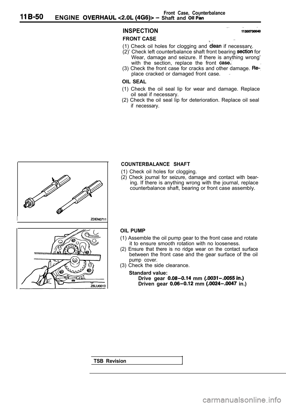
COUNTERBALANCE SHAFT
(1) Check oil holes for clogging.
(2) Check journal for seizure, damage and contact w ith bear-
ing. If there is anything wrong with the journal, replace
counterbalance shaft, bearing or front case assembl y.
OIL PUMP
(1) Assemble the oil pump gear to the front case an d rotate
it to ensure smooth rotation with no looseness.
(2) Ensure that there is no ridge wear on the conta ct surface
between the front case and the gear surface of the oil
pump cover.
(3) Check the side clearance.
Standard value: Drive gear
mm
Driven gear mm in.)
TSB Revision
Page 157 of 2103
ENGINE OVERHAUL Piston and Connecting Rod
Piston pin
Base
Front
Base
Connecting rod
guide pin
StopLock nut
1
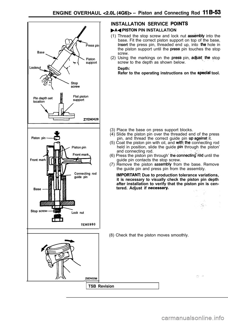
INSTALLATION SERVICE
PIN INSTALLATION
(1) Thread the stop screw and lock nut
into the
base. Fit the correct piston support on top of the base,
the press pin, threaded end up, into hole in
the piston support until the
pin touches the stop
screw.
(2) Using the markings on the pin, stop
screw to the depth as shown below.
Depth: Refer to the operating instructions on the
tool.
(3) Place the base on press support blocks.
(4) Slide the piston pin over the threaded end of t he press
pin, and thread the correct guide pin
it.
(5) Coat the piston pin with oil, and
connecting rod
held in position, slide the guide
through the piston’
and connecting rod.
(6) Press the piston pin through’ until the
guide pin contacts the stop screw.
(7) Remove the piston
from the base. Remove
the guide pin and press pin from the assembly.
Due to production tolerance variations,
it is necessary to visually check the piston pin de pth
after installation to verify that the piston pin is cen-
tered. Adjust if
(8) Check that the piston moves smoothly.
TSB Revision
Page 159 of 2103
ENGINE OVERHAUL and
CrankshaftUpper side
side
ring gap and spacer gaprail
Timing belt side
Front mark
Identification mark
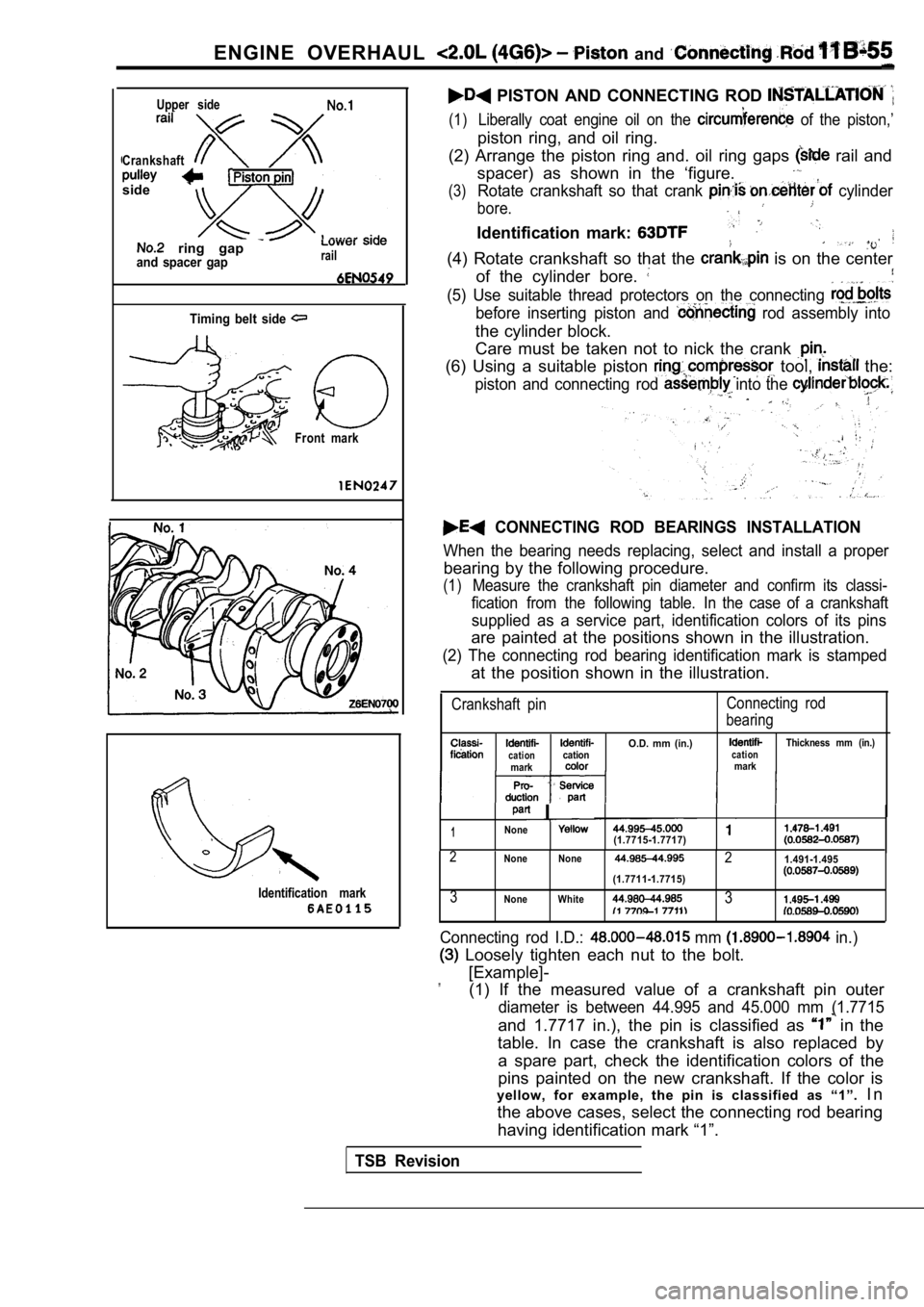
PISTON AND CONNECTING ROD
(1)Liberally coat engine oil on the of the piston,’
piston ring, and oil ring.
(2) Arrange the piston ring and. oil ring gaps
rail and
spacer) as shown in the ‘figure.
(3)Rotate crankshaft so that crank cylinder
bore.
Identification mark:
(4) Rotate crankshaft so that the is on the center
of the cylinder bore.
(5) Use suitable thread protectors on the connectin g
before inserting piston and rod assembly into
the cylinder block.
Care must be taken not to nick the crank
(6) Using a suitable piston tool, the:
piston and connecting rod into the ,
CONNECTING ROD BEARINGS INSTALLATION
When the bearing needs replacing, select and instal l a proper
bearing by the following procedure.
(1)Measure the crankshaft pin diameter and confirm its classi-
fication from the following table. In the case of a crankshaft
supplied as a service part, identification colors of its pins
are painted at the positions shown in the illustrat ion.
(2) The connecting rod bearing identification mark is stamped
at the position shown in the illustration.
Crankshaft pinConnecting rod
bearing
O.D. mm (in.)Thickness mm (in.)cationcationcationmarkmark
I
1None(1.7715-1.7717)
2None None21.491-1.495
(1.7711-1.7715)
3None White3
Connecting rod I.D.: mm in.)
Loosely tighten each nut to the bolt.
[Example]-
”(1) If the measured value of a crankshaft pin outer
diameter is between 44.995 and 45.000 mm (1.7715
and 1.7717 in.), the pin is classified as in the
table. In case the crankshaft is also replaced by
a spare part, check the identification colors of th e
pins painted on the new crankshaft. If the color is
yellow, for example, the pin is classified as “1”. I n
the above cases, select the connecting rod bearing having identification mark “1”.
TSB Revision
Page 161 of 2103
ENGINE OVERHAUL
11300850104
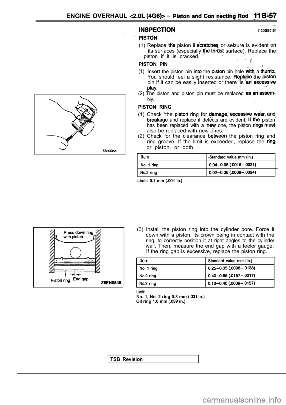
(1) Replace piston ii or seizure is evident
its surfaces (especially surface). Replace the
piston if it is cracked.
PISTON PIN
(1) the piston pin the pin hole a
You should feel a slight resistance. the
pin if it can be easily inserted or there ‘is .
(2) The piston and piston pin must be replaced
bly.
PISTON RING
(1) Check ‘the ring for
and replace if defects are evident: piston
has been replaced with a
one, the piston
also be replaced with new ones.
(2) Check for the clearance
the piston ring and
ring groove. If the limit is exceeded, replace the
or piston, or both.
Item
No. 1 ring
ring
Limit: 0.1 mm
in.)
-Standard value mm (in.)
(3) Install the piston ring into the cylinder bore. Force it
down with a piston, its crown being in contact with the
ring, to correctly position it at right angles to the cylinder
wall. Then, measure the end gap with a feeler gauge .
If the ring gap is excessive, replace the piston ri ng.
Standard value mm (in.)
No. 1 ring
ring
ring
Limit:No. 1, No. 2 ring 0.8 mm in.)
Oil ring 1.0 mm in.)
TSB Revision
Page 165 of 2103
![MITSUBISHI SPYDER 1990 Service Owners Manual E N G I N E O V E R H A U L
ed
(for No. tion mark
Upper and lower (for No.3)
Identification
mark
1
Shank length
[Example]
(1) If the measured value of a crankshaft
diameter is b](/img/19/57345/w960_57345-164.png "MITSUBISHI SPYDER 1990 Service Owners Manual E N G I N E O V E R H A U L
ed
(for No. tion mark
Upper and lower (for No.3)
Identification
mark
1
Shank length
[Example]
(1) If the measured value of a crankshaft
diameter is b")
E N G I N E O V E R H A U L
ed
(for No. tion mark
Upper and lower (for No.3)
Identification
mark
1
Shank length
[Example]
(1) If the measured value of a crankshaft
diameter is between 56.994 mm (2.2439
2.2441 in.), the journal is in the’
case the is also replaced by a
spare part, check the identification colors of the
journals painted on the
crankshaft. If the color’
is yellow, for example,.
journal is classified as
(2)
check the cylinder block bearing hole
mark stamped on the cylinder block.
If it is “O”, read the “Bearing identification column
to find the identification mark of the bearing to b e
used. In this case, it is “1”.
(4)
the bearings oil groove to the cylinder
block.
(5) Install the bearings having no oil to the bearing
caps.
CAP B E A R I N G C A P B O L T
INSTALLATION
(1) Install the bearing caps so that their arrows directed
to the timing belt side.
(2) Before installing the bearing cap bolts, check that the
shank length of each bolt meets the limit.
limit
is exceeded, replace the bolt.
(A): Max. 71.1 mm (2.79 in.)
(3) Apply engine oil to the threaded portion and be aring sur-
face of the bolt.
(4) Tighten the bolts to 25 Nm (16
in the specified
tightening sequence.
(5) Make a paint mark on the head of each bolt.
(6) Make a paint mark on the bearing cap at the pos ition
to from the paint mark made on the bolt in
the direction of tightening the bolt.
(7) According to the specified tightening sequence, give a
to turn to each bolt and make sure that the
paint mark on the bolt and that on the cap are in a lignment.
Caution
(1) If
thebolt is turned less than proper
performance may not be expected.
tightening the bolt, therefore, be careful to
a sufficient turn to it.
( 2 ) I f t h e b o l t i s
loosen the bolt completely and then retlghten
by repeating the tightening procedure from step
TSB Revision
Page 167 of 2103
ENGINE OVERHAUL and
A
INSPECTION
O I L C L E A R A N C E
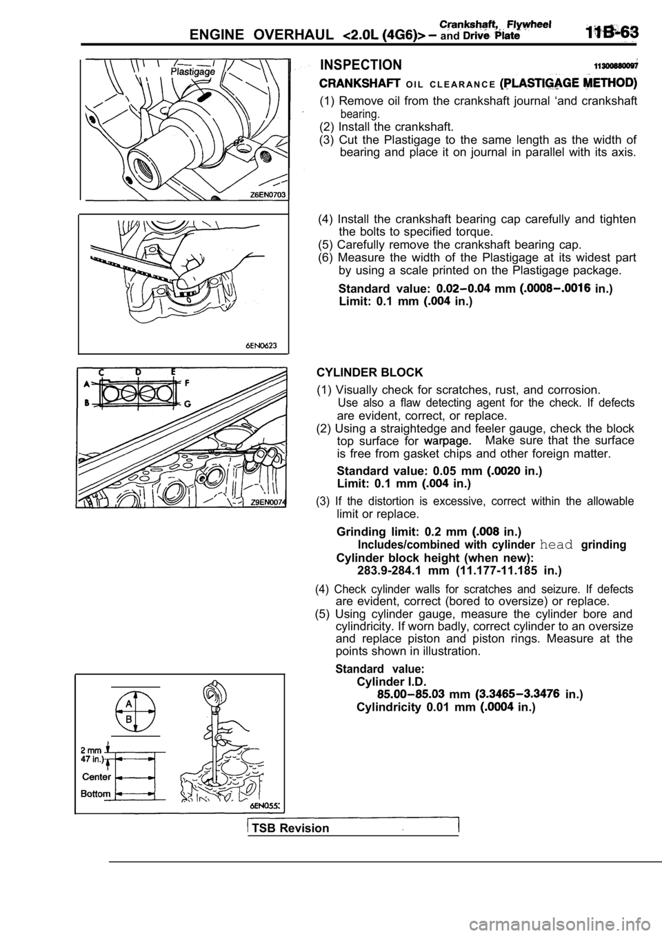
(1) Remove oil from the crankshaft journal ‘and crankshaft
bearing.
(2) Install the crankshaft.
(3) Cut the Plastigage to the same length as the wi dth of
bearing and place it on journal in parallel with it s axis.
(4) Install the crankshaft bearing cap carefully an d tighten
the bolts to specified torque.
(5) Carefully remove the crankshaft bearing cap.
(6) Measure the width of the Plastigage at its wide st part
by using a scale printed on the Plastigage package.
Standard value:
mm in.)
Limit: 0.1 mm
in.)
CYLINDER BLOCK (1) Visually check for scratches, rust, and corrosi on.
Use also a flaw detecting agent for the check. If d efects
are evident, correct, or replace.
(2) Using a straightedge and feeler gauge, check th e block
top surface for
Make sure that the surface
is free from gasket chips and other foreign matter.
Standard value: 0.05 mm
in.)
Limit: 0.1 mm
in.)
(3) If the distortion is excessive, correct within the allowable
limit or replace.
Grinding limit: 0.2 mm
in.)
Includes/combined with cylinder headgrinding
Cylinder block height (when new): 283.9-284.1 mm (11.177-11.185 in.)
(4) Check cylinder walls for scratches and seizure. If defects
are evident, correct (bored to oversize) or replace.
(5) Using cylinder gauge, measure the cylinder bore and
cylindricity. If worn badly, correct cylinder to an oversize
and replace piston and piston rings. Measure at the
points shown in illustration.
Standard value:
Cylinder I.D.
mm in.)
Cylindricity 0.01 mm
in.)
TSB Revision
Page 171 of 2103
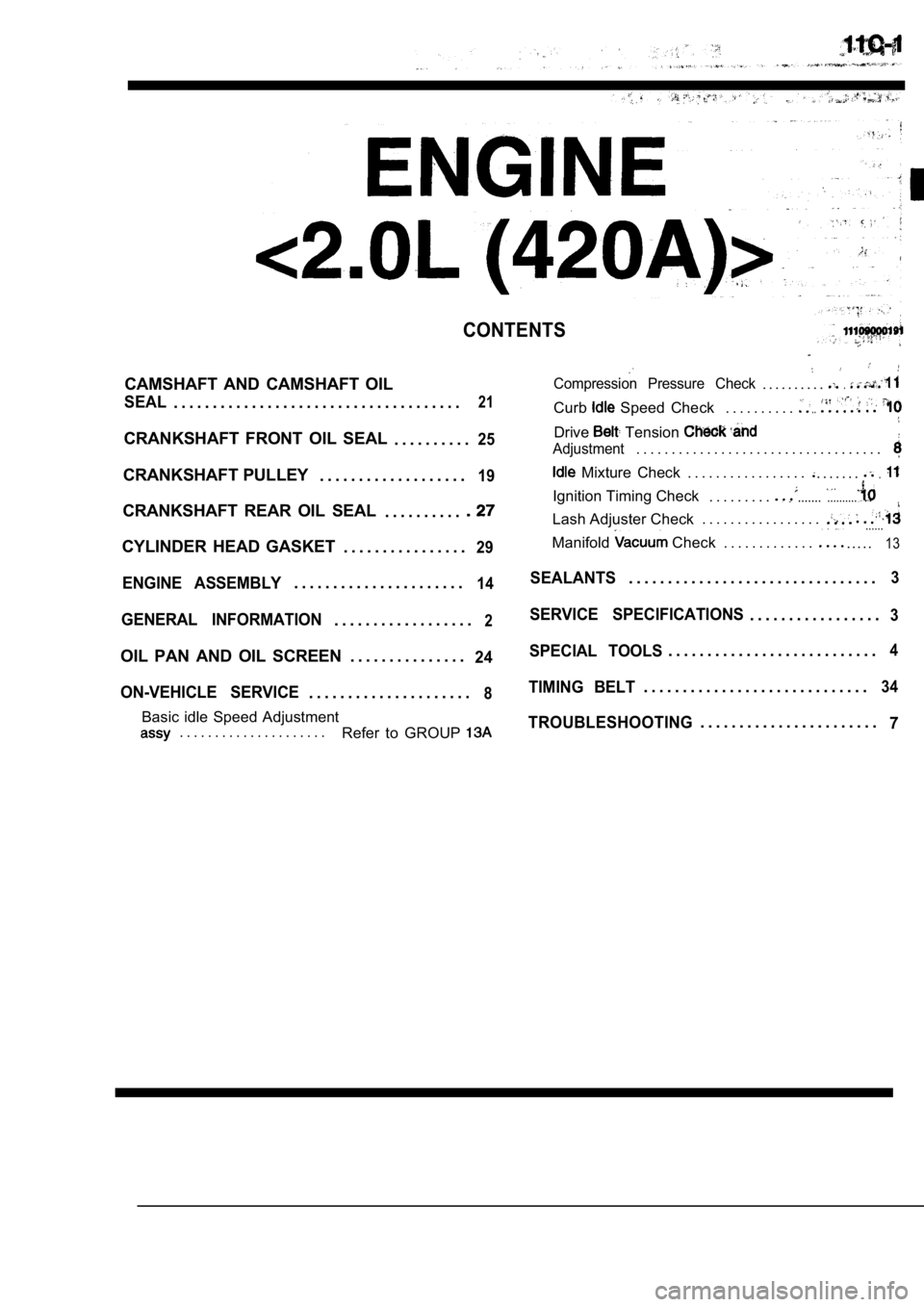
CONTENTS
CAMSHAFT AND CAMSHAFT OIL
SEAL. . . . . . . . . . . . . . . . . . . . . . . . . . . . . . . . . . . . .21
CRANKSHAFT FRONT OIL SEAL. . . . . . . . . .25
CRANKSHAFT PULLEY. . . . . . . . . . . . . . . . . . .19
CRANKSHAFT REAR OIL SEAL
. . . . . . . . . .
CYLINDER HEAD GASKET. . . . . . . . . . . . . . . .29
ENGINE ASSEMBLY. . . . . . . . . . . . . . . . . . . . . .14
GENERAL INFORMATION. . . . . . . . . . . . . . . . . .2
OIL PAN AND OIL SCREEN . . . . . . . . . . . . . . .24
ON-VEHICLE SERVICE
. . . . . . . . . . . . . . . . . . . . .8
Basic idle Speed Adjustment. . . . . . . . . . . . . . . . . . . . . Refer to GROUP
Compression Pressure Check. . . . . . . . . ..
Curb Speed Check . . . . . . . . . ...
Drive Tension
Adjustment. . . . . . . . . . . . . . . . . . . . . . . . . . . . . . . . . . .
Mixture Check . . . . . . . . . . . . . . . . .. . . . . . ..
Ignition Timing Check. . . . . . . . .....................
Lash Adjuster Check . . . . . . . . . . . . . . . . .
......
. . . . .
Manifold Check . . . . . . . . . . . . .13
SEALANTS. . . . . . . . . . . . . . . . . . . . . . . . . . . . . . . .3
SERVICE SPECIFICATIONS. . . . . . . . . . . . . . . . .3
SPECIAL TOOLS. . . . . . . . . . . . . . . . . . . . . . . . . . .4
TIMING BELT. . . . . . . . . . . . . . . . . . . . . . . . . . . . .34
TROUBLESHOOTING. . . . . . . . . . . . . . . . . . . . . . .
7
Page 173 of 2103
ENGINE ‘Service
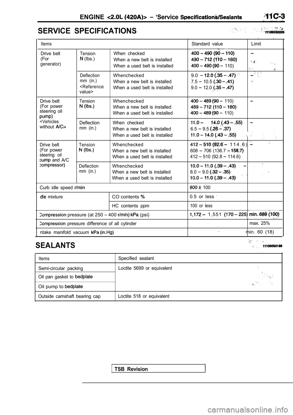
SERVICE SPECIFICATIONS
Items
Drive belt
(For
generator)
Standard value Limit
TensionWhen checked
(Ibs.) When a new belt is installed
When a used belt is installed
110)
DeflectionWhenchecked9.0
mm (in.)When a new belt is installed 7.5 10.5
Drive beltTensionWhenchecked
(For power
When a new belt is installed
steering oil
When a used belt is installed
mm (in.)When a new belt is installed
When a used belt is installed
Drive belt
TensionWhenchecked
(For power
When a new belt is installedsteering oil
and A/C When a used belt is installed
DeflectionWhenchecked
mm (in.)When a new belt is installed
When a used belt is installed
Curb idle speed
mixtureCO contents
HC contents ppm
pressure (at 250 400 (psi)
pressure difference of all cylinder
ntake manifold vacuum
110)
110)
6.5 9.5
1 1 4 . 6 )
608 706 (136.7
412 510 (92.8 114.6)
8.0 9.0
100
0.5 or less
100 or less
1 , 5 5 1
max. 25%
min. 60 (18)
SEALANTS
Items
Semi-circular packing
Oil pan gasket to
Oil pump to
Outside camshaft bearing cap Specified sealant
Loctite 5699 or equivalent
Loctite 518 or equivalent
TSB Revision