timing belt MITSUBISHI SPYDER 1990 Service Service Manual
[x] Cancel search | Manufacturer: MITSUBISHI, Model Year: 1990, Model line: SPYDER, Model: MITSUBISHI SPYDER 1990Pages: 2103, PDF Size: 68.98 MB
Page 206 of 2103
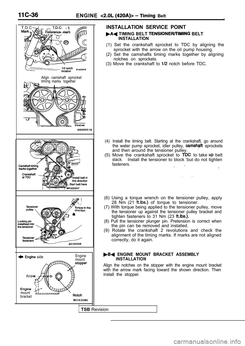
ENGINE Belt
Reference mark
T.D.C.
Align camshaft sprockettimingmarks together
side
Arra
mount
bracket Engine
mount
INSTALLATION SERVICE POINT
TIMING BELT BELT
INSTALLATION
(1) Set the crankshaft sprocket to TDC by aligning the
sprocket with the arrow on the oil pump housing.
(2) Set the camshafts timing marks together by alig ning
notches on sprockets.
(3) Move the crankshaft to notch before TDC.
(4) Install the timing belt. Starting at the crankshaft, go around
the water pump sprocket, idler pulley, sprockets
and then around the tensioner pulley.
(5) Move the crankshaft sprocket to to take belt
slack.Install the tensioner to block ‘but do not tighten
fasteners.
(6) Using a torque wrench on the tensioner pulley, apply
28 Nm (21
of torque to tensioner..
(7) With torque being applied to the tensioner pull ey, move
the tensioner up against the tensioner pulley brack et and
tighten fasteners to 31 Nm (23
(8) Pull the tensioner plunger pin. Pretension is correct when
the pin can be removed and installed.
(9) Rotate the crankshaft 2 revolutions and check t he
alignment of the timing marks. If marks are not ali gned
correctly, do it again.
ENGINE MOUNT BRACKET ASSEMBLY
INSTALLATION
Align the notches on the stopper with the engine mo unt bracket
with the arrow mark facing toward the shown direction. Then
install the stopper.
TSB Revision
Page 207 of 2103
CONTENTS
CAMSHAFT AND CAMFOLLOWER............28
COOLING SYSTEMCOMPONENTS.............21
CRANKSHAFT............................................55
CYLINDER HEADANDVALVE....................32
EXHAUST MANIFOLD.................................27
FUEL AND EMISSION CONTROL PARTS...
GENERAL INFORMATION.............................2
General Specifications
.................................2
GENERATOR..............................................11
IGNITION SYSTEM......................................12
INTAKE MANIFOLD
OIL PAN AND PUMP. . , . . . . . . . . . . . . . . . . . . . . . . . . .
OIL PUMP
P I S T O N , C O N N E C T I N G R O D A N D
CYLINDER BLOCK. . . . . . . . . . . . . . . . . . . . 45.
SPECIAL TOOLS. . . . . . . . . . . . . . . . . . . . . . . . . . . . . . . . . . . . . . . .9
SPECIFICATIONS3
Sealants . . . . . . . . . . . . . . . . . . . . .7
Specifications.. . . . . . . . . . . . . . .3
Torque Specifications. . . . . . . . . . . . . . . . . .6
TIMINGBELT.. . . . . . . . . . . . . . . . . . . . . . . . . . . . . . . . . . . . . . . 16
Page 212 of 2103
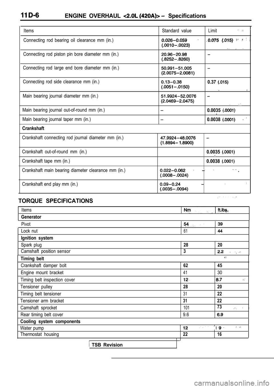
ENGINE OVERHAUL Specifications
Items
Connecting rod bearing oil clearance mm (in.)Standard value
Limit
Connecting rod piston pin bore diameter mm (in.)
Connecting rod large end bore diameter mm (in.)
Connecting rod side clearance mm (in.)
Main bearing journal diameter mm (in.)0.37
.
Main bearing journal out-of-round mm (in.)
Main bearing journal taper mm (in.)
Crankshaft
0.0035.
0.0038
Crankshaft connecting rod journal diameter mm (in.)
Crankshaft out-of-round mm (in.)
Crankshaft tape mm (in.)
Crankshaft main bearing diameter clearance mm (in.)0.0035
0.0038
.
Crankshaft end play mm (in.)
TORQUE SPECIFICATIONS
Items
Generator
Pivot
Lock nut61
Ignition system
Spark plug28 20
Camshaft position sensor3
Timing belt
Crankshaft damper bolt62 45
Engine mount bracket4130
Timing belt inspection cover
Tensioner pulley28 20
Timing belt tensioner3122
Tensioner arm bracket3122
Camshaft sprocket10173
Rear timing belt cover 9.6
Cooling system components
Water pump
Thermostat housing2216
TSB Revision
Page 222 of 2103
E N G I N E O V E R H A U L
TIMING BELT11301860021
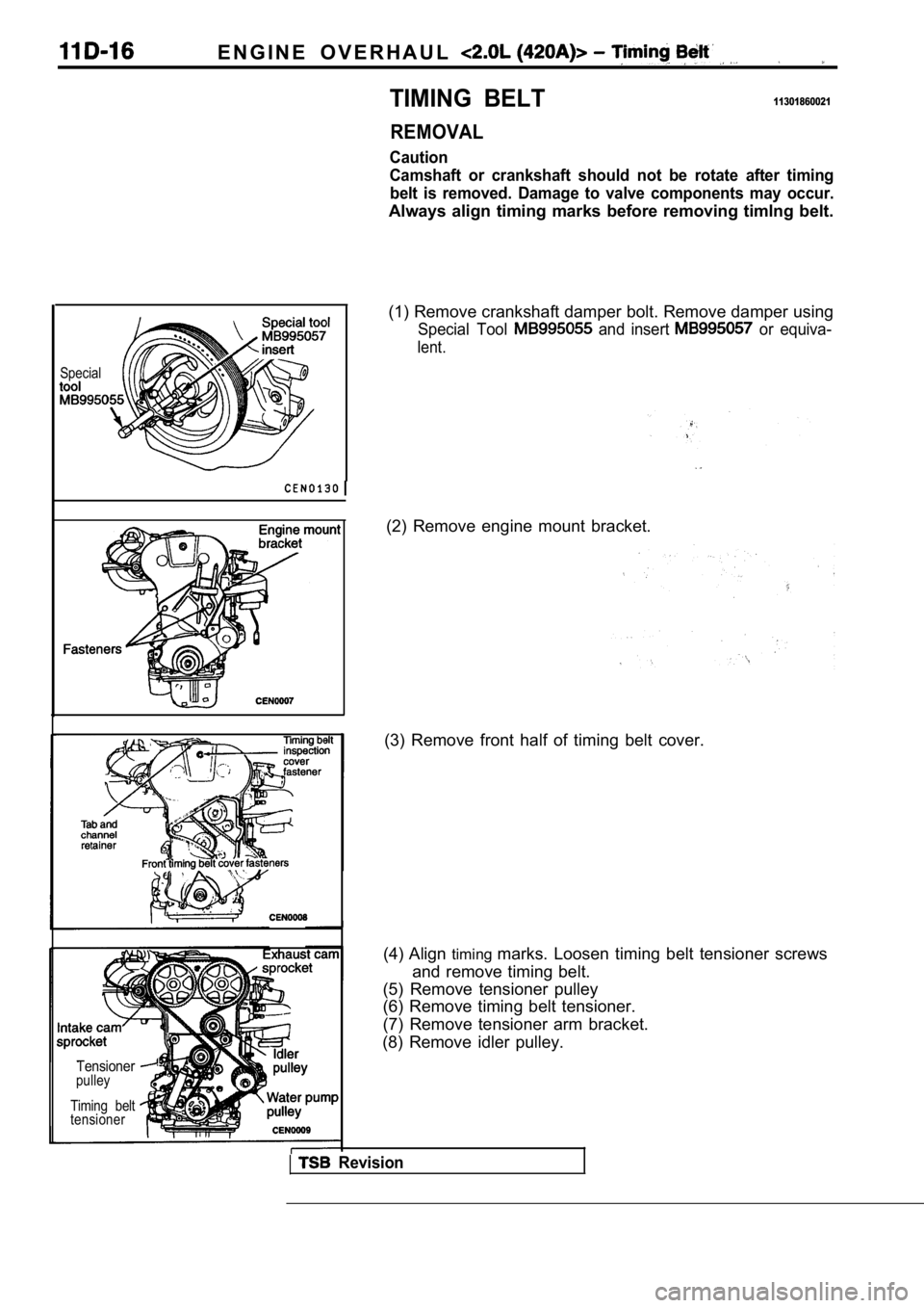
REMOVAL
Caution
Camshaft or crankshaft should not be rotate after timing
belt is removed. Damage to valve components may occ ur.
Always align timing marks before removing timlng belt.
Special
Tensionerpulley
Timing belt
tensioner
(1) Remove crankshaft damper bolt. Remove damper us ing
Special Tool and insert or equiva-
lent.
(2) Remove engine mount bracket.
(3) Remove front half of timing belt cover.
(4) Align timingmarks. Loosen timing belt tensioner screws
and remove timing belt.
(5) Remove tensioner pulley
(6) Remove timing belt tensioner.
(7) Remove tensioner arm bracket.
(8) Remove idler pulley.
Revision
Page 223 of 2103
ENGINE OVERHAUL Belt
Tensioner
pin
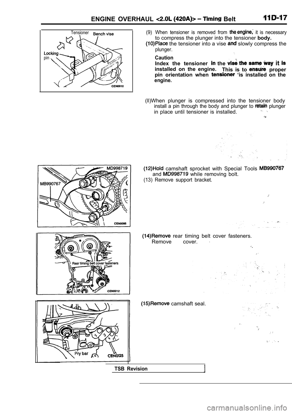
(9) When tensioner is removed from it is necessary
to compress the plunger into the tensioner body.
the tensioner into a vise slowly compress the
plunger.
Caution
Index the tensioner the it
installed on the engine.
This is to proper
pin orientation when
‘is installed on the
engine.
(ll)When plunger is compressed into the tensioner b ody
install a pin through the body and plunger to plunger
in place until tensioner is installed.
camshaft sprocket with Special Tools
and while removing bolt.
(13) Remove support bracket.
rear timing belt cover fasteners.
Remove cover.
camshaft seal.
.
TSB Revision
Page 224 of 2103
ENGINE OVERHAUL Timing
INSTALLATION11301870017
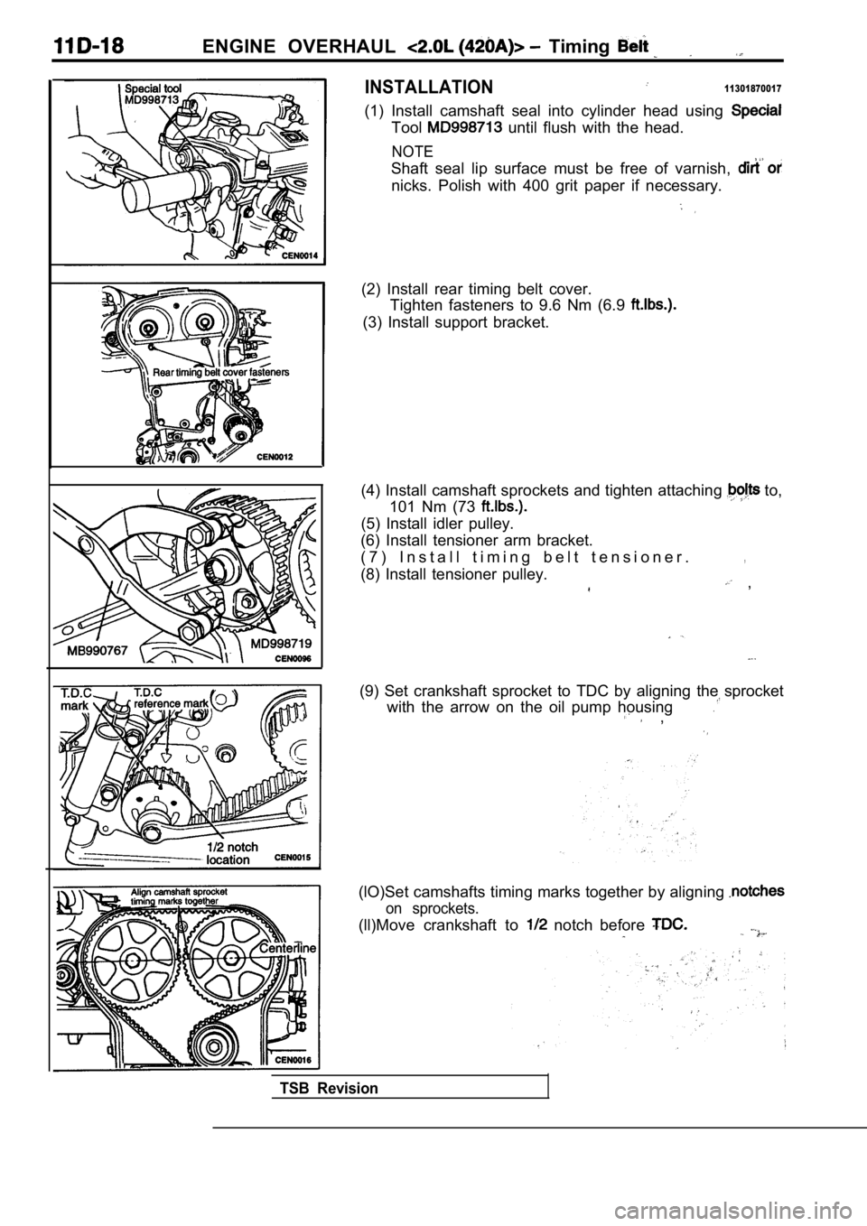
(1) Install camshaft seal into cylinder head using
Tool until flush with the head.
NOTE
Shaft seal lip surface must be free of varnish,
nicks. Polish with 400 grit paper if necessary.
(2) Install rear timing belt cover.Tighten fasteners to 9.6 Nm (6.9
(3) Install support bracket.
(4) Install camshaft sprockets and tighten attachin g
to,
101 Nm (73
(5) Install idler pulley.
(6) Install tensioner arm bracket.
( 7 ) I n s t a l l t i m i n g b e l t t e n s i o n e r .
(8) Install tensioner pulley.
,
,
(9) Set crankshaft sprocket to TDC by aligning the sprocket
with the arrow on the oil pump housing
,
(lO)Set camshafts timing marks together by aligning
on sprockets.
(ll)Move crankshaft to notch before
TSB Revision
Page 225 of 2103
ENGINE OVERHAUL Belt
TDCInstall belt in
‘this
here
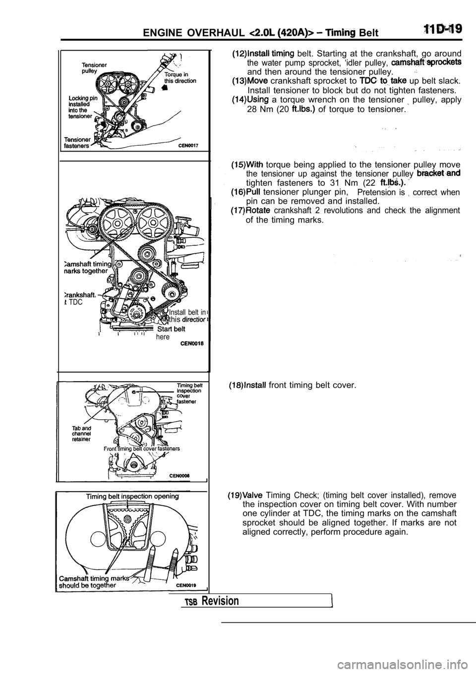
belt. Starting at the crankshaft, go around
the water pump sprocket, ‘idler pulley,
and then around the tensioner pulley.
crankshaft sprocket to up belt slack.
Install tensioner to block but do not tighten faste ners.
a torque wrench on the tensioner pulley, apply
28 Nm (20
of torque to tensioner.
torque being applied to the tensioner pulley move
the tensioner up against the tensioner pulley
tighten fasteners to 31 Nm (22
tensioner plunger pin,Pretension is correct when
pin can be removed and installed.
crankshaft 2 revolutions and check the alignment
of the timing marks.
front timing belt cover.
Timing Check; (timing belt cover installed), remov e
the inspection cover on timing belt cover. With num ber
one cylinder at TDC, the timing marks on the camsha ft
sprocket should be aligned together. If marks are n ot
aligned correctly, perform procedure again.
Revision
Page 235 of 2103
ENGINE OVERHAUL Camshaft Cam
INSTALLATION
I
Front bearing cap (No. cap)
diameter bead of Loctite 51817
Left rear bearing cap cap)
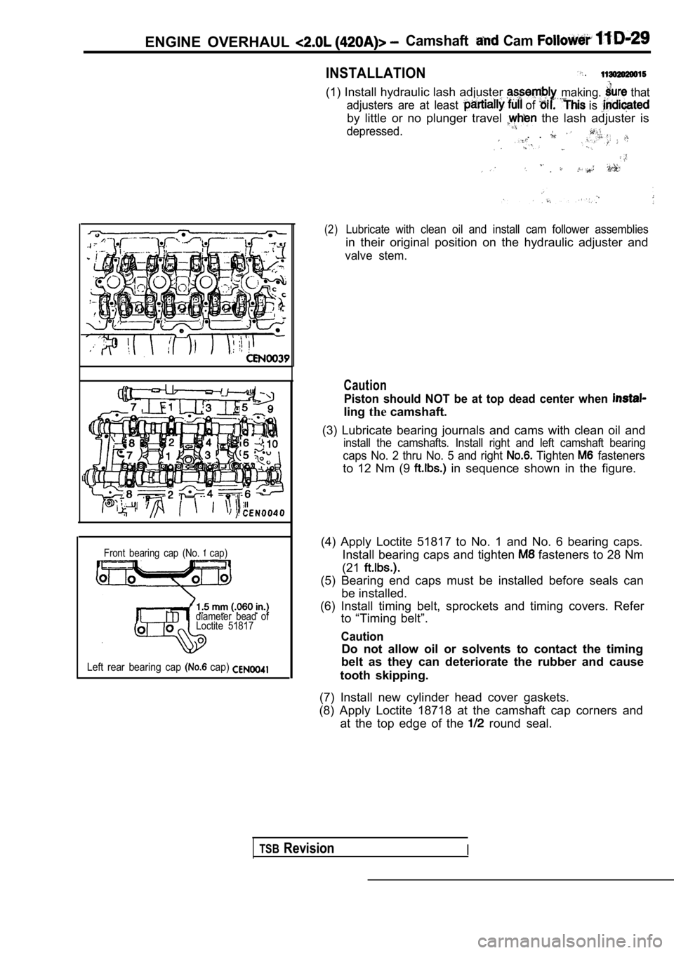
(1) Install hydraulic lash adjuster
adjusters are at least of
making. that
is
by little or no plunger travel the lash adjuster is
depressed.. .
(2)Lubricate with clean oil and install cam follower a ssemblies
in their original position on the hydraulic adjuster and
valve stem.
Caution
Piston should NOT be at top dead center when
lingthecamshaft.
(3) Lubricate bearing journals and cams with clean oil and
install the camshafts. Install right and left camshaft bearing
caps No. 2 thru No. 5 and right Tighten fasteners
to 12 Nm (9 in sequence shown in the figure.
(4) Apply Loctite 51817 to No. 1 and No. 6 bearing caps.
Install bearing caps and tighten
fasteners to 28 Nm
(21
(5) Bearing end caps must be installed before seals can
be installed.
(6) Install timing belt, sprockets and timing cover s. Refer
to “Timing belt”.
Caution
Do not allow oil or solvents to contact the timing
belt as they can deteriorate the rubber and cause
tooth skipping.
(7) Install new cylinder head cover gaskets.
(8) Apply Loctite 18718 at the camshaft cap corners and
at the top edge of the
round seal.
TSBRevisionI
Page 269 of 2103
CONTENTS
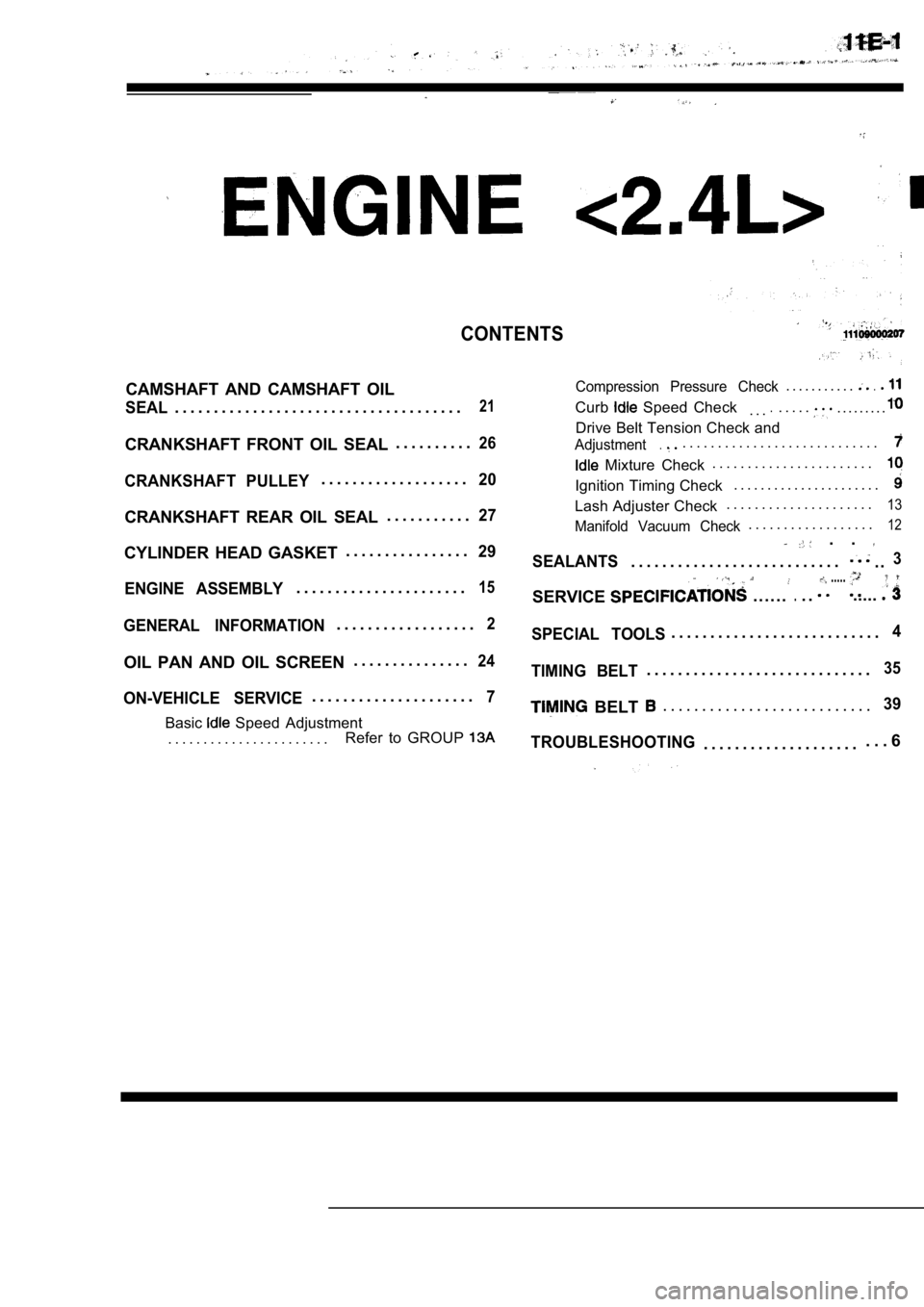
CAMSHAFT AND CAMSHAFT OILCompression Pressure Check. . . . . . . . . . ..
SEAL. . . . . . . . . . . . . . . . . . . . . . . . . . . . . . . . . . . . .21Curb Speed Check. . ... . . . .. . . . . . . . .
Drive Belt Tension Check and
CRANKSHAFT FRONT OIL SEAL. . . . . . . . . .26Adjustment.. . . . . . . . . . . . . . . . . . . . . . . . . . . .
Mixture Check . . . . . . . . . . . . . . . . . . . . . . .
CRANKSHAFT PULLEY. . . . . . . . . . . . . . . . . . .20Ignition Timing Check
. . . . . . . . . . . . . . . . . . . . . .
. . . . . . . . . . . . . . . . . . . . .13CRANKSHAFT REAR OIL SEAL27Lash Adjuster Check
. . . . . . . . . . .
Manifold Vacuum Check. . . . . . . . . . . . . . . . . .12
CYLINDER HEAD GASKET . . . . . . . . . . . . . . . .29 . .
SEALANTS. . . . . . . . . . . . . . . . . . . . . . . . . . .. .3
ENGINE ASSEMBLY. . . . . . . . . . . . . . . . . . . . . .15SERVICE. . . . . ... .
.....
.....
GENERAL INFORMATION. . . . . . . . . . . . . . . . . .2SPECIAL TOOLS. . . . . . . . . . . . . . . . . . . . . . . . . . .4
OIL PAN AND OIL SCREEN . . . . . . . . . . . . . . .24
ON-VEHICLE SERVICE. . . . . . . . . . . . . . . . . . . . .7
Basic Speed Adjustment
. . . . . . . . . . . . . . . . . . . . . . . Refer to GROUP
TIMING BELT. . . . . . . . . . . . . . . . . . . . . . . . . . . . .35
BELT . . . . . . . . . . . . . . . . . . . . . . . . . . .39
TROUBLESHOOTING
. . . . . . . . . . . . . . . . . . . . . . . 6
Page 271 of 2103
ENGINEService
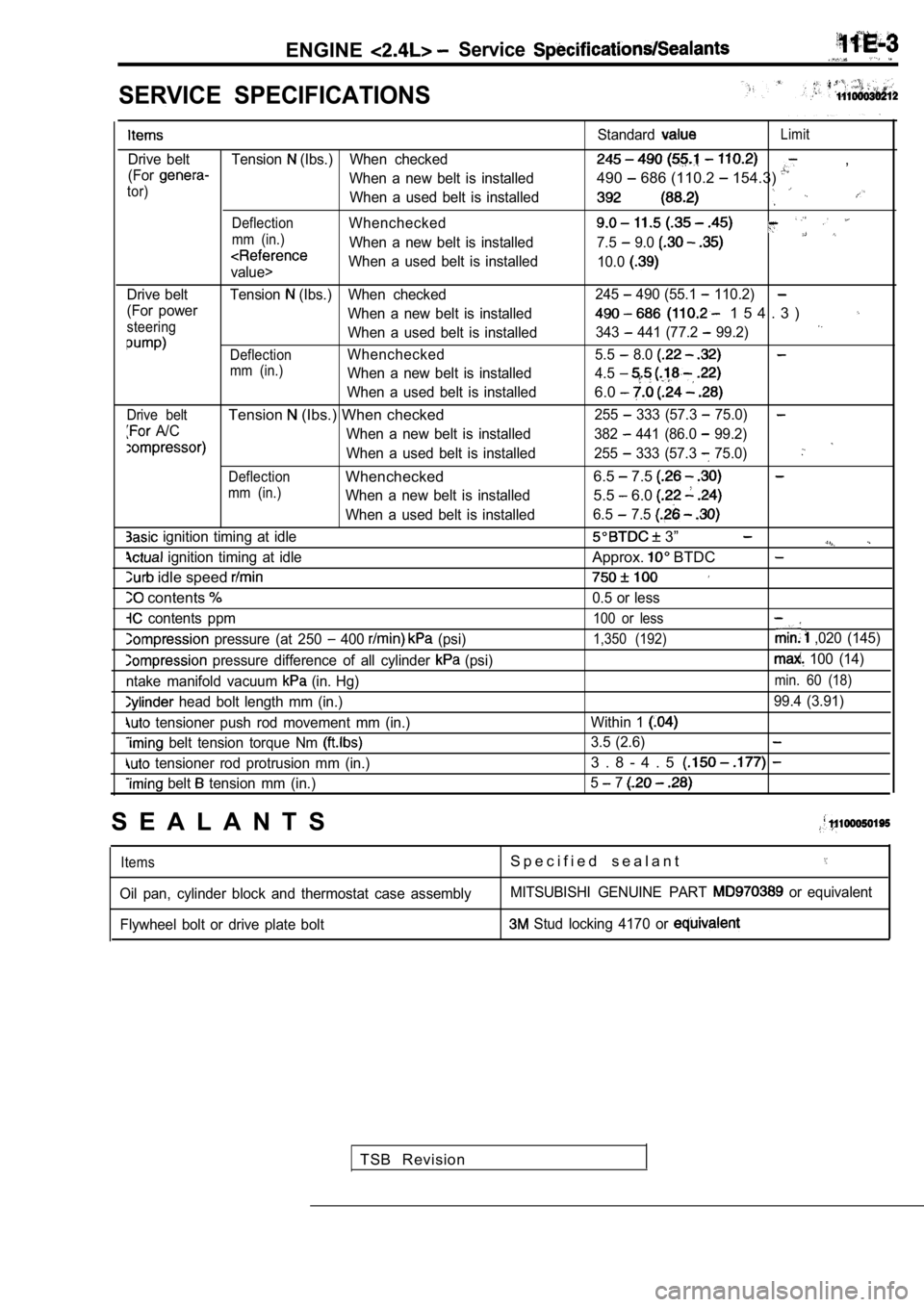
SERVICE SPECIFICATIONS
Drive belt Tension (Ibs.) When checked
(For
When a new belt is installedtor)When a used belt is installed
DeflectionWhenchecked
mm (in.)When a new belt is installed
value> When a used belt is installed
Drive belt Tension
(Ibs.) When checked
(For power When a new belt is installed
steeringWhen a used belt is installed
DeflectionWhenchecked
mm (in.)When a new belt is installed
When a used belt is installed
Drive beltTension (Ibs.) When checked
A/C When a new belt is installed
When a used belt is installed
DeflectionWhenchecked
mm (in.)When a new belt is installed
When a used belt is installed
ignition timing at idle
ignition timing at idle
idle speed
contents
contents ppm
pressure (at 250 400 (psi)
pressure difference of all cylinder (psi)
ntake manifold vacuum
(in. Hg)
head bolt length mm (in.)
tensioner push rod movement mm (in.)
belt tension torque Nm
tensioner rod protrusion mm (in.)
belt tension mm (in.) Standard
Limit
,
490
686 (110.2 154.3)
7.5 9.0
10.0
245 490 (55.1 110.2)
1 5 4 . 3 )
343 441 (77.2 99.2)
5.5 8.0
4.5
6.0
255 333 (57.3 75.0)
382 441 (86.0 99.2)
255
333 (57.3 75.0)
6.5 7.5
5.5 6.0
6.5 7.5
3”
Approx. BTDC
0.5 or less
100 or less
1,350 (192) ,020 (145)
100 (14)
min. 60 (18)
99.4 (3.91)
Within 1
3.5 (2.6)
3 . 8 - 4 . 5
5 7
S E A L A N T S
ItemsS p e c i f i e d s e a l a n t
Oil pan, cylinder block and thermostat case assembl yMITSUBISHI GENUINE PART or equivalent
Flywheel bolt or drive plate bolt
Stud locking 4170 or
TSB Revision