door lock MITSUBISHI SPYDER 1990 Service Repair Manual
[x] Cancel search | Manufacturer: MITSUBISHI, Model Year: 1990, Model line: SPYDER, Model: MITSUBISHI SPYDER 1990Pages: 2103, PDF Size: 68.98 MB
Page 17 of 2103
GENERAL Vehicle
Heat
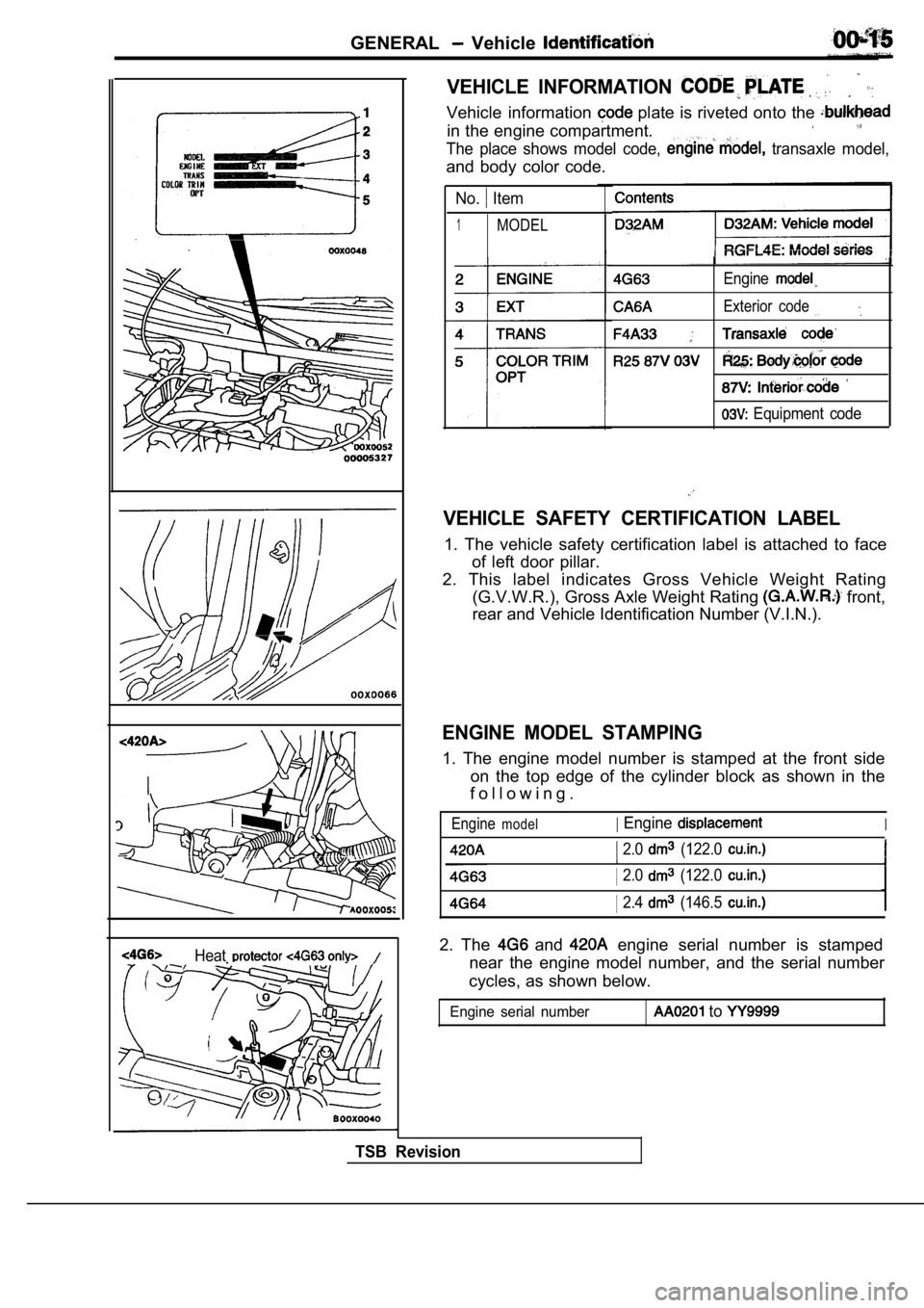
VEHICLE INFORMATION
Vehicle information plate is riveted onto the
in the engine compartment.
The place shows model code, transaxle model,
and body color code.
No. Item
1MODEL
Engine
Exterior code
Equipment code
VEHICLE SAFETY CERTIFICATION LABEL
1. The vehicle safety certification label is attached to face
of left door pillar.
2. This label indicates Gross Vehicle Weight Rating (G.V.W.R.), Gross Axle Weight Rating
front,
rear and Vehicle Identification Number (V.I.N.).
ENGINE MODEL STAMPING
1. The engine model number is stamped at the front side
on the top edge of the cylinder block as shown in t he
f o l l o w i n g .
Enginemodel Engine
2.0 (122.0
I
I 2.0 (122.0
2.4 (146.5
2. The and engine serial number is stamped
near the engine model number, and the serial number
cycles, as shown below.
Engine serial number to
TSB Revision
Page 18 of 2103
GENERAL Vehicle Identification
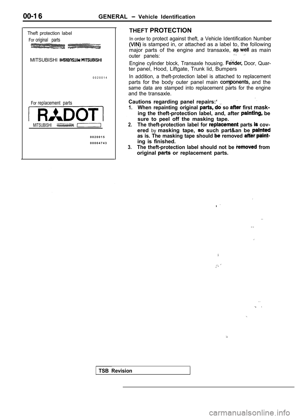
Theft protection label
Fororiginal parts
MITSUBISHI
0 0 2 0 0 1 4
Forreplacement parts
MITSUBISHI
0 0 2 0 0 1 5
0 0 0 0 4 7 4 3THEFT
PROTECTION
In order to protect against theft, a Vehicle Identification Number
is stamped in, or attached as a label to, the foll owing
major parts of the engine and transaxle,
as main
outer panels:
Engine cylinder block, Transaxle housing. Door, Quar-
ter panel, Hood, Liftgate, Trunk lid, Bumpers
In addition, a theft-protection label is attached t o replacement
parts for the body outer panel main and the
same data are stamped into replacement parts for th e engine
and the transaxle.
Cautions regarding panel repairs:‘
1.When repainting original so first mask-
ing the theft-protection label, and, after be
sure to peel off the masking tape.
2.The theft-protection label for parts cov-
ered bymasking tape, such part&an be
as is. The masking tape should removed
ing is finished.
3.The theft-protection label should not be from
original or replacement parts.
,
. .
TSB Revision
Page 25 of 2103
GENERAL Towing and Hoisting
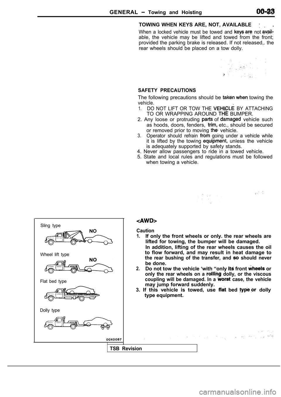
Sling type
Wheel lift type
Flat bed type
Dolly type
TOWING WHEN KEYS ARE, NOT, AVAILABLE .
When a locked vehicle must be towed and not
able, the vehicle may be lifted and towed from the front;
provided the parking brake is released. If not rele ased,. the
rear wheels should be placed on a tow dolly.
SAFETY PRECAUTIONS
The following precautions should be towing the
vehicle.
1.DO NOT LIFT OR TOW THE BY ATTACHING
TO OR WRAPPING AROUND BUMPER.
2. Any loose or protruding
of vehicle such
as hoods, doors, fenders,
etc., should be secured
or removed prior to moving
vehicle.
3.Operator should refrain going under a vehicle while
it is lifted by the towing unless the vehicle
is adequately supported by safety stands.
4. Never allow passengers to ride in a towed vehicl e.
5. State and local rules and regulations must be fo llowed
when towing a vehicle.
Caution
1.If only the front wheels or only. the rear wheels a re
lifted for towing, the bumper will be damaged.
In addition, lifting of the rear wheels causes the oil
to flow forward, and may result in heat damage to
the rear bushing of the transfer, and should never
be done.
2.Do not tow the vehicle ‘with “only front or
only the rear wheels on a dolly, or the viscous
coupling will be damaged. In a
case, the vehicle
may jump forward suddenly.
3. If this vehicle is towed, use
bed dolly
type equipment.
TSB Revision
Page 57 of 2103
GENERAL Main and Adhesive Table
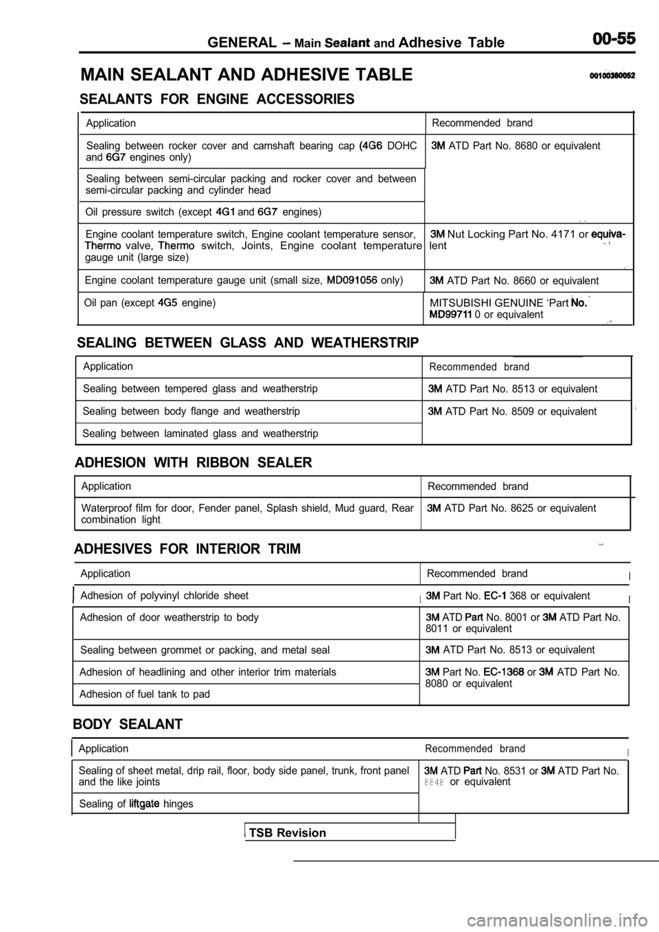
MAIN SEALANT AND ADHESIVE TABLE
SEALANTS FOR ENGINE ACCESSORIES
Application Recommended brand
Sealing between rocker cover and camshaft bearing c ap
DOHC ATD Part No. 8680 or equivalent
and
engines only)
1Sealing between semi-circular packing and rocker co ver and between
semi-circular packing and cylinder head
Oil pressure switch (except
and engines). . .
Engine coolant temperature switch, Engine coolant t emperature sensor, Nut Locking Part No. 4171 or
valve, switch, Joints, Engine coolant temperature lent
gauge unit (large size)
Engine coolant temperature gauge unit (small size, only) ATD Part No. 8660 or equivalent
Oil pan (except
engine)MITSUBISHI GENUINE ‘Part
0 or equivalent
SEALING BETWEEN GLASS AND WEATHERSTRIP
Application
Sealing between tempered glass and weatherstrip
Sealing between body flange and weatherstrip
Sealing between laminated glass and weatherstripRecommended brand
ATD Part No. 8513 or equivalent
ATD Part No. 8509 or equivalent
ADHESION WITH RIBBON SEALER
Application Recommended brand
Waterproof film for door, Fender panel, Splash shie ld, Mud guard, Rear
ATD Part No. 8625 or equivalent
combination light
ADHESIVES FOR INTERIOR TRIM
Application Recommended brandI
Adhesion of polyvinyl chloride sheetI Part No. 368 or equivalentI
Adhesion of door weatherstrip to body ATD No. 8001 or ATD Part No.
8011 or equivalent
Sealing between grommet or packing, and metal seal
Adhesion of headlining and other interior trim mate rials
Adhesion of fuel tank to pad
ATD Part No. 8513 or equivalent
Part No. or ATD Part No.
8080 or equivalent
BODY SEALANT
ApplicationRecommended brandI
Sealing of sheet metal, drip rail, floor, body side panel, trunk, front panel ATD No. 8531 or ATD Part No.
and the like joints8848or equivalent
Sealing of
hinges
TSB Revision
Page 1825 of 2103
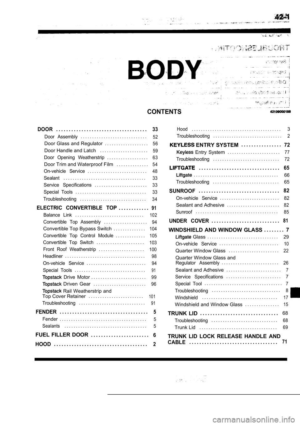
CONTENTS
DOOR. . . . . . . . . . . . . . . . . . . . . . . . . . . . . . . . . . . .33
Door Assembly. . . . . . . . . . . . . . . . . . . . . . . . . . . . .52
Door Glass and Regulator . . . . . . . . . . . . . . . . . . .56
Door Handle and Latch. . . . . . . . . . . . . . . . . . . . .59
Door Opening Weatherstrip. . . . . . . . . . . . . . . . . .63
Door Trim and Waterproof Film . . . . . . . . . . . . . .54
On-vehicle Service. . . . . . . . . . . . . . . . . . . . . . . . . .48
Sealant. . . . . . . . . . . . . . . . . . . . . . . . . . . . . . . . . . . .33
Service Specifications. . . . . . . . . . . . . . . . . . . . . . .33
Special Tools. . . . . . . . . . . . . . . . . . . . . . . . . . . . . . .33
Troubleshooting. . . . . . . . . . . . . . . . . . . . . . . . . . . . .34
ELECTRIC CONVERTIBLE TOP. . . . . . . . . . . .91
Balance Link. . . . . . . . . . . . . . . . . . . . . . . . . . . . . .102
Convertible Top Assembly. . . . . . . . . . . . . . . . . . .94
Convertible Top Bypass Switch . . . . . . . . . . . . . .104
Convertible Top Control Module. . . . . . . . . . . . .105
Convertible Top Switch. . . . . . . . . . . . . . . . . . . . .103
Front Roof Weatherstrip. . . . . . . . . . . . . . . . . . . .100
Headliner. . . . . . . . . . . . . . . . . . . . . . . . . . . . . . . . . . .98
On-vehicle Service. . . . . . . . . . . . . . . . . . . . . . . . . .94
Special Tools. . . . . . . . . . . . . . . . . . . . . . . . . . . . . . .91
Drive Motor. . . . . . . . . . . . . . . . . . . . . . . .99
Driven Gear . . . . . . . . . . . . . . . . . . . . . . .96
Rail Weatherstrip and
Top Cover Retainer . . . . . . . . . . . . . . . . . . . . . . . .
101
Troubleshooting. . . . . . . . . . . . . . . . . . . . . . . . . . . . .91
FENDER. . . . . . . . . . . . . . . . . . . . . . . . . . . . . . . . . . .5
Fender. . . . . . . . . . . . . . . . . . . . . . . . . . . . . . . . . . . . . .5
Sealants
. . . . . . . . . . . . . . . . . . . . . . . . . . . . . . . . . . . .5
FUEL FILLER DOOR . . . . . . . . . . . . . . . . . . . . . . .6
HOOD. . . . . . . . . . . . . . . . . . . . . . . . . . . . . . . . . . . . .2
Hood. . . . . . . . . . . . . . . . . . . . . . . . . . . . . . . . . . . . . . .3
Troubleshooting
. . . . . . . . . . . . . . . . . . . . . . . . . . . . . .2
ENTRY SYSTEM . . . . . . . . . . . . . . . .72
Entry System
. . . . . . . . . . . . . . . . . . . . . . .77
Troubleshooting. . . . . . . . . . . . . . . . . . . . . . . . . . . . .72
. . . . . . . . . . . . . . . . . . . . . . . . . . . . . . . .65
. . . . . . . . . . . . . . . . . . . . . . . . . . . . . . . . . . . . .66
Troubleshooting
. . . . . . . . . . . . . . . . . . . . . . . . . . . . .65
SUNROOF. . . . . . . . . . . . . . . . . . . . . . . . . . . . . . . .82
On-vehicle Service. . . . . . . . . . . . . . . . . . . . . . . . . .82
Sealant and Adhesive . . . . . . . . . . . . . . . . . . . . . . .82
Sunroof. . . . . . . . . . . . . . . . . . . . . . . . . . . . . . . . . . . .85
UNDER COVER. . . . . . . . . . . . . . . . . . . . . . . . . . .81
WINDSHIELD AND WINDOW GLASS . . . . . . . .
7
Glass. . . . . . . . . . . . . . . . . . . . . . . . . . . . . . .29
On-vehicle Service
. . . . . . . . . . . . . . . . . . . . . . . . . .10
Quarter Window Glass . . . . . . . . . . . . . . . . . . . . . .22
Quarter Window Glass and
Regulator Assembly. . . . . . . . . . . . . . . . . . . . . . . . .26
Sealant and Adhesive. . . . . . . . . . . . . . . . . . . . . . . .7
Service Specifications. . . . . . . . . . . . . . . . . . . . . . . .7
Special Tool
. . . . . . . . . . . . . . . . . . . . . . . . . . . . . . . . . .7
Troubleshooting. . . . . . . . . . . . . . . . . . . . . . . . . . . . . .8
Windshield. . . . . . . . . . . . . . . . . . . . . . . . . . . . . . . . .17
Windshield and Window Glass . . . . . . . . . . . . . . .15
TRUNK LID. . . . . . . . . . . . . . . . . . . . . . . . . . . . . . . 68
Troubleshooting. . . . . . . . . . . . . . . . . . . . . . . . . . . . .68
Trunk Lid
. . . . . . . . . . . . . . . . . . . . . . . . . . . . . . . . . .69
TRUNK LID LOCK RELEASE HANDLE AND
CABLE. . . . . . . . . . . . . . . . . . . . . . . . . . . . . . . . . . .71
Page 1830 of 2103
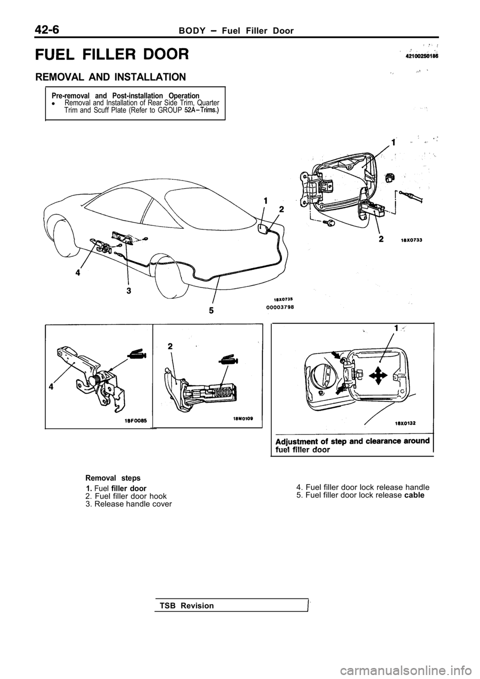
B O D Y Fuel Filler Door
REMOVAL AND INSTALLATION
Pre-removal and Post-installation OperationlRemoval and Installation of Rear Side Trim, Quarter
Trim and Scuff Plate (Refer to GROUP
fuel filler door
Removal steps
1.
Fuelfiller door2. Fuel filler door hook3. Release handle cover 4. Fuel filler door lock release handle
5. Fuel filler door lock release
cable
TSB Revision
Page 1834 of 2103
BODY Windshield and Window Glass
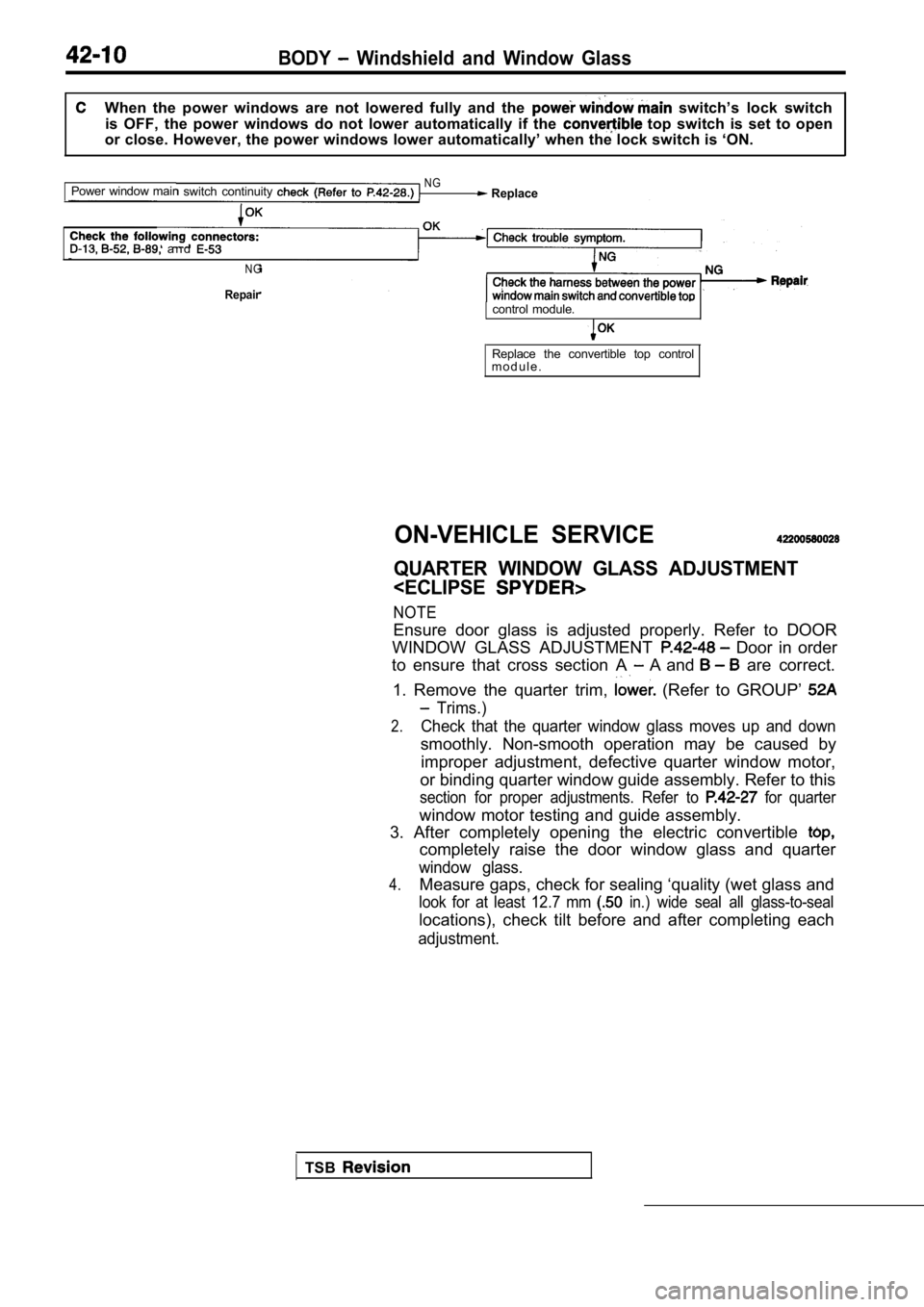
When the power windows are not lowered fully and the switch’s lock switch
is OFF, the power windows do not lower automaticall y if the
top switch is set to open
or close. However, the power windows lower automati cally’ when the lock switch is ‘ON.
Power window mair
switch continuity NG Replace
a n d
N G
Repaircontrol module.
Replace the convertible top control
m o d u l e .
ON-VEHICLE SERVICE
QUARTER WINDOW GLASS ADJUSTMENT
Ensure door glass is adjusted properly. Refer to DO OR
WINDOW GLASS ADJUSTMENT
Door in order
to ensure that cross section A
A and are correct.
1. Remove the quarter trim,
(Refer to GROUP’
Trims.)
2.Check that the quarter window glass moves up and do wn
smoothly. Non-smooth operation may be caused by
improper adjustment, defective quarter window motor ,
or binding quarter window guide assembly. Refer to this
section for proper adjustments. Refer to for quarter
window motor testing and guide assembly.
3. After completely opening the electric convertibl e
completely raise the door window glass and quarter
window glass.
4.Measure gaps, check for sealing ‘quality (wet glass and
look for at least 12.7 mm in.) wide seal all glass-to-seal
locations), check tilt before and after completing each
adjustment.
TSB
Page 1859 of 2103
‘ D o o r.
‘I-
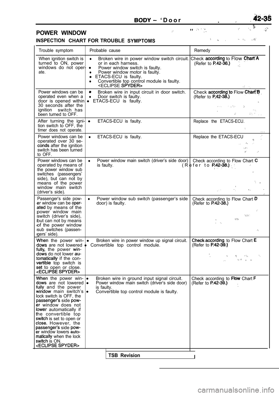
POWER WINDOW
,,
INSPECTIONCHART FOR TROUBLESYMPTOMS
Trouble symptom Probable causeRemedy
When ignition switch is
lturned to ON, power Broken wire in power window switch circuit. Check to
Flowor in each harness.(Refer to windows do not oper- l
Power window switch is faulty.ate.lPower window motor is faulty.
l ETACS-ECU is faulty.
lConvertible top control module is faulty.
l ETACS-ECU is faulty.30 seconds after theignitionswitch hasbeen turned to OFF.
After turning the igni- lETACS-ECU is faulty.Replace the ETACS-ECU.tion switch to OFF, thetimer does not operate. . .
Power windows can belETACS-ECU is faulty. Replace the ETACS-ECUoperated over 30 se- after the ignitionswitch has been turnedto OFF.
Power windows can belPower window main switch (driver’s side door)
Check according to Flow Chart operated by means ofis faulty.
the power window sub( R e f e r t o
switches (passengers’side), but can not by
means of the power ,
window main switch
(driver’s side).
Passenger’s side pow-lPower window sub switch (passenger’s sideCheck according to Flow Chart window can be (Refer to by means of the door) is faulty.
power window main
switch (driver’s side),but can not by meansof the power windowsub switches (passen-gers’ side).
the power win- lBroken wire in power window up signal circuit. to Flow Chart are not lowered l Convertible top control module.(Refer to the power do not lower if the con-‘.
top switch is to open or close.
the power win- l
Broken wire in ground input signal circuit.Check according to Chart are not lowered lPower window main switch (driver’s side door)
(Refer to and the poweris faulty. main switch’s l
Convertible top control module is faulty.ock switch is OFF, the side window does not automatically if
he convertible top
is set to open or However, the side window lowers when the lock
is ON.
TSB RevisionI
Page 1863 of 2103
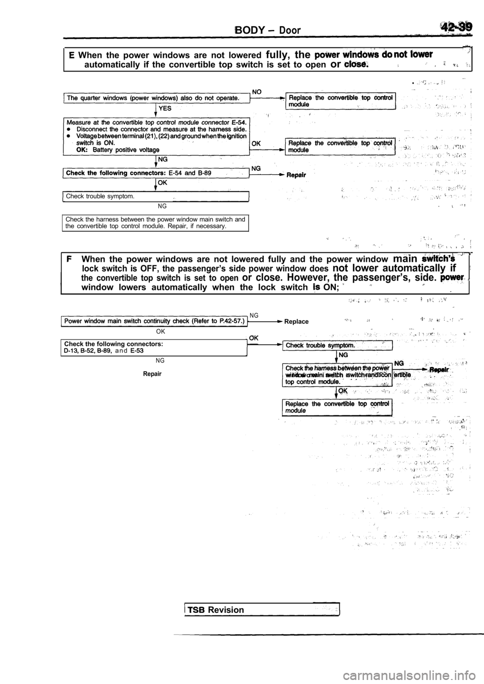
BODYDoor
When the power windows are not lowered fully, the
automatically if the convertible top switch is set to open or
.
Check trouble symptom.
NG.
Check the harness between the power window main swi tch and
the convertible top control module. Repair, if nece ssary.
,
When the power windows are not lowered fully and th e power window main
lock switch is OFF, the passenger’s side power wind ow does not lower automatically if
the convertible top switch is set to open or close. However, the passenger’s, side.
window lowers automatically when the lock switch ON;
N G Replace
OK .
Check the following connectors: a n d
N G
Repairw i n d o w i n a i n .
Revision
Page 1864 of 2103
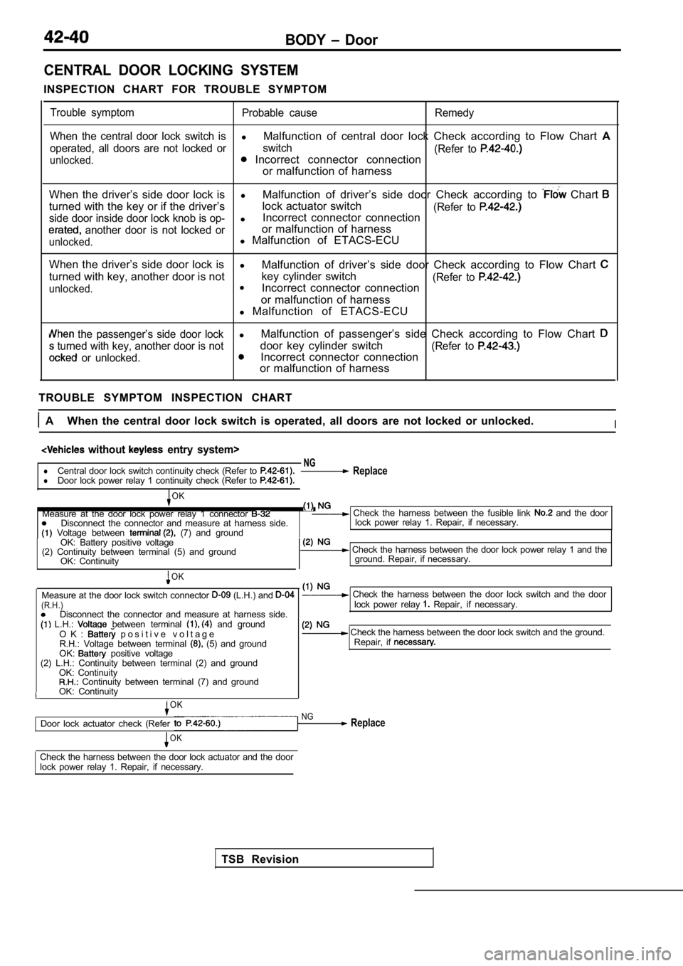
BODY Door
CENTRAL DOOR LOCKING SYSTEM
INSPECTION CHART FOR TROUBLE SYMPTOM
Trouble symptom Probable cause Remedy
When the central door lock switch is
l Malfunction of central door lock Check according to Flow Chart A
operated, all doors are not locked or switch
(Refer to
unlocked. Incorrect connector connection
or malfunction of harness
When the driver’s side door lock is lMalfunction of driver’s side door Check according t o
Chart
turned with the key or if the driver’slock actuator switch(Refer to side door inside door lock knob is op-lIncorrect connector connection
another door is not locked oror malfunction of harness
unlocked.l
Malfunction of ETACS-ECU
When the driver’s side door lock is l
Malfunction of driver’s side door Check according t o Flow Chart
turned with key, another door is notkey cylinder switch(Refer to
unlocked.l
Incorrect connector connection
or malfunction of harness
l Malfunction of ETACS-ECU
the passenger’s side door lockl Malfunction of passenger’s side Check according to
Flow Chart
turned with key, another door is notdoor key cylinder switch(Refer to
or unlocked.Incorrect connector connection
or malfunction of harness
TROUBLE SYMPTOM INSPECTION CHART
A When the central door lock switch is operated, al l doors are not locked or unlocked.I
without entry system>
NGlCentral door lock switch continuity check (Refer to ReplacelDoor lock power relay 1 continuity check (Refer to
TSB Revision
OK
Measure at the door lock power relay 1 connector Check the harness between the fusible link and the door
Disconnect the connector and measure at harness sid e.
Voltage between (7) and groundlock power relay 1. Repair, if necessary.
OK: Battery positive voltage
(2) Continuity between terminal (5) and ground OK: Continuity
OK
Measure at the door lock switch connector (L.H.) and (R.H.)Disconnect the connector and measure at harness sid e. L.H.: between terminal and groundO K : p o s i t i v e v o l t a g eR.H.: Voltage between terminal (5) and ground
OK: positive voltage
(2) L.H.: Continuity between terminal (2) and groun d
OK: Continuity
Continuity between terminal (7) and ground
OK: Continuity
OK
Door lock actuator check (Refer
OK
Check the harness between the door lock power rela y 1 and the
ground. Repair, if necessary.
Check the harness between the door lock switch and the door
lock power relay Repair, if necessary.
Check the harness between the door lock switch and the ground.
Repair, if
NG Replace
Check the harness between the door lock actuator an d the door
lock power relay 1. Repair, if necessary.