timing belt MITSUBISHI SPYDER 1990 Service Owner's Manual
[x] Cancel search | Manufacturer: MITSUBISHI, Model Year: 1990, Model line: SPYDER, Model: MITSUBISHI SPYDER 1990Pages: 2103, PDF Size: 68.98 MB
Page 117 of 2103
ENGINE OVERHAUL
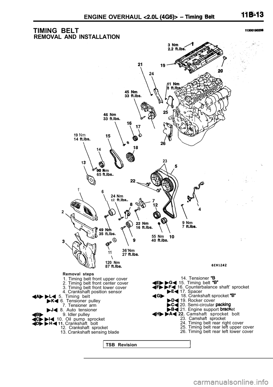
TIMING BELT
REMOVAL AND INSTALLATION
19N m
24
14
14
13
90 Nm65
23
1624 Nm17
24
9 Nm7
.1136 Nm27
120 Nm87
Removal steps
1. Timing belt front upper cover
2. Timing belt front center cover
3. Timing belt front lower cover
4. Crankshaft position sensor
5. Timing belt 6. Tensioner pulley7. Tensioner arm 8. Auto tensioner
9. Idler pulley
10. Oil pump sprocket 11. Crankshaft bolt12. Crankshaft sprocket13. Crankshaft sensing blade
55 Nm40
14. Tensioner 15. Timing belt 16. Counterbalance shaft’ sprocket 17. Spacer18. Crankshaft sprocket
19. Rocker cover 20. Semi-circular
21. Engine support et
22. Camshaft sprocket bolt23. Camshaft sprocket24. Timing belt rear right cover
25. Timing belt rear left upper cover
26. Timing belt rear left lower cover
TSB Revision
Page 118 of 2103
OVERHAUL Timing. Belt
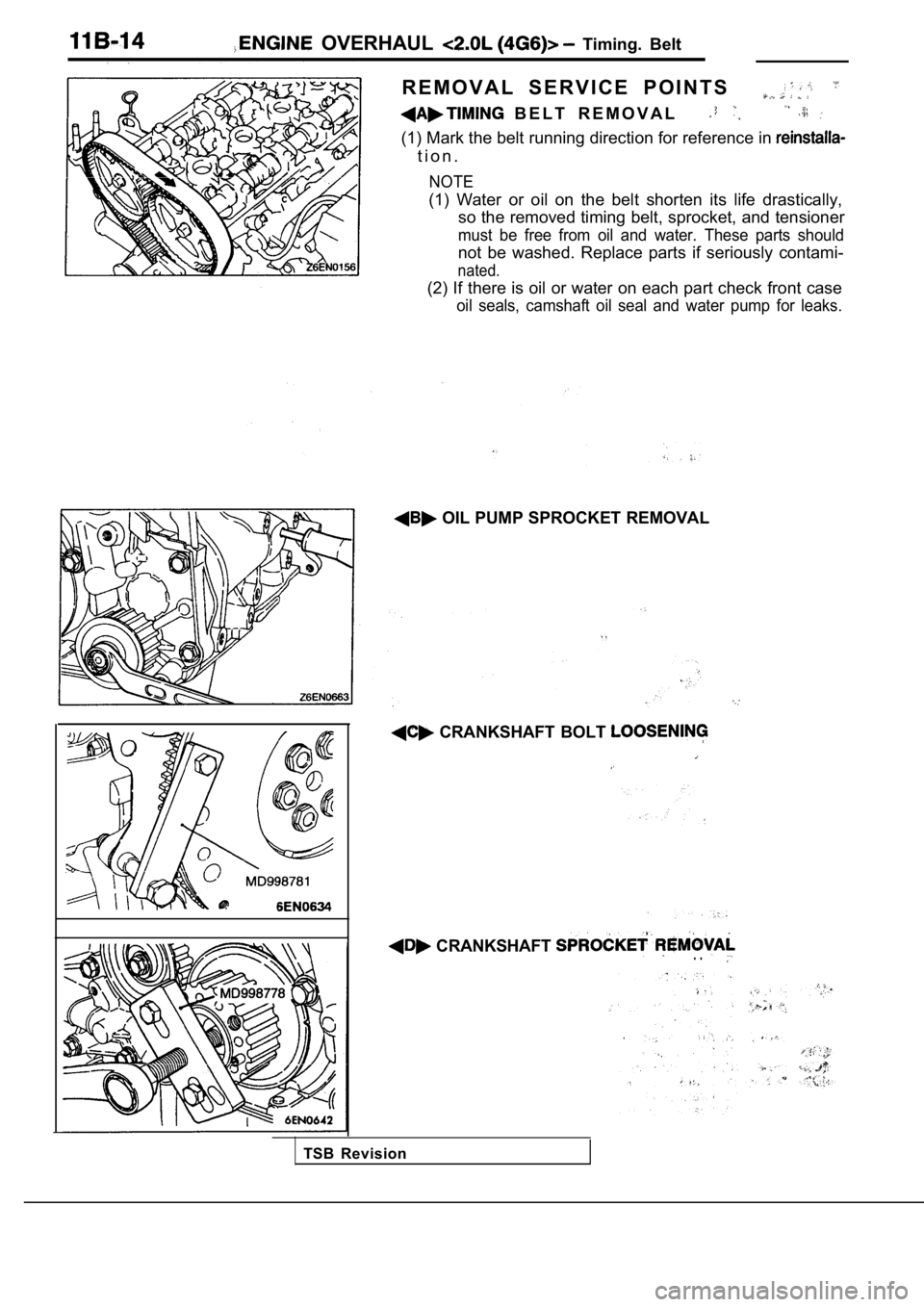
R E M O V A L S E R V I C E P O I N T S
B E L T R E M O V A L
(1) Mark the belt running direction for reference in
t i o n .
NOTE
(1) Water or oil on the belt shorten its life drast ically,
so the removed timing belt, sprocket, and tensioner
must be free from oil and water. These parts should
not be washed. Replace parts if seriously contami-
nated.
(2) If there is oil or water on each part check fro nt case
oil seals, camshaft oil seal and water pump for lea ks.
OIL PUMP SPROCKET REMOVAL
CRANKSHAFT BOLT
CRANKSHAFT . .
TSB Revision
Page 119 of 2103
OVERHAUL Timing
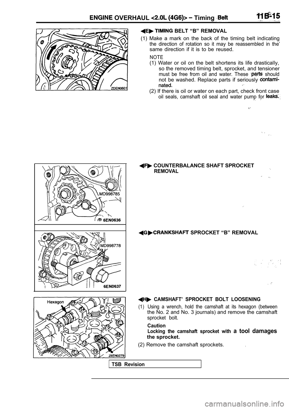
BELT “B” REMOVAL
(1) Make a mark on the back of the timing belt indi cating
the direction of rotation so it may be reassembled in the’
same direction if it is to be reused.
NOTE
(1) Water or oil on the belt shortens its life drastically,
so the removed timing belt, sprocket, and tensioner
must be free from oil and water. These should
not be washed. Replace parts if seriously
(2) If there is oil or water on each part, check fr ont case
oil seals, camshaft oil seal and water pump for
COUNTERBALANCE SHAFT SPROCKET
REMOVAL
SPROCKET “B” REMOVAL
CAMSHAFT’ SPROCKET BOLT LOOSENING
(1)Using a wrench, hold the camshaft at its hexagon (b etween
the No. 2 and No. 3 journals) and remove the camshaft
sprocket bolt.
Caution
Locking the camshaft sprocket with a tool damages
the sprocket.
(2) Remove the camshaft sprockets.
,
TSB Revision
Page 120 of 2103
ENGINE OVERHAUL Timing Belt,
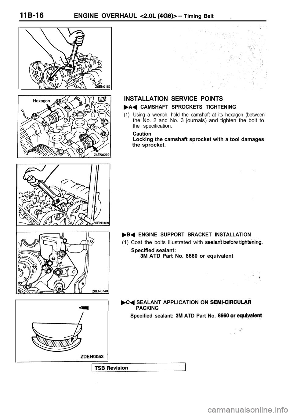
INSTALLATION SERVICE POINTS
CAMSHAFT SPROCKETS TIGHTENING
(1)Using a wrench, hold the camshaft at its hexagon (between
the No. 2 and No. 3 journals) and tighten the bolt to
the specification.
Caution
Locking the camshaft sprocket with a tool damages
the sprocket.
ENGINE SUPPORT BRACKET INSTALLATION
(1) Coat the bolts illustrated with
Specified sealant:
ATD Part No. 8660 or equivalent
SEALANT APPLICATION ON
PACKING
Specified sealant:
ATD Part No.
Page 121 of 2103
ENGINE OVERHAUL Timing Belt
Semi-circularCylinder head
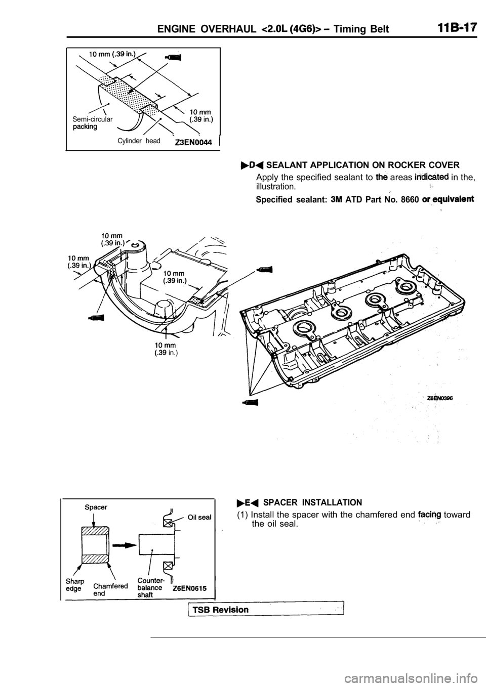
SEALANT APPLICATION ON ROCKER COVER
Apply the specified sealant to
areas in the,
illustration.
Specified sealant: ATD Part No. 8660
in.)
SPACER INSTALLATION
(1) Install the spacer with the chamfered end toward
the oil seal.
Page 122 of 2103
ENGINE OVERHAUL Timing’
COUNTERBALANCE SHAFT
INSTALLATION
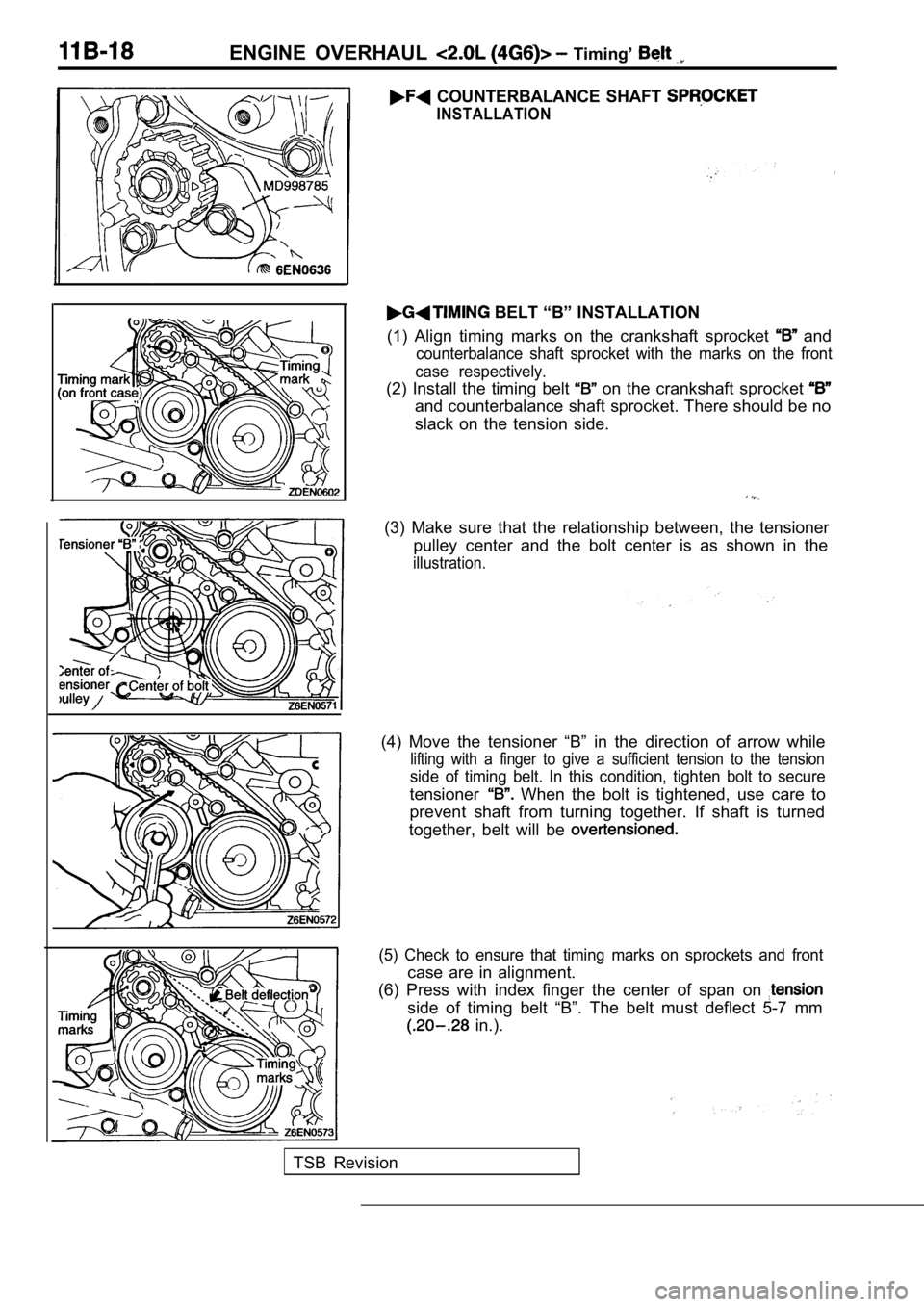
BELT “B” INSTALLATION
(1) Align timing marks on the crankshaft sprocket
and
counterbalance shaft sprocket with the marks on the front
case respectively.
(2) Install the timing belt on the crankshaft sprocket
and counterbalance shaft sprocket. There should be no
slack on the tension side.
(3) Make sure that the relationship between, the te nsioner
pulley center and the bolt center is as shown in th e
illustration.
(4) Move the tensioner “B” in the direction of arrow while
lifting with a finger to give a sufficient tension to the tension
side of timing belt. In this condition, tighten bolt to secure
tensioner When the bolt is tightened, use care to
prevent shaft from turning together. If shaft is tu rned
together, belt will be
(5) Check to ensure that timing marks on sprockets and front
case are in alignment.
(6) Press with index finger the center of span on
side of timing belt “B”. The belt must deflect 5-7 mm
in.).
TSB Revision
Page 124 of 2103
ENGINE OVERHAUL
TENSIONER PULLEY INSTALLATION
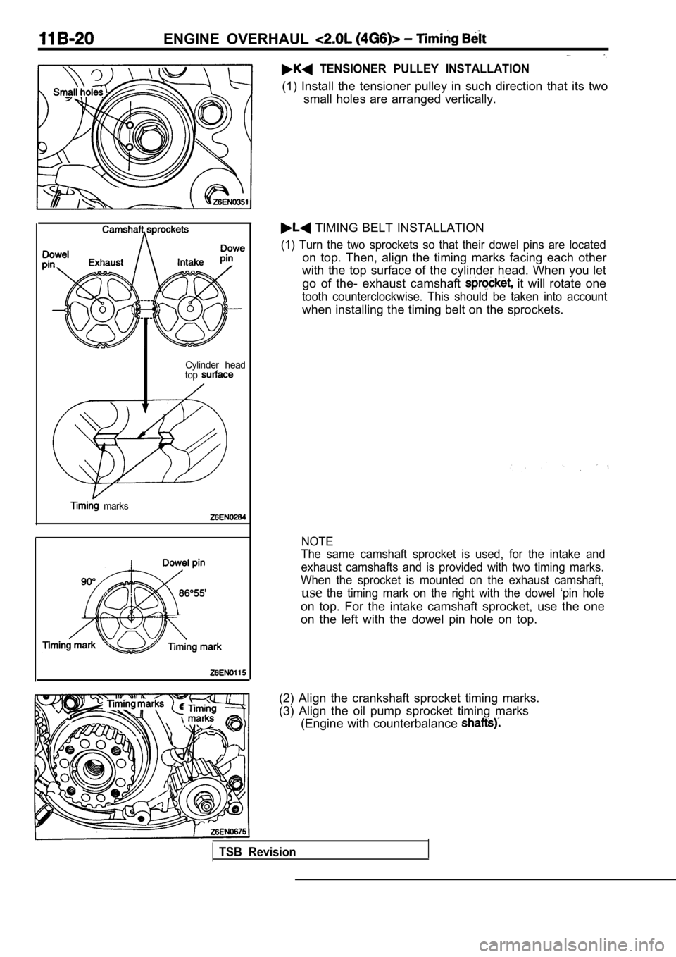
(1) Install the tensioner pulley in such direction that its two
small holes are arranged vertically.
Cylinder head
top
marks
TIMING BELT INSTALLATION
(1) Turn the two sprockets so that their dowel pins are located
on top. Then, align the timing marks facing each ot her
with the top surface of the cylinder head. When you let
go of the- exhaust camshaft
it will rotate one
tooth counterclockwise. This should be taken into a ccount
when installing the timing belt on the sprockets.
NOTE
The same camshaft sprocket is used, for the intake and
exhaust camshafts and is provided with two timing m arks.
When the sprocket is mounted on the exhaust camshaf t,
usethe timing mark on the right with the dowel ‘pin hole
on top. For the intake camshaft sprocket, use the o ne
on the left with the dowel pin hole on top.
(2) Align the crankshaft sprocket timing marks.
(3) Align the oil pump sprocket timing marks (Engine with counterbalance
TSB Revision
Page 125 of 2103
![MITSUBISHI SPYDER 1990 Service Owners Manual ENGINE OVERHAUL Belt
Phillips screwdriver
TSBRevision
(4) a Phillips screwdriver [shank diameter 8 mm
in.)] through the hole.
If it can be inserted as deep as 60 mm (2.4 or](/img/19/57345/w960_57345-124.png "MITSUBISHI SPYDER 1990 Service Owners Manual ENGINE OVERHAUL Belt
Phillips screwdriver
TSBRevision
(4) a Phillips screwdriver [shank diameter 8 mm
in.)] through the hole.
If it can be inserted as deep as 60 mm (2.4 or")
ENGINE OVERHAUL Belt
Phillips screwdriver
TSBRevision
(4) a Phillips screwdriver [shank diameter 8 mm
in.)] through the hole.
If it can be inserted as deep as 60 mm (2.4 or more;
the timing ‘marks are correctly aligned. If the inserted
depth is only
mm in.), turn the oil’ pump
sprocket one turn and
marks. Then check
to ensure that the screwdriver can be inserted 60 m m
(2.4 in.) or more. Keep the screwdriver inserted the
installation of the timing belt is finished.
NOTE
Step (4) is performed to ensure that the oil pump sprocket
is correctly positioned with reference to the counterbal-
ance shafts.
(5) Thread the timing belt over the intake side cam shaft
sprocket and fix it at indicated position by a bulldog clip.
(6) Thread the timing belt over the exhaust side sp rocket,
aligning the timing marks with the cylinder head top surface
using two wrenches.
(7) Fix the belt at indicated, position
a bulldog clip.
Page 126 of 2103
ENGINE OVERHAUL Timing
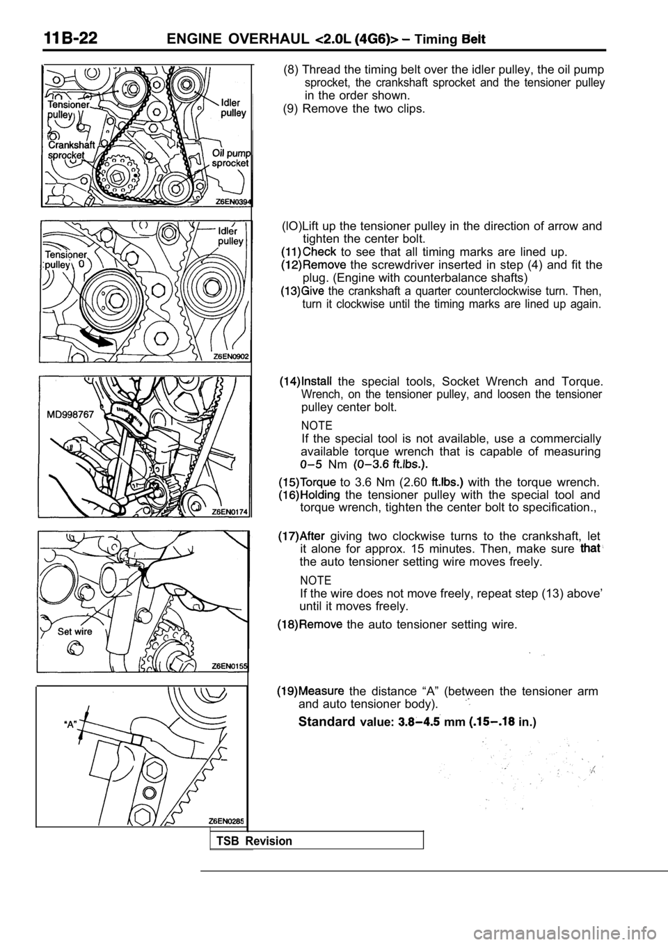
(8) Thread the timing belt over the idler pulley, the oil pump
sprocket, the crankshaft sprocket and the tensioner pulley
in the order shown.
(9) Remove the two clips.
(lO)Lift up the tensioner pulley in the direction o f arrow and
tighten the center bolt.
to see that all timing marks are lined up.
the screwdriver inserted in step (4) and fit the
plug. (Engine with counterbalance shafts)
the crankshaft a quarter counterclockwise turn. Th en,
turn it clockwise until the timing marks are lined up again.
the special tools, Socket Wrench and Torque.
Wrench, on the tensioner pulley, and loosen the ten sioner
pulley center bolt.
NOTE
If the special tool is not available, use a commercially
available torque wrench that is capable of measurin g
Nm
to 3.6 Nm (2.60 with the torque wrench.
the tensioner pulley with the special tool and
torque wrench, tighten the center bolt to specifica tion.,
giving two clockwise turns to the crankshaft, let
it alone for approx. 15 minutes. Then, make sure
the auto tensioner setting wire moves freely.
NOTE
If the wire does not move freely, repeat step (13) above’
until it moves freely.
the auto tensioner setting wire.
the distance “A” (between the tensioner arm
and auto tensioner body).
Standard value: mm in.)
TSB Revision
Page 127 of 2103

ENGINE OVERHAUL Timing
Cracks’
Rounded edgeI
Abnormal wear(Fluffy strand)
Rubber exposed
Tooth missingand canvas fibe
INSPECTION
TIMING BELT
Replace belt if any of the following conditions exi st.
(1) Hardening of back rubber.
Back side is glossy without resilience and leaves no indent
when pressed with fingernail.
(2) Cracks on rubber back.
(3) Cracks or peeling of canvas.
(4) Cracks on rib root.
(5) Cracks on belt sides.
(6) Abnormal wear of belt sides. The sides are norm al if
they are sharp as if cut by a knife.
(7) Abnormal wear on teeth.
(8) Missing tooth.
AUTO TENSIONER
(1) Check the auto tensioner for possible leaks and replace
as necessary.
(2) Check the rod end for wear or damage and replac e as
necessary.
(3) Measure the rod protrusion. If it is out of specification,
replace the auto tensioner.
Standard value: 12 mm
in.)