fuel type MITSUBISHI SPYDER 1990 Service User Guide
[x] Cancel search | Manufacturer: MITSUBISHI, Model Year: 1990, Model line: SPYDER, Model: MITSUBISHI SPYDER 1990Pages: 2103, PDF Size: 68.98 MB
Page 520 of 2103
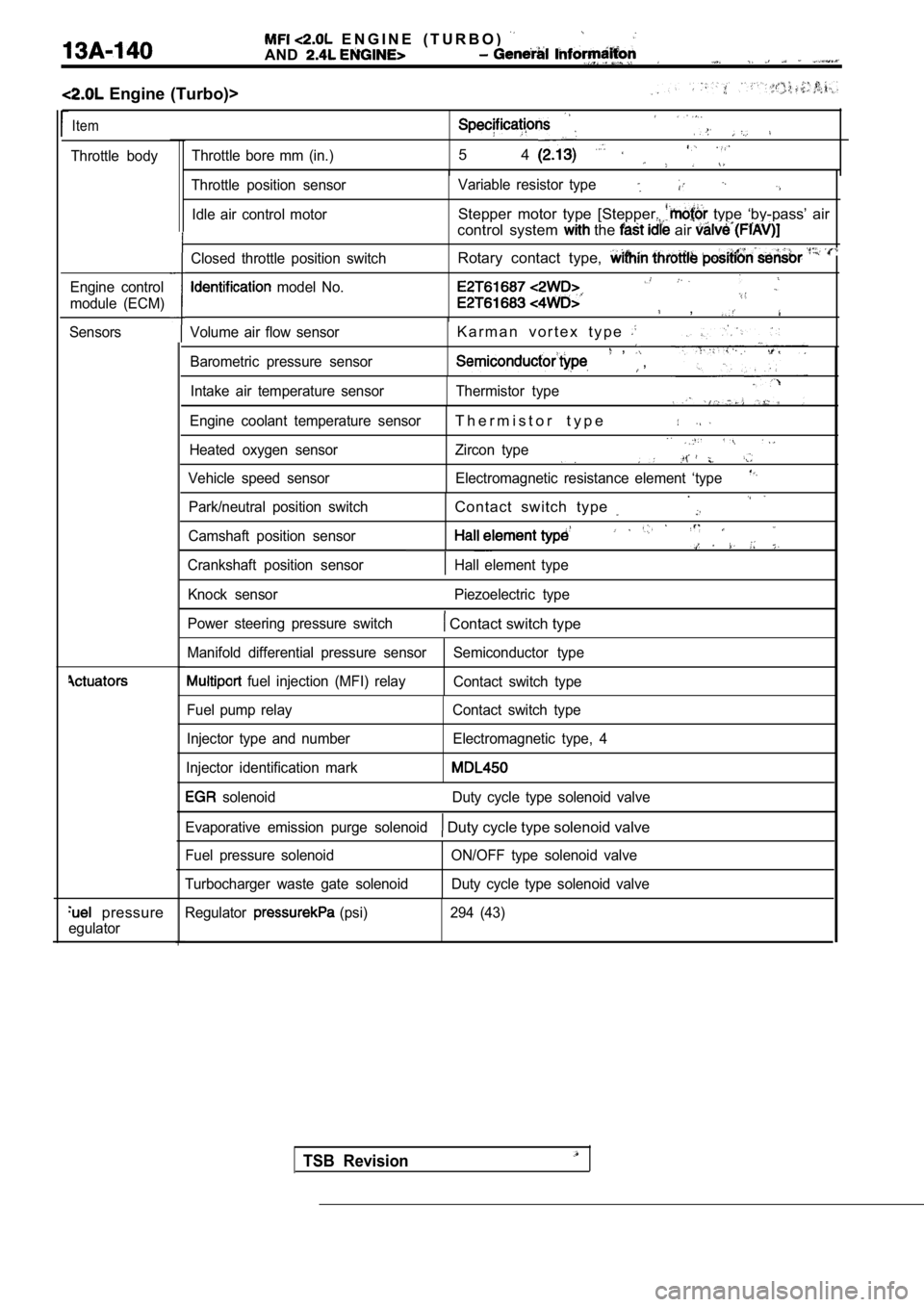
E N G I N E ( T U R B O )
AND
Engine (Turbo)>
Item
Throttle bodyThrottle bore mm (in.)5 4
Engine control
module (ECM)
Sensors
pressure
egulator
Volume air flow sensor
Barometric pressure sensorK a r m a n v o r t e x t y p e , ,
Intake air temperature sensor Thermistor type
Engine coolant temperature sensor
T h e r m i s t o r t y p e
Heated oxygen sensor Zircon type
Vehicle speed sensor Electromagnetic resistance elem ent ‘type
Park/neutral position switchContact switch type .
Camshaft position sensor
Crankshaft position sensorHall element type
Throttle position sensor
Idle air control motor Variable resistor type
Stepper motor type [Stepper. type ‘by-pass’ air
control system
the air
Closed throttle position switch
model No.
Rotary contact type,
,
Knock sensor Piezoelectric type
Power steering pressure switch
Contact switch type
Manifold differential pressure sensor Semiconductor type
fuel injection (MFI) relay
Contact switch type
Fuel pump relay
Injector type and number
Injector identification mark Contact switch type
Electromagnetic type, 4
solenoid Duty cycle type solenoid valve
Evaporative emission purge solenoid
Duty cycle type solenoid valve
Fuel pressure solenoid
Turbocharger waste gate solenoid ON/OFF type solenoid valve
Duty cycle type solenoid valve
Regulator
(psi) 294 (43)
TSB Revision
Page 521 of 2103
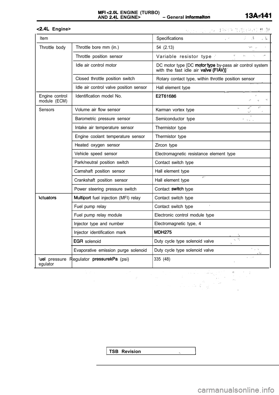
ENGINE (TURBO)
AND
ENGINE> General
Engine>
ItemSpecifications
Throttle body Throttle bore mm (in.)54 (2.13)
Throttle position sensorV a r i a b l e r e s i s t o r t y p e
Idle air control motor
DC motor type [DC by-pass air control system
with the fast idle air
Closed throttle position switch
Rotary contact type, within throttle position senso r
Idle air control valve position sensor
Hall element type
Engine control Identification model No.
module (ECM)
SensorsVolume air flow sensor Karman vortex type
Barometric pressure sensorSemiconductor type.
Intake air temperature sensorThermistor type
Engine coolant temperature sensor Thermistor type
Heated oxygen sensor Zircon type
Vehicle speed sensor Electromagnetic resistance element type
Park/neutral position switch Contact switch type
Camshaft position sensor Hall element type
Crankshaft position sensor Hall element type
Power steering pressure switch Contact type
fuel injection (MFI) relay Contact switch type
Fuel pump relay Contact switch type
Fuel pump relay module Electronic control module typ e
Injector type and number Electromagnetic type, 4
Injector identification mark
,
solenoid Duty cycle type solenoid valve
Evaporative emission purge solenoid
Duty cycle type solenoid valve
pressure Regulator (psi)335 (48)
egulator
TSB Revision
Page 608 of 2103
ENGINE (TURBO)
AND ENGINE> Troubleshooting
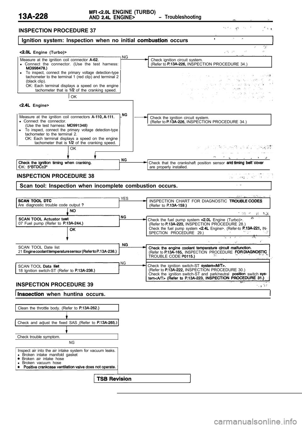
INSPECTION PROCEDURE 37 ,
Ignition system: Inspection when no initial occurs,
Engine (Turbo)> NGMeasure at the ignition coil connector Check ignition circuit system.
l Connect the connector. (Use the test harness:
(Refer to INSPECTION PROCEDURE 34.)
lTo inspect, connect the primary voltage detection-typetachometer to the terminal 1 (red clip) and terminal 2
(black clip).
OK: Each terminal displays a speed on the engine tachometer that is
of the cranking speed.
OK
Engine>
Measure at the ignition coil connectors
l Connect the connector.
(Use the test harness:
lTo inspect, connect the primary voltage detection-t ypetachometer to the terminal 2.OK: Each terminal displays a speed on the engine
tachometer that is of the cranking speed.
OK
NGCheck the ignition circuit system.(Refer to INSPECTION PROCEDURE 34.)
OK:
NG Check that the crankshaft position sensor are properly installed.
INSPECTION PROCEDURE 38
Scan tool: Inspection when incomplete combustion oc curs.
YESINSPECTION CHART FOR DIAGNOSTIC Arediagnostic trouble code output (Refer to
SCAN TOOL Actuator te
07 Fuel pump (Refer toNG, Check the fuel pump system Engine (Turbo)>.(Refer to INSPECTION PROCEDURE 28.)Check the fuel pump system Engine>. (Refer-to IN-
SPECTION PROCEDURE 29.)
./I,’
SCAN TOOL Date list21(Refer to INSPECTION PROCEDURE TROUBLE CODE
NGSCAN TOOL Data Check the ignition switch-ST 18 Ignition switch-ST (Refer to (Refer to INSPECTION PROCEDURE 30.)
Check the ignition switch-ST andpark/neutralswitch
INSPECTION PROCEDURE 39 ,
when huntina occurs.
Clean the throttle body. (Refer to
I
Check and adiust the fixed SAS (Refer to
Check trouble symptom.
NG
Inspect air into the air intake system for vacuum l eaks.
l Broken intake manifold gasket
Broken air intake hose
l Broken vacuum hose
Page 651 of 2103
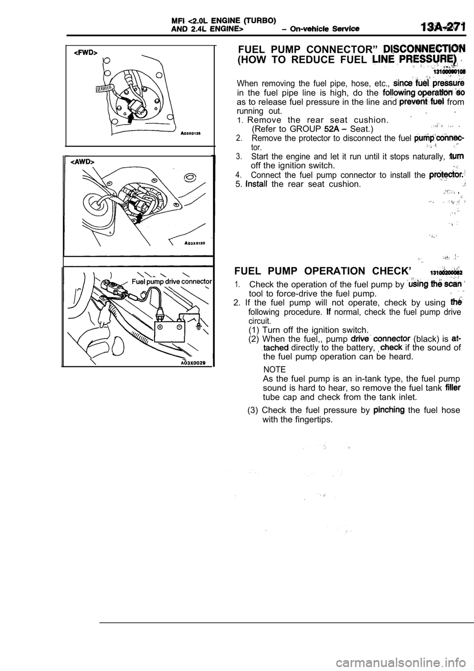
FUEL PUMP CONNECTOR”
(HOW TO REDUCE FUEL
When removing the fuel pipe, hose, etc.,
in the fuel pipe line is high, do the
as to release fuel pressure in the line and from
running out.
1.Remove the rear seat cushion.
(Refer to GROUP Seat.)
2.Remove the protector to disconnect the fuel
tor.
3.Start the engine and let it run until it stops natu rally,
off the ignition switch..
4.Connect the fuel pump connector to install the
5. the rear seat cushion. ,
FUEL PUMP OPERATION CHECK’
1.Check the operation of the fuel pump by
tool to force-drive the fuel pump.
2. If the fuel pump will not operate, check by usin g
following procedure. normal, check the fuel pump drive
circuit.
(1) Turn off the ignition switch.
(2) When the fuel,, pump
(black) is
directly to the battery, if the sound of
the fuel pump operation can be heard.
NOTE
As the fuel pump is an in-tank type, the fuel pump
sound is hard to hear, so remove the fuel tank
tube cap and check from the tank inlet.
(3) Check the fuel pressure by
the fuel hose
with the fingertips.
Page 678 of 2103
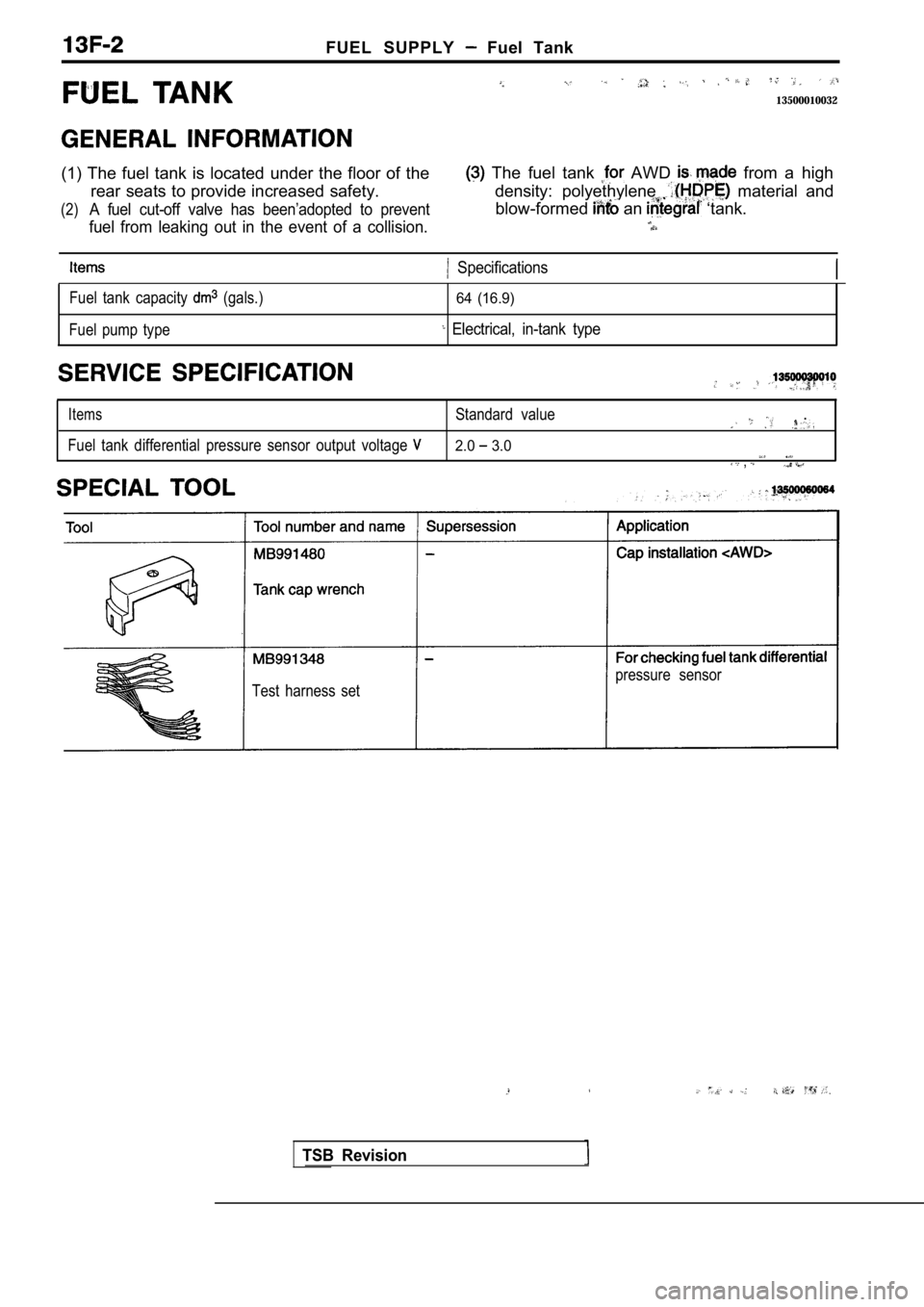
FUEL SUPPLY Fuel Tank
13500010032
(1) The fuel tank is located under the floor of the The fuel tank AWD from a high
rear seats to provide increased safety. density: pol yethylene
material and
(2)A fuel cut-off valve has been’adopted to preventblow-formed an ‘tank.
fuel from leaking out in the event of a collision.
Specifications
Fuel tank capacity (gals.)
Fuel pump type64 (16.9)
Electrical, in-tank type
ItemsStandard value.
Fuel tank differential pressure sensor output volta ge 2.0 3.0 ,
Test harness set pressure sensor
TSB Revision
Page 1174 of 2103
AUTOMATIC TRANSAXLE
ENGINE (NON-TURBO)> On-vehicle Service
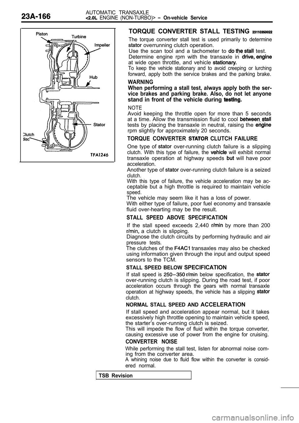
TORQUE CONVERTER STALL TESTING
The torque converter stall test is used primarily to determine
overrunning clutch operation.
Use the scan tool and a tachometer to
test.
Determine engine rpm with the transaxle in
at wide open throttle, and vehicle
To keep the vehicle stationary and to avoid creepin g or lurching
forward, apply both the service brakes and the parking brake.
WARNING
When performing a stall test, always apply both the ser-
vice brakes and parking brake. Also, do not let any one
stand in front of the vehicle during
NOTE
Avoid keeping the throttle open for more than 5 seconds
at a time. Allow the transmission fluid to cool
tests by placing the transaxle in neutral, raising the
rpm slightly for approximately 20 seconds.
TORQUE CONVERTER CLUTCH FAILURE
One type of over-running clutch failure is a slipping
clutch. With this type of failure, the will exhibit normal
transaxle operation at highway speeds will have poor
acceleration.
Another type of over-running clutch failure is a seized
clutch.
With this type of failure, the vehicle acceleration may be ac-
ceptable but a high throttle is required to maintai n vehicle
speed.
The vehicle may seem like it has a loss of power.
With either type of failure, poor fuel economy and transaxle
fluid over-hearting may be the result.
STALL SPEED ABOVE SPECIFICATION
If the stall speed exceeds 2,440 by more than 200
a clutch is slipping.
Diagnose the clutch circuits by performing hydrauli c and air
pressure tests.
The clutches of the transaxles may also be checked
using information given through the input and outpu t speed
sensors to the TCM.
STALL SPEED BELOW SPECIFICATION
If stall speed is below specification, the
over-running clutch is slipping. During the road te st, if poor
acceleration occurs through the gears with normal t ransaxle
operation at highway speeds, the vehicle has a slip ping
clutch.
NORMAL STALL SPEED AND ACCELERATION
If stall speed and acceleration appear normal, but it takes
excessively high throttle opening to maintain vehic le speed,
the starter’s over-running clutch is seized.
This will impede the flow of fluid within the torqu e converter,
causing excessive use of power from the engine for cruising.
CONVERTER NOISE
While performing the stall test, listen for abnormal noise com-
ing from the converter area.
A whining noise due to fluid flow within the conver ter is consid-
ered normal.
TSB Revision
Page 2098 of 2103
INTRODUCTION . . . . . . . . . . . . . . . .
6ALPHABETICAL INDEX
KEY INTERLOCK MECHANISM
Check ENGINE (NON-TURBO)> . . . . . . . . . . .
ENGINE (TURBO) AND ENGINE> .
ENTRY SYSTEM . . . . . . . . . . . . . . . . . . . .
SERVO
. . . . . . . . . . . . . . . . . . .
. . . . . . . . . . . . . . . . . . . .
Adjustment ENGINE (TURBO) AND ENGINE> . . . . . . . . . . . . . . . .
KNOCK SENSOR
ENGINE (NON-TURBO)> . . . . . . . . . . . . ENGINE (TURBO)> . . . . . . . . . . . . . . . . . . , .
KNUCKLE
. . . . . . . . . . . . . . . . . . . . . . . . . . . . . . .
. . . . . . . . . . . . . . . . . . . . . . . . . . . . . . .
. . . .
. . . . . . . . . . . . . . . . . . . . . . . . . . . .
LASH ADJUSTER
Check
. . . . . . . . . . . . . . . . . . . . . . . . . . . . .
. . . . . . . . . . . . . . . . . . . . . . . . . . . . . . .. . . . . . . . . . . . . . . . . . . . . . . . . . . . . . . . . . . .Replacement. . . . . . . . . . . . . . . . . . . . . . . . . .LATCH, Door. . . . . . . . . . . . . . . . . . . . . . . . . . . . . . . . . . . . . . . . .LATERAL LOWER ARM. . . . . . . . . . . . . . . . . . . . . . . . . . . . . .LEAK, Refrigerant, Repair. . . . . . . . . . . . . . . . . . . . . . . . . . . . . .LEVEL
Transfer Oil, Check ENGINE (TURBO) AND ENGINE>. . . . . . . . . . . . . . . . . . . . . . . . . . . . . . . . . . .Transaxle Fluid, Check ENGINE (NON-TURBO)> . . . . . . . . . . . . . .
ENGINE (TURBO) AND ENGINE>.. . . .LEVER Parking Brake
. . . . . . . . . . . . . . . . . . . . . . . . . . . . . . . . . . . . . . .Parking Brake, Stroke Check. . . . . . . . . . . . . . . . . . . . . . . . . .Selector, Operation Check ENGINE (NON-TURBO)>. . . . . . . . . . . . . . . . ENGINE (TURBO) AND ENGINE>.. . . .
. . . . . . . . . . . . . . . . . . . . . . . . . . . . . . . . . . . . . . . . . . . . GLASS. . . . . . . . . . . . . . . . . . . . . . . . . . . . . . . . . . . .LIGHT
Back-up. . . . . . . . . . . . . . . . . . . . . . . . . . . . . . . . . . . . . . . . . .Fog. . . . . . . . . . . . . . . . . . . . . . . . . . . . . . . . . . . . . . . . . . . . . .
Front Side-marker. . . . . . . . . . . . . . . . . . . . . . . . . . . . . . . . .Front Turn-signal. . . . . . . . . . . . . . . . . . . . . . . . . . . . . . . . . .High-mounted Stop. . . . . . . . . . . . . . . . . . . . . . . . . . . . . . . .Interior. . . . . . . . . . . . . . . . . . . . . . . . . . . . . . . . . . . . . . . . . . .Position. . . . . . . . . . . . . . . . . . . . . . . . . . . . . . . . . . . . . . . . . .Rear Combination. . . . . . . . . . . . . . . . . . . . . . . . . . . . . . . . .LIMITED SLIP DIFFERENTIAL (VCU TYPE) CONDITION,Check. . . . . . . . . . . . . . . . . . . . . . . . . . . . . . . . . . . . . . . . . . . .LINE PRESSURE, Adjustment ENGINE (TURBO)
AND ENGINE>. . . . . . . . . . . . . .. . . . . . . . . . . . . . . . . . .LINING
Brake, Thickness Check
. . . . . . . . . . . . . . . . . . . . . . . . . . .Drum Brake, Rear, Maintenance. . . . . . . . . . . . . . . . . . . . . .Running-in. . . . . . . . . . . . . . . . . . . . . . . . . . . . . . . . . . . . . . . . .LOWER ARM. . . . . . . . . . . . . . . . . . . . . . . . . . . . . . . . . . . . . . . . .LOW-REVERSE BRAKE
. . . . . . . . . . . . . . . . . . . . . . . . . . . . . . . .
. . . . . . . . . . . . . . . . . . . . . . . . . . . . . . . . . . . . . . . .LSD CASE . . . . . . . . . . . . . . . . . . . . . . . . . . . . . . . . . . . .LUMINOUS INTENSITY, Measurement. . . . . . . . . . . . . . . . . .
MAGNETIC CLUTCH, Test. . . . . . . . . . . . . . . . . . . . . . . . . . . . . .MAIN MUFFLER. . . . . . . . . . . . . . . . . . . . . . . . . . . . . . . . . . . . . .MAINTENANCE. . . . . . . . . . . . . . . . . . . . . . . . . . . . . . . . . . . . .MANIFOLD
ENGINE (NON-TURBO)>. . . . . . . . . . . . . .
. . . . . . . . . . . . . . . . . . . . . . . . . . . .11 ENGINE (TURBO)>. . . . . . . . . . . . . . . . . . .
. . . . . . . . . . . . . . . . . . . . . . . . . . . . . ENGINE>. . . . . . . . . . . . . . . . . . . . . . . . . . . .. . . . . . . . . . . . . . . . . . . . . . . . . . . . . . . . . . .Intake ENGINE (NON-TURBO)>. . . . . . . . . . . . . . . . .
. . . . . . . . . . . . . . . . . . . . . . . . . . . . . ENGINE (TURBO)>. . . . . . . . . . . . . . . . . . . . .
. . . . . . . . . . . . . . . . . . . . . . . . . . . . . . . ENGINE>. . . . . . . . . . . . . . . . . . . . . . . . . . . . . .
. . . . . . . . . . . . . . . . . . . . . . . . . . . . . . . . . . . .Intake, Vacuum Check. . . . . . . . . . . . . . . . . . . . . . . . . . . . . . .Vacuum Check . . . . . . . . . . . . . . . . . . . . .
. . . . . . . . . . . . . . . . . . . . . . .
. . . . . . . . . . . . . . . . . . . . . . . . . .MANUAL TRANSAXLE OIL, Maintenance. . . . . . . . . . . . . . . .MASTER CYLINDER
. . . . . . . . . . . . . . . . . . . . . . . . . . . . . . . . . . . . . . . . . .
. . . . . . . . . . . . . . . . . . . . . . . . . . . . . . . . . .METERS, Combination. . . . . . . . . . . . . . . . . . . . . . . . . . . . . . . .MIRRORDoor. . . . . . . . . . . . . . . . . . . . . . . . . . . . . . . . . . . . . . . . . .Rear View, Inside. . . . . . . . . . . . . . . . . . . . . . . . . . . . . . . . .MIXTURE
Idle, Check
. . . . . . . . . . . . . . . . . . . . . . . . . .
. . . . . . . . . . . . . . . . . . . . . . . . . .
. . . . . . . . . . . . . . . . . . . . . . . . . . . . . . . .MODULE, Fuel Pump ENGINE>. . . . . . . . . .MOLDINGS. . . . . . . . . . . . . . . . . . . . . . . . . . . . . . . . . . . . . . . . . . .MOTORIdle Air Control (DC Motor), On-vehicle Inspection ENGINE>. . . . . . . . . . . . . . . . . . . . . . . . . . . . . . . . .Idle Air Control (Stepper Motor ENGINE (NON-TUROn-vehicle Inspection. . . . . . . . . . . . . . . . ENGINE (TURBO)>. . . . . . . . . . . . . . . . . . . . .Starter ENGINE (NON-TURBO)>. . . . . . . . . . . . . . ENGINE (TURBO) AND ENGINE> . .MOUNTING
Engine. . . . . . . . . . . . . . . . . . . . . . . . . . . . . . . . . . . . . . . . . . . . .Transaxle. . . . . . . . . . . . . . . . . . . . . . . . . . . . . . . . . . . . . . . . . .MUFFLER, Main. . . . . . . . . . . . . . . . . . . . . . . . . . . . . . . . . . . . . . FUEL INJECTION (MFI) RELAY (ASD RELAY)
On-vehicle Inspection ENGINE (NON-TURBO)>. . . . . . . . . . . . . . . . ENGINE (TURBO) AND ENGINE>.. . .
0
OIL Engine, Inspection . . . . . . . . . . . . . . . . . . . . . . . . . . . . . . . . . . .
Engine, Replacement . . . . . . . . . . . . . . . , . . . . . . . . . . . . . . . Gear,. . . . . . . . . . . . . . . . . . . . . Manual. . . . . . . . . . . . . . . . . . . . . Rear Axle, Maintenance
Temperature Sensor Continuity, Check . . . . . . . .
Transaxle, Maintenance . . . . . . . . . . . . . . . . . . . . . . . . . . . .
Transaxle, Replacement ENGINE (NON-TURBO)> . . . . . . . . . . . . ENGINE (TURBO) AND ENGINE>Transfer, Maintenance. . . . . . . . . . . . . . . . . . . . .
.. . .. .