hood release MITSUBISHI SPYDER 1990 Service Repair Manual
[x] Cancel search | Manufacturer: MITSUBISHI, Model Year: 1990, Model line: SPYDER, Model: MITSUBISHI SPYDER 1990Pages: 2103, PDF Size: 68.98 MB
Page 25 of 2103
GENERAL Towing and Hoisting
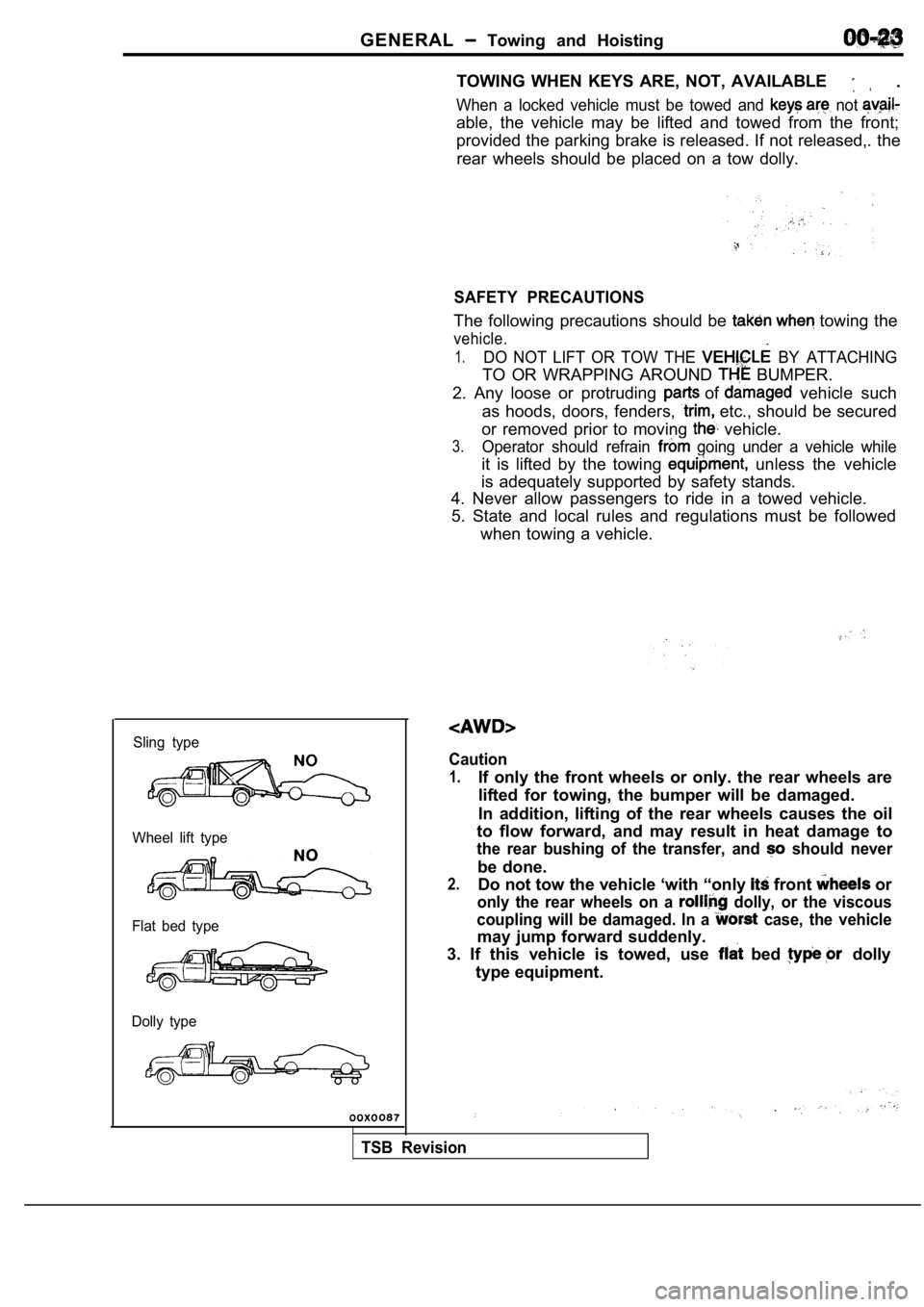
Sling type
Wheel lift type
Flat bed type
Dolly type
TOWING WHEN KEYS ARE, NOT, AVAILABLE .
When a locked vehicle must be towed and not
able, the vehicle may be lifted and towed from the front;
provided the parking brake is released. If not rele ased,. the
rear wheels should be placed on a tow dolly.
SAFETY PRECAUTIONS
The following precautions should be towing the
vehicle.
1.DO NOT LIFT OR TOW THE BY ATTACHING
TO OR WRAPPING AROUND BUMPER.
2. Any loose or protruding
of vehicle such
as hoods, doors, fenders,
etc., should be secured
or removed prior to moving
vehicle.
3.Operator should refrain going under a vehicle while
it is lifted by the towing unless the vehicle
is adequately supported by safety stands.
4. Never allow passengers to ride in a towed vehicl e.
5. State and local rules and regulations must be fo llowed
when towing a vehicle.
Caution
1.If only the front wheels or only. the rear wheels a re
lifted for towing, the bumper will be damaged.
In addition, lifting of the rear wheels causes the oil
to flow forward, and may result in heat damage to
the rear bushing of the transfer, and should never
be done.
2.Do not tow the vehicle ‘with “only front or
only the rear wheels on a dolly, or the viscous
coupling will be damaged. In a
case, the vehicle
may jump forward suddenly.
3. If this vehicle is towed, use
bed dolly
type equipment.
TSB Revision
Page 1106 of 2103
AUTOMATIC TRANSAXLE Automatic Transaxle Key Interlock
ENGINE (TURBO) AND ENGINE> and Shift Lock Mechanisms
23200120045
REMOVAL AND INSTALLATION
Caution:Be careful not to subject the SRS-ECU to any shocksduring removal and installation of the key interlockcable and shift lock cable.
567
I
- -
1 8 ’
NOTE(1) clip
(2) clipposition position
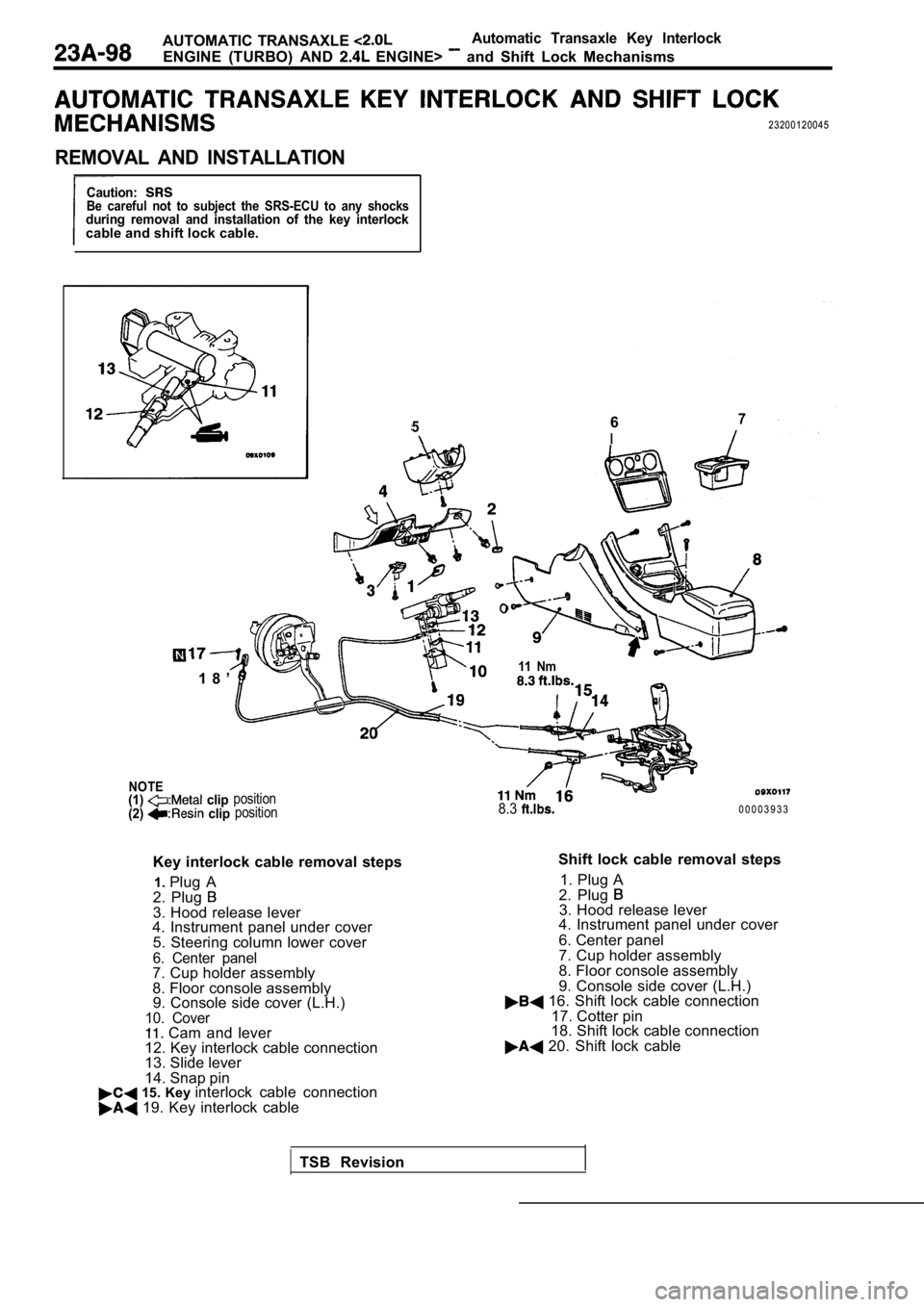
Key interlock cable removal steps
1. Plug A
2. Plug
3. Hood release lever
4. Instrument panel under cover
5. Steering column lower cover
6. Center panel7. Cup holder assembly
8. Floor console assembly9. Console side cover (L.H.)
10. Cover Cam and lever
12. Key interlock cable connection
13. Slide lever
14. Snap pin
15. Key interlock cable connection 19. Key interlock cable
11 Nm
8.30 0 0 0 3 9 3 3
Shift lock cable removal steps 1. Plug A
2. Plug
3. Hood release lever
4. Instrument panel under cover
6. Center panel
7. Cup holder assembly
8. Floor console assembly
9. Console side cover (L.H.)
16. Shift lock cable connection
17. Cotter pin
18. Shift lock cable connection
20. Shift lock cable
TSB Revision
Page 1198 of 2103

AUTOMATIC TRANSAXLE
E N G I N E ( N O N - T U R B O ) >Automatic
Transaxle KeyInterlock and Shift LockMechanisms
AUTOMATIC TRANSAXLE KEY INTERLOCK AND SHIFT LOCK
MECHANISMS
Caution: SRSBe careful not to subject the SRS-ECU to any shocksduring removal and installation of the key interloc kcable and shift lock cable.
NOTE
567I
8 ’
clipposition position
Key
interlock cable removal steps
1. Plug A
2. Plug
3. Hood release lever
4. Instrument panel under cover
5. Steering column lower cover
6. Center panel7. Cup holder assembly
8. Floor console assembly
9. Console side cover (L.H.)
10. Cover11. Cam and lever
12. Key interlock cable connection
13. Slide lever
14. Snap pin
15. Key interlock cable connection 19. Key interlock cable 11 Nm
8.3
Shift lock cable removal steps
1. Plug A
2. Plug
3. Hood release lever
4. Instrument panel under cover 6. Center panel
7. Cup holder assembly
8. Floor console assembly
9. Console side cover (L.H.)
16. Shift lock cable connection
17. Cotter pin
18. Shift lock cable connection
20. Shift lock cable
TSB Revision
Page 1825 of 2103
CONTENTS
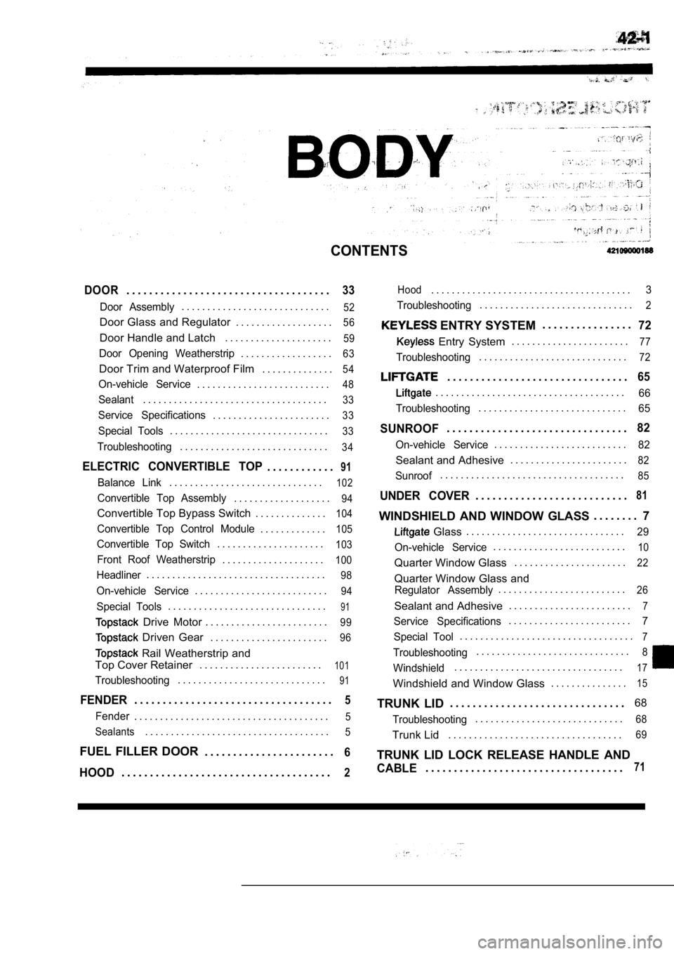
DOOR. . . . . . . . . . . . . . . . . . . . . . . . . . . . . . . . . . . .33
Door Assembly. . . . . . . . . . . . . . . . . . . . . . . . . . . . .52
Door Glass and Regulator . . . . . . . . . . . . . . . . . . .56
Door Handle and Latch. . . . . . . . . . . . . . . . . . . . .59
Door Opening Weatherstrip. . . . . . . . . . . . . . . . . .63
Door Trim and Waterproof Film . . . . . . . . . . . . . .54
On-vehicle Service. . . . . . . . . . . . . . . . . . . . . . . . . .48
Sealant. . . . . . . . . . . . . . . . . . . . . . . . . . . . . . . . . . . .33
Service Specifications. . . . . . . . . . . . . . . . . . . . . . .33
Special Tools. . . . . . . . . . . . . . . . . . . . . . . . . . . . . . .33
Troubleshooting. . . . . . . . . . . . . . . . . . . . . . . . . . . . .34
ELECTRIC CONVERTIBLE TOP. . . . . . . . . . . .91
Balance Link. . . . . . . . . . . . . . . . . . . . . . . . . . . . . .102
Convertible Top Assembly. . . . . . . . . . . . . . . . . . .94
Convertible Top Bypass Switch . . . . . . . . . . . . . .104
Convertible Top Control Module. . . . . . . . . . . . .105
Convertible Top Switch. . . . . . . . . . . . . . . . . . . . .103
Front Roof Weatherstrip. . . . . . . . . . . . . . . . . . . .100
Headliner. . . . . . . . . . . . . . . . . . . . . . . . . . . . . . . . . . .98
On-vehicle Service. . . . . . . . . . . . . . . . . . . . . . . . . .94
Special Tools. . . . . . . . . . . . . . . . . . . . . . . . . . . . . . .91
Drive Motor. . . . . . . . . . . . . . . . . . . . . . . .99
Driven Gear . . . . . . . . . . . . . . . . . . . . . . .96
Rail Weatherstrip and
Top Cover Retainer . . . . . . . . . . . . . . . . . . . . . . . .
101
Troubleshooting. . . . . . . . . . . . . . . . . . . . . . . . . . . . .91
FENDER. . . . . . . . . . . . . . . . . . . . . . . . . . . . . . . . . . .5
Fender. . . . . . . . . . . . . . . . . . . . . . . . . . . . . . . . . . . . . .5
Sealants
. . . . . . . . . . . . . . . . . . . . . . . . . . . . . . . . . . . .5
FUEL FILLER DOOR . . . . . . . . . . . . . . . . . . . . . . .6
HOOD. . . . . . . . . . . . . . . . . . . . . . . . . . . . . . . . . . . . .2
Hood. . . . . . . . . . . . . . . . . . . . . . . . . . . . . . . . . . . . . . .3
Troubleshooting
. . . . . . . . . . . . . . . . . . . . . . . . . . . . . .2
ENTRY SYSTEM . . . . . . . . . . . . . . . .72
Entry System
. . . . . . . . . . . . . . . . . . . . . . .77
Troubleshooting. . . . . . . . . . . . . . . . . . . . . . . . . . . . .72
. . . . . . . . . . . . . . . . . . . . . . . . . . . . . . . .65
. . . . . . . . . . . . . . . . . . . . . . . . . . . . . . . . . . . . .66
Troubleshooting
. . . . . . . . . . . . . . . . . . . . . . . . . . . . .65
SUNROOF. . . . . . . . . . . . . . . . . . . . . . . . . . . . . . . .82
On-vehicle Service. . . . . . . . . . . . . . . . . . . . . . . . . .82
Sealant and Adhesive . . . . . . . . . . . . . . . . . . . . . . .82
Sunroof. . . . . . . . . . . . . . . . . . . . . . . . . . . . . . . . . . . .85
UNDER COVER. . . . . . . . . . . . . . . . . . . . . . . . . . .81
WINDSHIELD AND WINDOW GLASS . . . . . . . .
7
Glass. . . . . . . . . . . . . . . . . . . . . . . . . . . . . . .29
On-vehicle Service
. . . . . . . . . . . . . . . . . . . . . . . . . .10
Quarter Window Glass . . . . . . . . . . . . . . . . . . . . . .22
Quarter Window Glass and
Regulator Assembly. . . . . . . . . . . . . . . . . . . . . . . . .26
Sealant and Adhesive. . . . . . . . . . . . . . . . . . . . . . . .7
Service Specifications. . . . . . . . . . . . . . . . . . . . . . . .7
Special Tool
. . . . . . . . . . . . . . . . . . . . . . . . . . . . . . . . . .7
Troubleshooting. . . . . . . . . . . . . . . . . . . . . . . . . . . . . .8
Windshield. . . . . . . . . . . . . . . . . . . . . . . . . . . . . . . . .17
Windshield and Window Glass . . . . . . . . . . . . . . .15
TRUNK LID. . . . . . . . . . . . . . . . . . . . . . . . . . . . . . . 68
Troubleshooting. . . . . . . . . . . . . . . . . . . . . . . . . . . . .68
Trunk Lid
. . . . . . . . . . . . . . . . . . . . . . . . . . . . . . . . . .69
TRUNK LID LOCK RELEASE HANDLE AND
CABLE. . . . . . . . . . . . . . . . . . . . . . . . . . . . . . . . . . .71
Page 1827 of 2103
REMOVAL AND INSTALLATION
0 0 0 0 3 7 9 7Adjustment of clearance around
hood and height
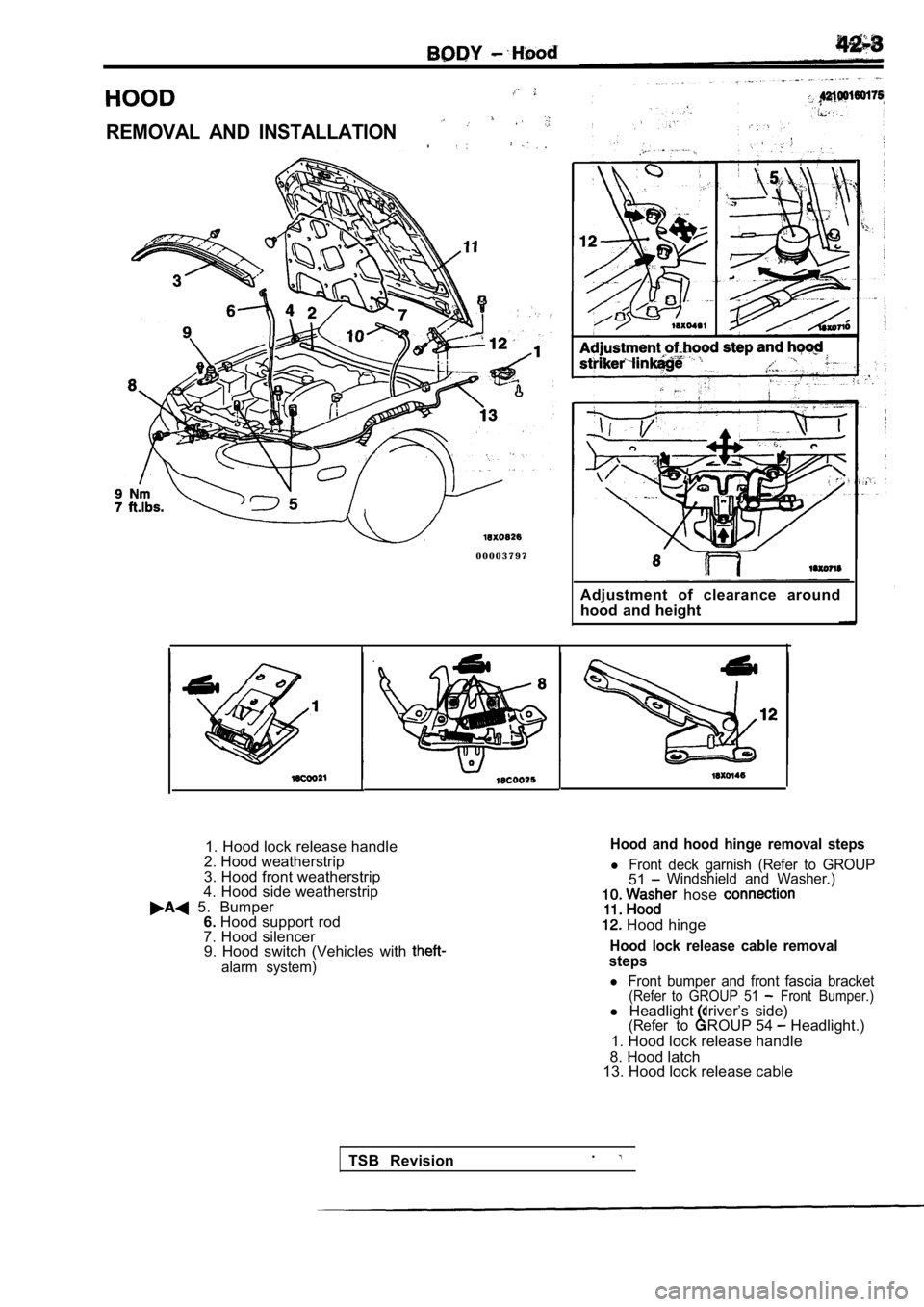
1. Hood lock release handle
2. Hood weatherstrip
3. Hood front weatherstrip
4. Hood side weatherstrip
5. Bumper 6. Hood support rod
7. Hood silencer 9. Hood switch (Vehicles with
alarm system)
Hood and hood hinge removal steps
l Front deck garnish (Refer to GROUP51Windshield and Washer.)
hose
Hood hinge
Hood lock release cable removal
steps
l Front bumper and front fascia bracket(Refer to GROUP 51 Front Bumper.)l Headlight driver’s side)(Refer toROUP 54 Headlight.)
1. Hood lock release handle
8. Hood latch
13. Hood lock release cable
TSB Revision .
Page 1961 of 2103
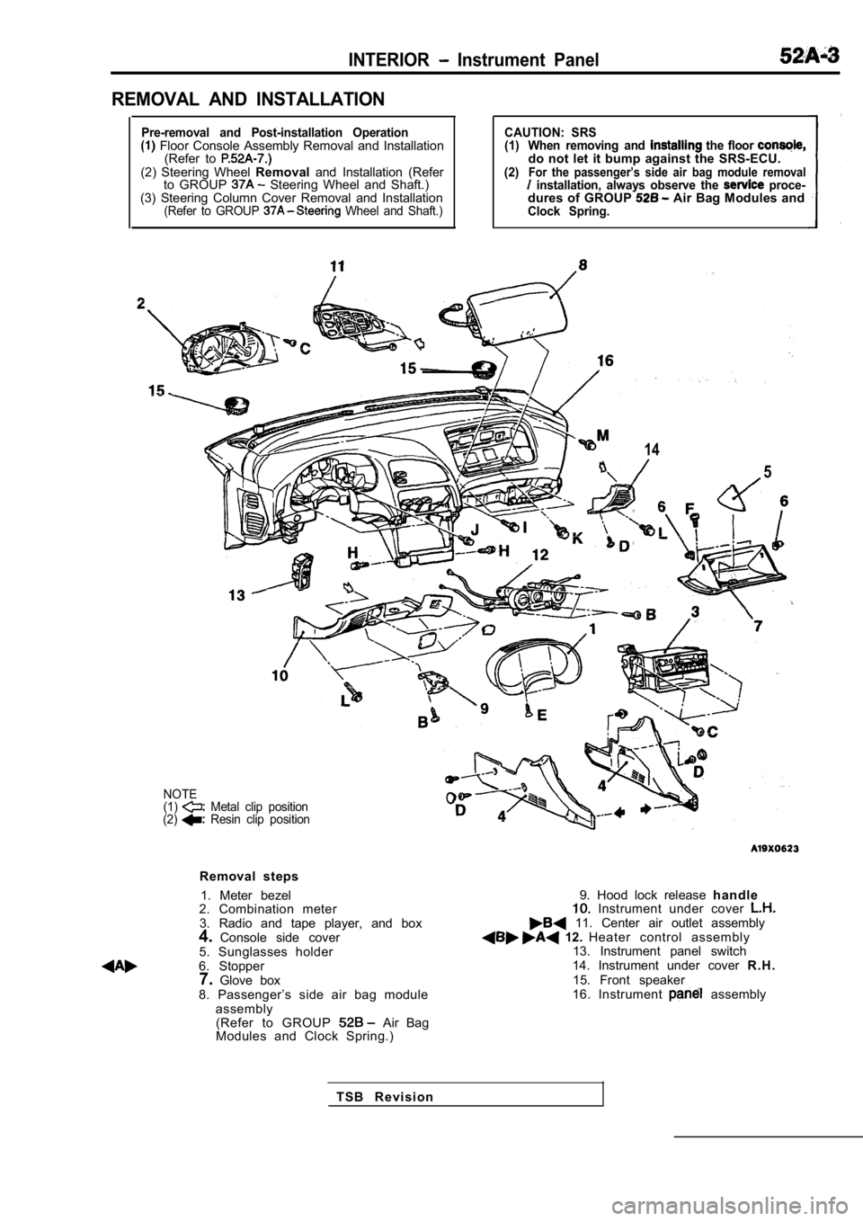
INTERIOR Instrument Panel
REMOVAL AND INSTALLATION
Pre-removal and Post-installation Operation Floor Console Assembly Removal and Installation(Refer to
(2) Steering Wheel Removaland Installation (Refer
to GROUP Steering Wheel and Shaft.)
(3) Steering Column Cover Removal and Installation
(Refer to GROUP Wheel and Shaft.)
CAUTION: SRS
(1) When removing and the floor do not let it bump against the SRS-ECU.(2)For the passenger’s side air bag module removal installation, always observe the proce-dures of GROUP Air Bag Modules andClock Spring.
14
5
NOTE
(1) Metal clip position
(2) Resin clip position
Removal steps
1. Meter bezel
2. Combination meter
3. Radio and tape player, and box
4. Console side cover
5. Sunglasses holder
6. Stopper 7. Glove box
8. Passenger’s side air bag module assembly(Refer to GROUP
Air Bag
Modules and Clock Spring.)
9. Hood lock release h a n d l e Instrument under cover 11. Center air outlet assembly 12. Heater control assembly
13. Instrument panel switch
14. Instrument under cover R . H .
15. Front speaker
16. Instrument
assembly
T S B R e v i s i o n
Page 2089 of 2103
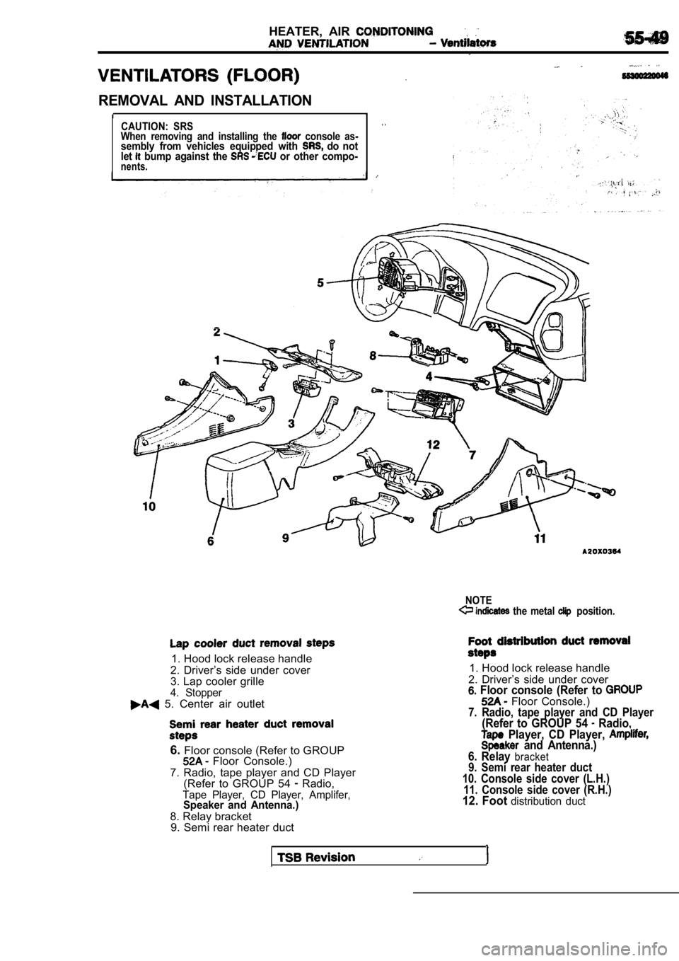
HEATER, AIR
REMOVAL AND INSTALLATION
I1
CAUTION: SRS
When removing and installing the console as-sembly from vehicles equipped with do not
let bump against the or other compo-nents.
. .
NOTE the metal position.
1. Hood lock release handle
2. Driver’s side under cover
3. Lap cooler grille
4. Stopper 5. Center air outlet
6. Floor console (Refer to GROUP Floor Console.)
7. Radio, tape player and CD Player (Refer to GROUP 54
Radio,Tape Player, CD Player, Amplifer,Speaker and Antenna.)
8. Relay bracket9. Semi rear heater duct
1. Hood lock release handle
2. Driver’s side under cover
Floor console (Refer to Floor Console.)7. Radio, tape player and CD Player(Refer to GROUP 54 Radio, Player, CD Player, and Antenna.)
6. Relay bracket9. Semi rear heater duct
10. Console side cover (L.H.) 11. Console side cover (R.H.)
12. Foot distribution duct