headlamp NISSAN 300ZX 1984 Z31 Electrical System Workshop Manual
[x] Cancel search | Manufacturer: NISSAN, Model Year: 1984, Model line: 300ZX, Model: NISSAN 300ZX 1984 Z31Pages: 116, PDF Size: 3.42 MB
Page 1 of 116
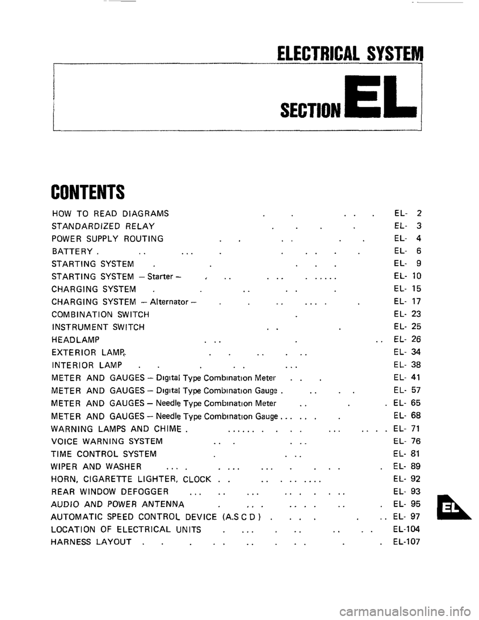
ELECTRICAL SYSTEM
I
SECTION EL
CONTENTS
HOW TO READ DIAGRAMS
STANDARDIZED RELAY
POWER SUPPLY ROUTING
BATTERY.
.. ..
STARTING SYSTEM .
STARTING SYSTEM -Starter -
CHARGING SYSTEM .
CHARGING SYSTEM - Alternator
COMB IN AT1 ON SWITCH
INSTRUMENT SWITCH
HEADLAMP
EXTERIOR LAMP,
INTERIOR LAMP
.
..
..
..
..
..
... ......
..
.. ....
..
.. ...
EL- 2
EL- 3
EL- 4
EL- 6
EL- 9
EL-
10
EL- 15
EL- 17
EL- 23
EL- 25
EL- 26
EL- 34
EL- 38
METER AND GAUGES - Digital Type Combination Meter . . EL- 41
METER AND GAUGES - Digital Type Combination Gauge . .. .. EL- 57
METER AND GAUGES - Needle Type Combination Meter .. . EL- 65
METER AND GAUGES
- Needle Type Combination Gauge.. .... EL- 68
WARNING LAMPS AND CHIME. .......... ... .... EL- 71
VOICE WARNING SYSTEM
... ... EL- 76
TIME CONTROL SYSTEM ... EL- 81
WIPER AND WASHER .... .... ... ... . EL- 89
HORN, CIGARETTE LIGHTER, CLOCK . . ......... EL- 92
REAR WINDOW DEFOGGER
... .. ... ....... EL- 93
AUDIO AND POWER ANTENNA
,. . .... .. . EL- 95
AUTOMATIC SPEED CONTROL DEVICE (AS
C D ) . ... , . EL- 97
LOCATION OF ELECTRICAL UNITS
... .. .. .. EL-104
HARNESS LAYOUT
. . .. .. .. . EL-107
Page 26 of 116
HEADLAMP
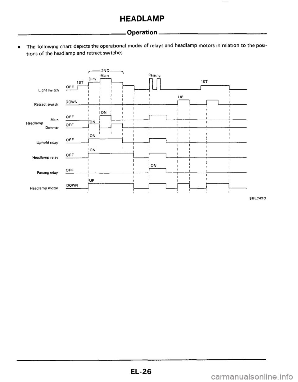
Operation
0 The following chart depicts the operational modes of relays and headlamp motors in relation to the posi-
nons
of the headlamD and retract switches
Light switch
Retract switch
Mal”
Dimmer Headlamp
Uphold relay
Headlamp relay
Pasrlng relay
Headlamp mofor
Parsing -2ND 7 Main
nn
1 ST
I I I
I I I I I , I , , 1 I 1 I , I I OFF 1 1 I I I I 1 I I OFF I I 1 I I I I I I II I I
UP
II 111
I
Ill I I I !
I j ON
I I
I ON
I I I I
I
OFF I
I I
I I I 1 I I1 1 I 1
I/ OFF
I I 1, I !I I OFF ~
I I UP DOWN
SEL743D
EL-26
Page 27 of 116

-
BATTERY TI RFI AV 1 7
THEFT WARNING
r --, I II
I
"$ 7; '/' '
PASSING RELAY
k=a-J \-UPHOLD RELAY
I
1V.
@ Wnihoul headlamp warning
0 Wnh headlamp warning
Page 28 of 116
HEADLAMP
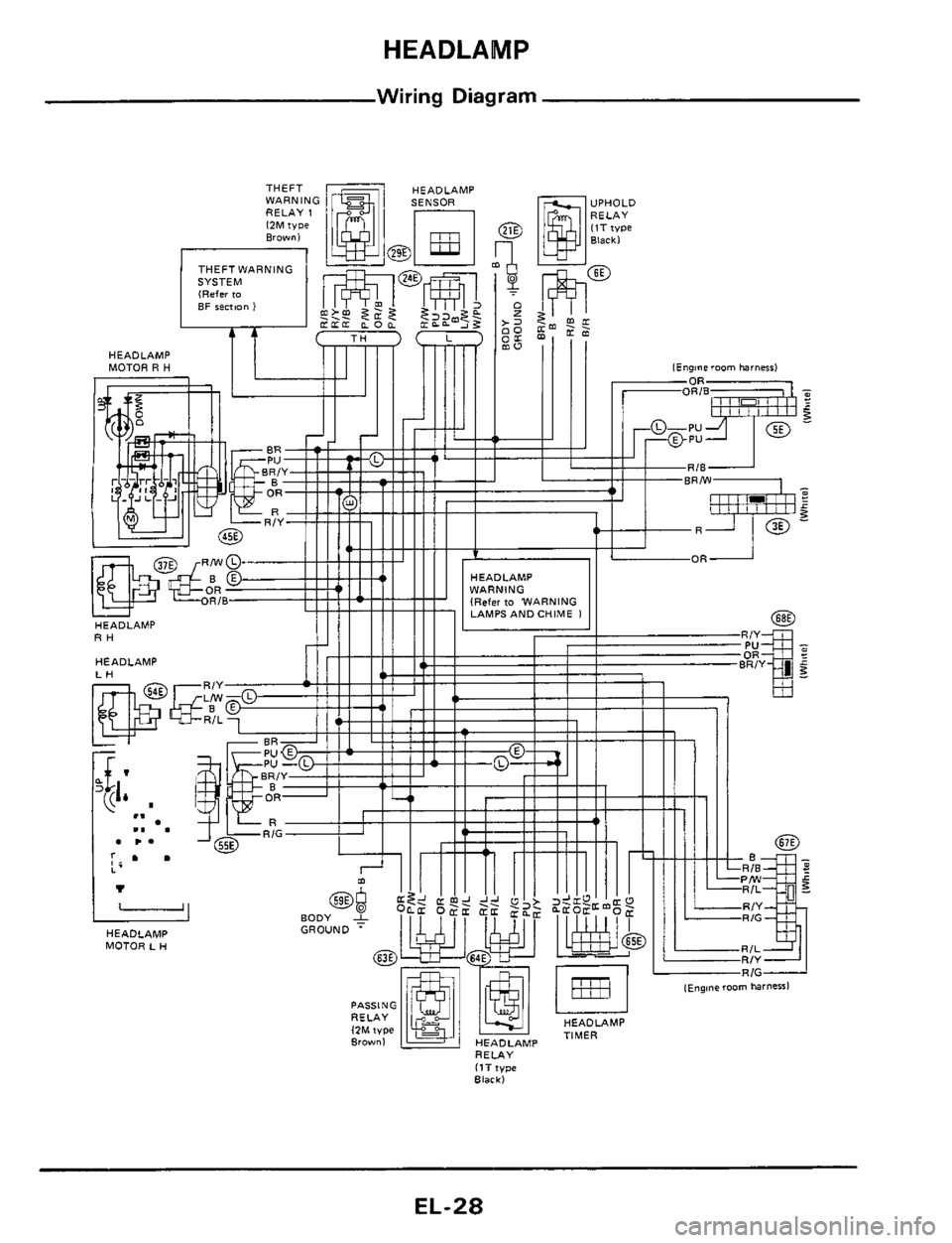
Wiring Diagram
HEADLAMP
MOTOR R H
RH
HEADLAMP
HEADLAMP
MOTOR L H
HEADLAMP
RELAY
ItT type Black)
EL-28
Page 30 of 116
HEADLAMP
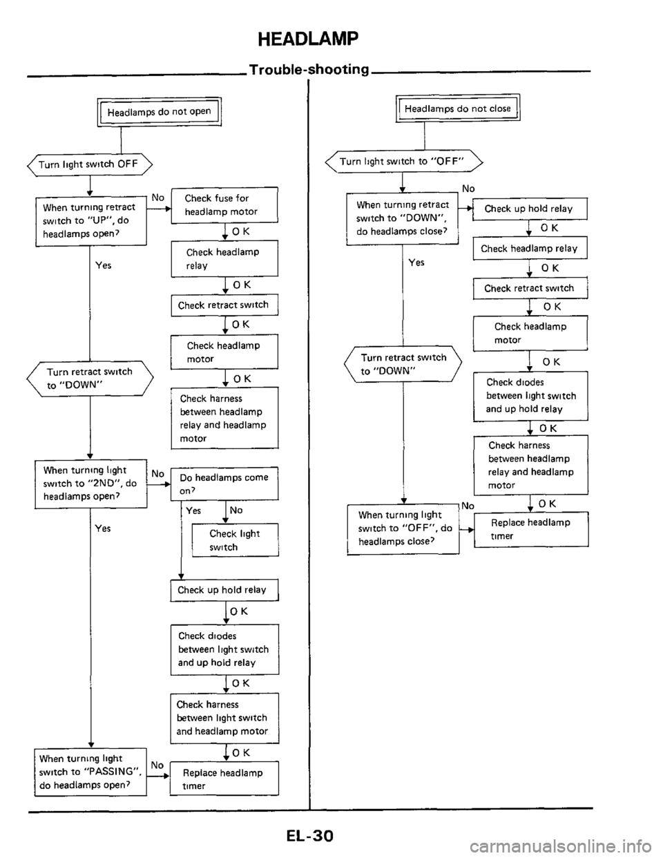
Trouble-shooting
Check diodes
between light switch
and up hold relay
1 OK
Check harness
between headlamp
relay and headlamp
motor
headlamp motor When turning retract
switch to
"UP", do
headlamps open?
Check headlamp
Yes relay
Check headlamp
motor
Turn retract switch
to "DOWN"
between headlamp
relay and headlamp
motor
v
When turning light
r switch to "ZND", do
-No When turning light
switch to "OFF". do
headlamps close? ~
on, I headlampsopen? I I
Replace
headlamp
timer -.
-
I
(es
switch
Check up hold relay 1 I
lo
Check diodes
between light switch
and up hold relay
OK
between light switch
and headlamp motor
When turning light
switch to "PASSING", Replace headlamp
do headlamps open?
Headlamps do not close
F
(Turn light switch to "OFF"
c - No
When turning retract
switch to "DOWN",
do headlamps close?
I - Check headlamp relay
Yes
Check retract switch
Check headlamp
EL-30
Page 32 of 116
HEADLAMP
Installation
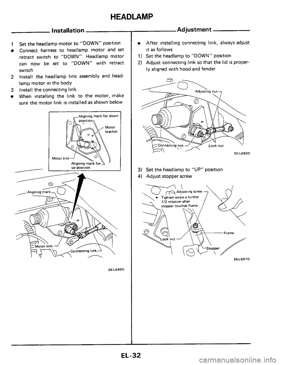
1 Set the headlamp motor to "DOWN" position
Connect harness
to headlamp motor and set
retract switch to "DOWN" Headlamp motor
can now be
set to "DOWN" with retract
switch Install the headlamp link assembly and head-
lamp motor in the body
When installing the link to the motor, make
sure the motor link is installed as shown below
2
3 Install the connecting link
,Aligning mark fordown
Motor
SEL649D
Adjustment
After installing connecting link, always adjust
it as follows
1) Set the headlamp to "DOWN" positlon
2) Adjust connecting link so that the lid IS proper-
ly aligned with hood and fender
3) Set the headlamp to "UP" position
4) Adjust stopper screw
SEL65'D
EL-32
Page 33 of 116
HEADLAMP
0
0
Headlamp Motor Check
0 No
8 Yes
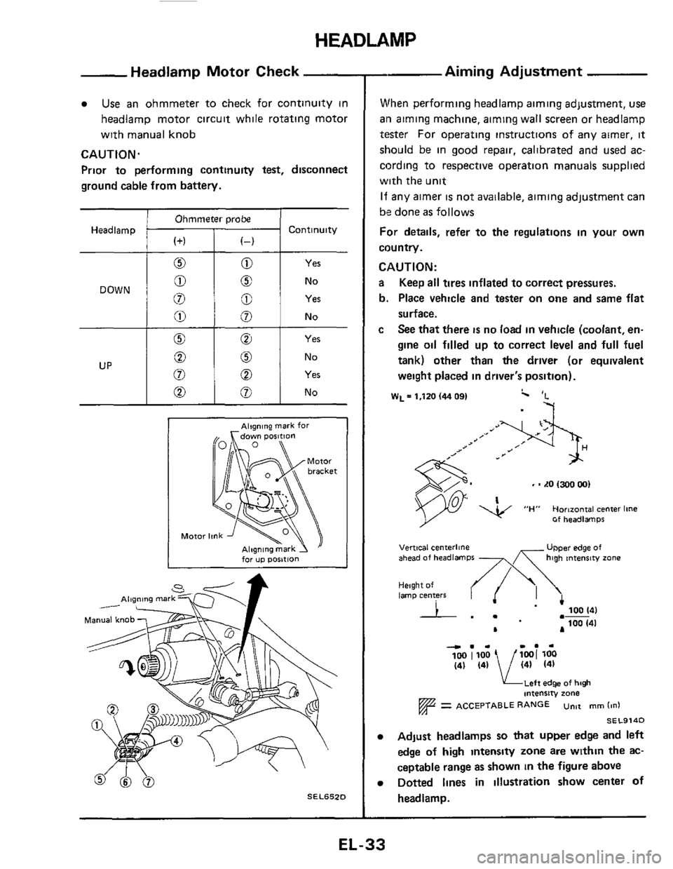
Use an ohmmeter to check for continuity in
headlamp motor circuit while rotating motor
with manual knob
CAUTION.
Prior to performing continuity test, disconnect
ground cable from battery.
Ohmmeter probe
Headlamp Continuity
Yes
No
Alqning mark for
for up posltlon
SEL652D
- Aiming Adjustment
When performing headlamp aiming adjustment, use
ail aiming machine, aiming wall screen or headlamp
tester For operating instructions of any airner, it
should be in good repair, calibrated and used ac-
cording to respective operation manuals supplied
with the unit
If any aimer is not available, aiming adjustment can
be done
as follows
For details, refer to the regulations in your own
country.
CAUTION:
a Keep all tires inflated to correct pressures.
b. Place vehicle and tester on
one and same flat
surface.
c See that there is no load in vehicle (coolant, en-
gine oil filled up to correct level and full fuel
tank) other than
the driver (or equivalent
weight placed in driver's position).
W~=l,ltO(4409I c 'L
-7
, - LO 1300 001
Of headlamps
UPper edge of Vertical centerline ahead of headlamps -x high tntenrw zone
Height of lamp centers I .- 100 141
100 (41 .-
L A
4.. I.. 100 1100 1001 loo (41 (41 / (41 (41
KLeft edge of high intensity zone
= ACCEPTABLE RANGE untt mm (in1
SEL914D
Adjust headlamps so that upper edge and left
edge
of high intensty zone are within the ac-
ceptable range as shown
in the figure above
Dotted lines in illustration show center of
headlamp.
EL-33
Page 37 of 116
EXTERIOR LAMP
-
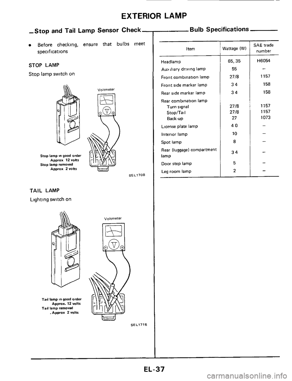
Item
-
Headlamp
Au, iliary driving lamp
Front combination lamp
Front side marker lamp
Rear side marker lamp
Rear cornbination lamp
1-urn signal
StopITail
Elack-up
Lictme plate lamp
Interior lamp
Spot lamp
Rear (luggage) compartment
lamp
Door step lamp
Leg room lamp
-
-Stop and Tail Lamp Sensor Check,
0 Before checking, ensure that bulbs meet Wattage (W)
65,35
55
2718 34
34
2718
2718
27
40
10
a
34
5
2
soecif ications
STOP LAMP
Stop lamp switch on
Stop lamp on good order
stop lamp removed Approx 12 volts
Approx 2volt6
voltmeter
SEL170B
TAIL LAMP
Lighting switch on
Tad lamp mgood order
Tail lamp removed ~pprox. 12 vans
. Approx 2 volts
SEL1710
- Bulb Specifications
SAE trade
number
Hi3054
-
1157
158 158
1157 1157
1073
-
-
-
-
-
-
EL-37
Page 75 of 116
WARNING LAMPS AND CHIME
Diode Check
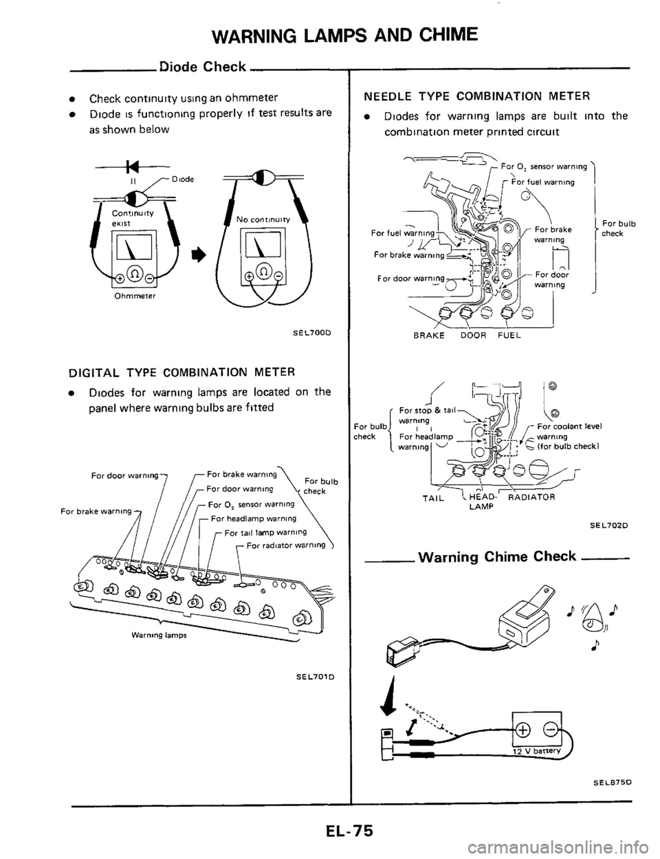
Check continuity using an ohmmeter
Diode
is functioning properly if test results are
as shown below
--I+-- 11 ,- Diode
Ohmmeter
NO continuity
@
SEL700D
DIGITAL TYPE COMBINATION METER
Diodes for warning lamps are located on the
panel where warning bulbsare fitted
For bulb check
For brake warning
7f For door warning
Far door warning
For tail lamp warning
For radmtor warning
Far 0, sensor warning
Far headlamp warning For brake warning
SEL701D
-~
NEEDLE TYPE COMBINATION METER
Diodes for warning lamps are built into the
Combination meter printed circuit
7- For 0, sensor warning
BRAKE DOOR FUEL
For bulb check
LAMP
SEL70ZD
--Warning Chime Check
A
SEL875D
EL-75
Page 91 of 116
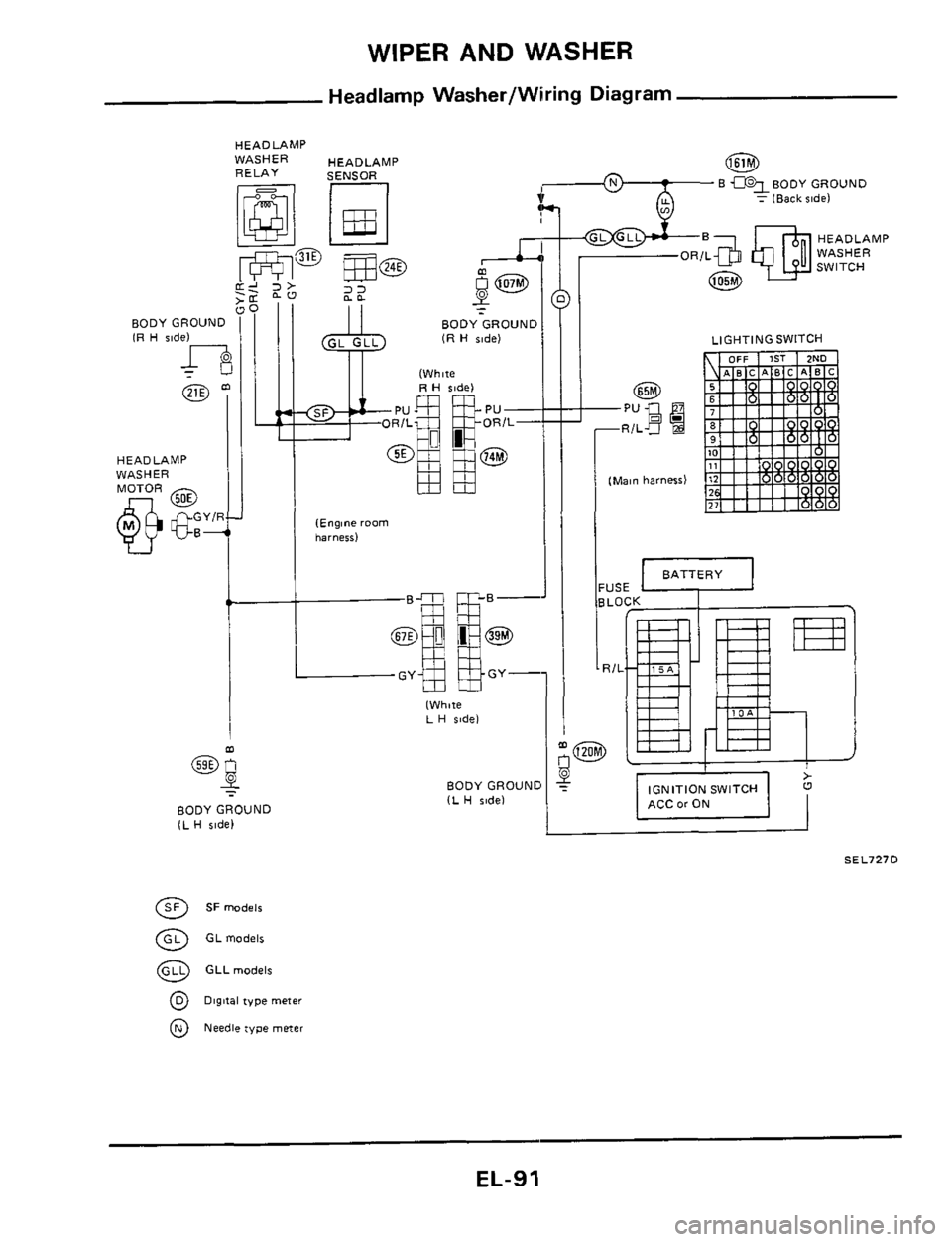
WIPER AND WASHER
Headlamp Washer/Wiring Diagram
HEADLAMP
RELAY
WASHER HEADLAMP @
: (Back ride)
HEADLAMP
WASHER
SWITCH
7
- 22 I1 BODY GROUND IR H ride)
HEADLAMP
WASHER
BODYGROUND (L H $#de)
@ GLmodelr
@ GLLrnodelr
@ Digital type meter
@ Needle type meiei
BODY GROl (R H ride)
II fWhw
(Engine room harnerr)
I LIGHTING SWITCH
J
(Main harness)
USE
7/1
w
II
IGNITION SWITCH I ACC or ON
I I
SEL727D
EL-91