NISSAN 300ZX 1984 Z31 Engine Fuel And Emission Control System Owner's Manual
Manufacturer: NISSAN, Model Year: 1984, Model line: 300ZX, Model: NISSAN 300ZX 1984 Z31Pages: 79, PDF Size: 2.15 MB
Page 21 of 79
E. C. C. S. DESCRIPTION
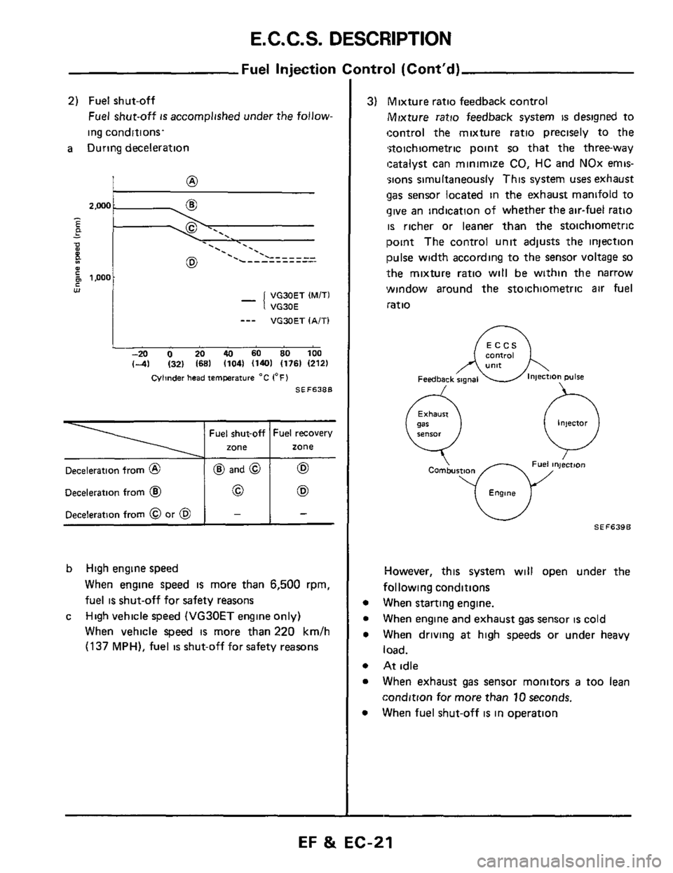
Deceleration from @
Deceleration from @
Deceleration from 0 or @
Fuel Injection
2) Fuel shut-off
Fuel shut-off is accomplished under the follow-
ing conditions.
a During deceleration
@ and @ 62
0 (E9
- -
- -.. . . . ._ '. .
VG30ET (MITI
VG30E
_-- VGXIET IA/Tl
-20 0 20 40 60 SO 100
(-41 1321 (681 11041 (1401 (1761 12121
Cvlinder head IemPerature "C 1°F)
SEF638B
b High engine speed
When engine speed is more than 6,500 rpm,
fuel
is shut-off for safety reasons
High vehicle speed
(VG30ET engine only)
When vehicle speed
is more than 220 km/h
(137 MPH), fuel is shut-off for safety reasons
c
mtrol (Cont'd)
3) Mixture ratio feedback control
Mixture ratio feedback system is designed to
control the mixture ratio precisely to the
*stoichiometric point
so that the three-way
!catalyst can minimize
CO, HC and NOx emis-
';ions simultaneously This system
uses exhaust
gas senwr located in the exhaust manifold to
give an indication of whether the air-fuel ratio
is richer or leaner than the stoichiometric
point The control unit adjusts the injection
pulse width according to the sensor voltage so
the mixture ratio will be within the narrow
window around the stoichiometric
air fuel
ratio
eontroi
Injector
0
Combustm
Engme
However, this system will open under the
following conditions
When starting engine.
When engine and exhaust
gas sensor is cold
When driving
at high speeds or under heavy
load.
At idle
When exhaust
gas sensor monitors a too lean
condition for more than
10 seconds.
When fuel shut-off
is in omration
EF & EC-21
Page 22 of 79
E.C.C.S. DESCRIPTION
-Fuel injection Control (Cont'd)-
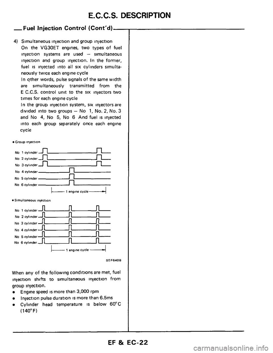
4) Simultaneous injection and group injection
On the VG30ET engines, two types of fuel
injection systems
are used - simultaneous
injection and group injection. In the former,
fuel is injected into all six cylinders simulta-
neously twice each engine cycle
In other words, pulse signals
of the same width
are simultaneously transmitted from the
E C.C.S. control unit to the six injectors two
times for each engine cycle
In the group injection system, six injectors are
divided into
two groups - No 1, No. 2, No. 3
and No 4, No 5, No 6 And fuel is injected
into each group separately once each engine
cycle
Group injection
NO 1 cylmder u
No 5 cylinder n
No 6cylinder _n
No 1 cylinder u
NO 2 cylinder -
u
u
u
u
NO 2 cylinder-
No 3 cylinder -
No 4 cylmdern
L- 1 engine cvcle4
. Slrnultaneous ln,ect,On
No 3 cylinder
No 4 cylinder
No 5 cylinder
No 6 cylinder
I 1 engm cycle I
SEF640B
When any of the following conditions are met, fuel
injection shifts to simultaneous injection from
group injection.
Engine speed is more than 3,000 rpm
Injection pulse duration is more than 6.5ms
Cylinder head temperature IS below 60°C
(1 40" F)
EF & EC-22
Page 23 of 79
E. C. C. S. DESCRIPTION
Ignition Timing Control
Engine speed and piston position Crank angle sensor
Amount of intake air Air flow meter
Temperature of engine Cylinder head temperature sensor
Throttle valve idle position
Vehicle speed Vehicle speed sensor (VG30ETl 1 I I
Start signal Ignition switch
Engine knocking Detonation sensor
Battery voltage Battery ~
Ignition
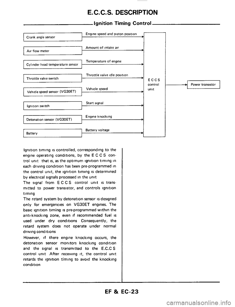
timing is controlled, corresponding to the
engine operating conditions, by the
E C C S con-
trol unit that
is, as the optimum ignition timing in
each driving condition has been pre-programmed in
the control unit, the ignition timing
IS determined
by electrical signals processed in the unit
The signal from
E C C S control unit is trans-
mitted to power transistor, and controls ignition
timing
The retard system by detonation sensor
is designed
only for emergencies on VG30ET engines. The
basic ignition timing
is pre-programmed within the
anti-knocking zone, even
if recommended fuel is
used under dry conditions Consequently, the
retard system does not operate under normal
driving conditions
However,
if there engine knocking occurs, the
detonation sensor monitors knocking condition
and the signal is transmitted to the E.C.C S
control unit After receiving it, the control unit
retards the ignition timing to avoid the knocking
condition
Power transistor
EF & EC-23
Page 24 of 79
E.C.C.S. DESCRIPTION
Battery voltage Battery
~-
Headlarnp switch Load signal
Cooling fan switch
Power steering oil pressure switch
Idle-up Control (VG30E engine)
Start signal Ignition switch
ECCS
control
unit
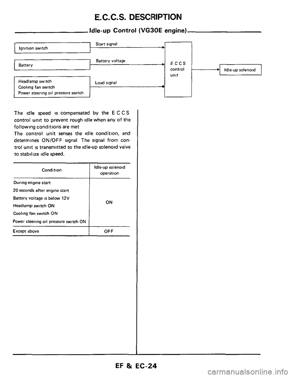
The idle speed is compensated by the E C C S
control unit to prevent rough idle when any of the
following conditions
are met
The control unit senses the idle condition, and
determines
ON/OFF signal The signal from con-
trol unit
is transmitted to the idle-uD solenoid valve
to stabilize idle speed.
Condition
During engine start
20 seconds after engine start
Battery voltage is below 12V
Headlarnp switch ON
Cooling fan switch ON
Power steering oil pressure switch ON
Except above
Idle-up solenoid
operation
ON
OFF
EF 8t EC-24
Page 25 of 79
E. C. C. S. DESCRIPTION
Start signal ’ Ignition switch
Throttle valve idle position
Neutral position t
Battery voltage Battery
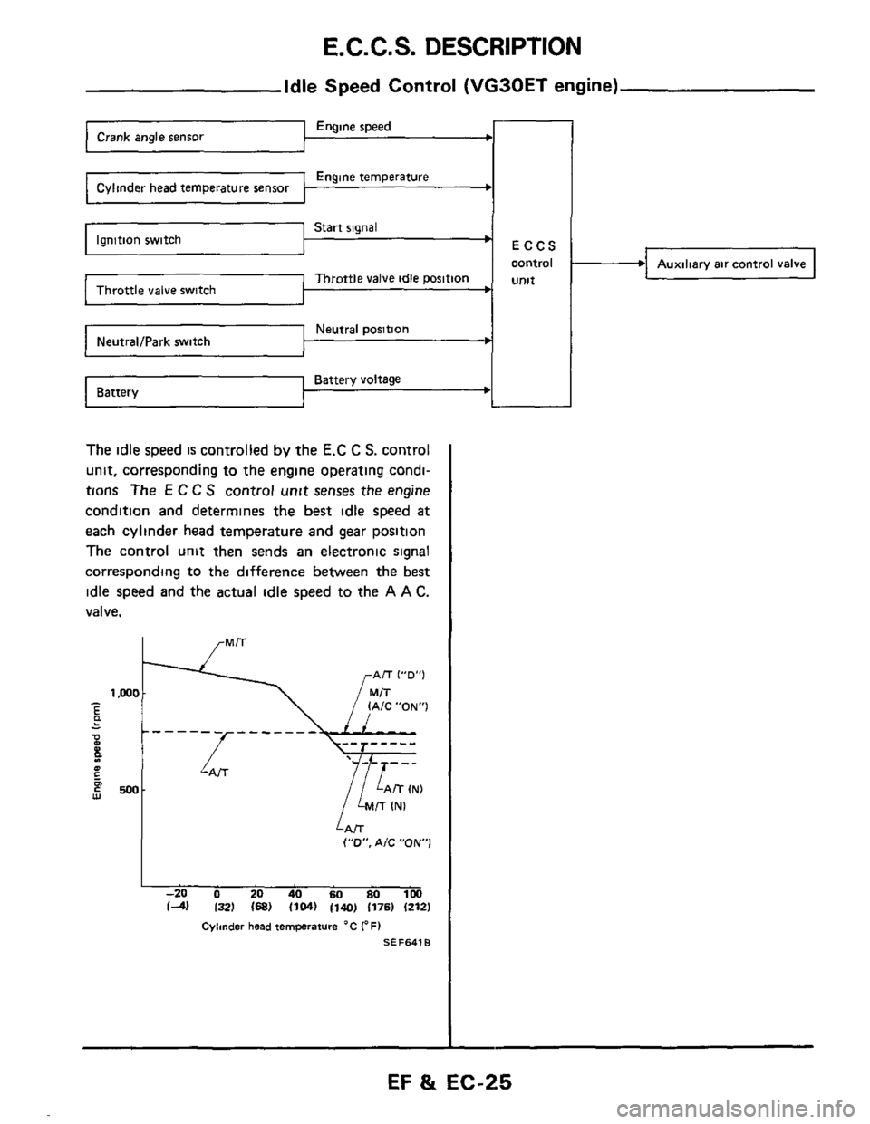
Idle Speed Control (VG30ET engine)
Engine speed
Engine temperature
ECCS
control
Unlt
-
The idle speed is controlled by the E.C C S. control
unit, corresponding to the engine operating condi-
tions
The E C C S control unit senses the engine
condition and determines the best idle speed
at
each cylinder head temperature and gear position
The control unit then sends an electronic signal
corresponding
to the difference between the best
idle speed and the actual idle speed to the A A C.
valve.
I
,/ lAiC”ON”1 -‘I E .. -
P - 0 E 4 1 - - - -L- - - - - - lZN)
500 w
LAiT (”0”. A/C ”ON1
I -20 0 20 40 60 80 1M) 14) I321 168) 11041 1140) 1176) (212)
Cylinder head ternprature “C (OF1
SEF641B
Auxiliary air control valve
EF & EC-25
Page 26 of 79
E.C.C.S. DESCRIPTION
Engine speed Crank angle sensor c
Engine temperature ’
Throttle valve idle position Throttle valve switch
Start signal
Exhaust Gas Recirculation (E.G. R.) Control
ECCS
control
unit
EGR
E G R control sclenoid valv
Throttle valve witch
C lhnder head era1“re semor
Crank angle sensor
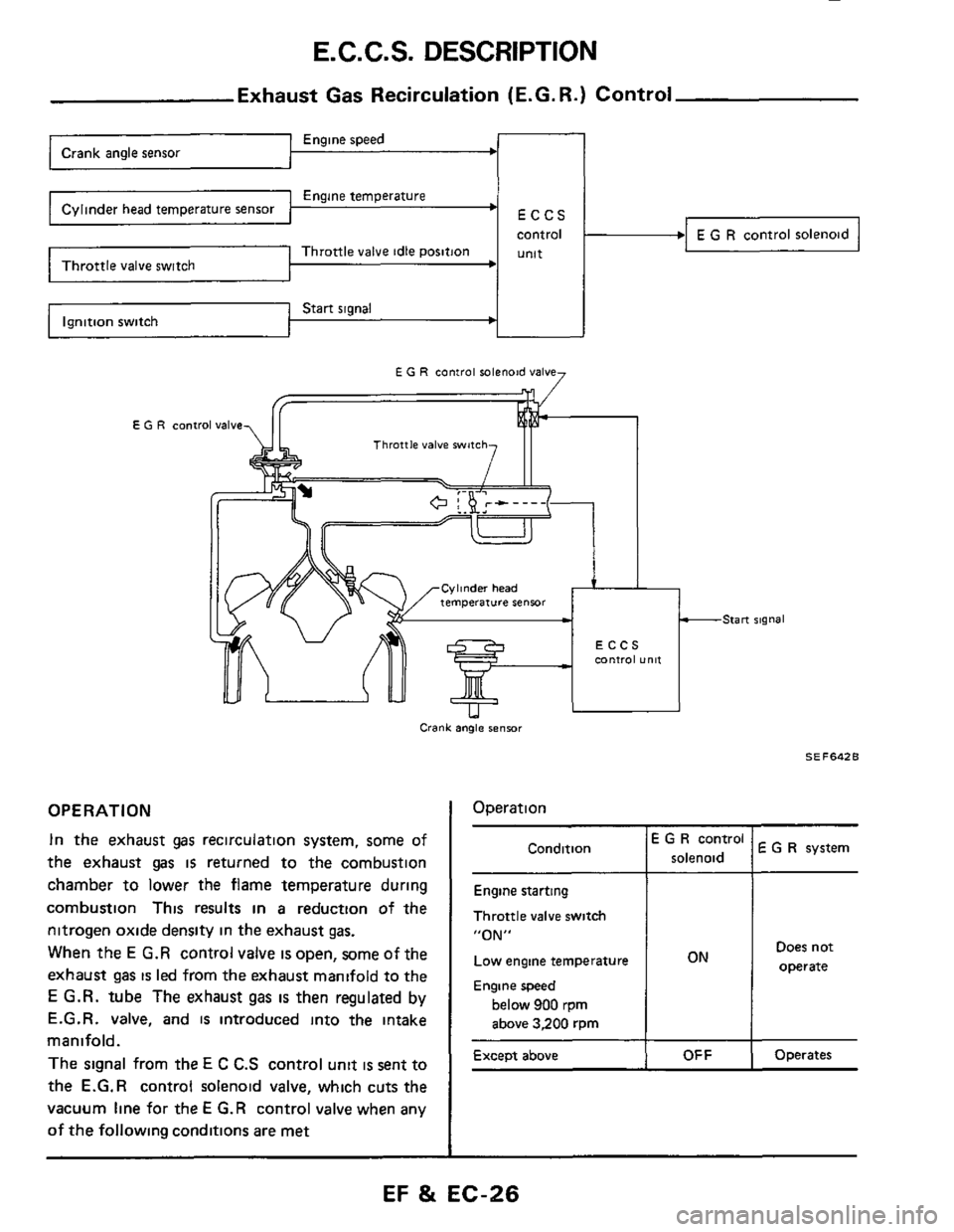
OPERATION
In the exhaust gas recirculation system, some of
the exhaust
gas is returned to the combustion
chamber to lower
the flame temperature during
combustion This results
in a reduction of the
nitrogen oxide density in the exhaust
gas.
When the E G.R control valve is open, some of the
exhaust
gas is led from the exhaust manifold to the
E G.R. tube The exhaust gas is then regulated by
E.G.R. valve, and
is introduced into the intake
manifold.
The signal from the E C C.S control unit is sent to
the
E.G.R control solenoid valve, which cuts the
vacuum line for the E G.R control valve when any
of the following conditions are met
-Start signal
SE F642 B
I Operation
E G R system I
Condition E G R control
solenoid
Engine starting
Throttle valve switch
“ON”
Low engine temperature Does not
Engine speed
below 900 rpm
above 3,200 rpm
Operates Except above
EF & EC-26
Page 27 of 79
E.C.C.S. DESCRIPTION
FUELPUMP ~
FUEL PUMP RELAY
Fuel Pump Control
108
ECCS
CONTROL UNIT
Engine speed --r
Engine temperature
control Fuel pump Start signal
Ignition
switch
position Engine
condition
Throttle valve idle position
Fuel pump Fuel pump
relay operation
Battery voltage Battery
Starting ON
ON for 30 Operates
seconds
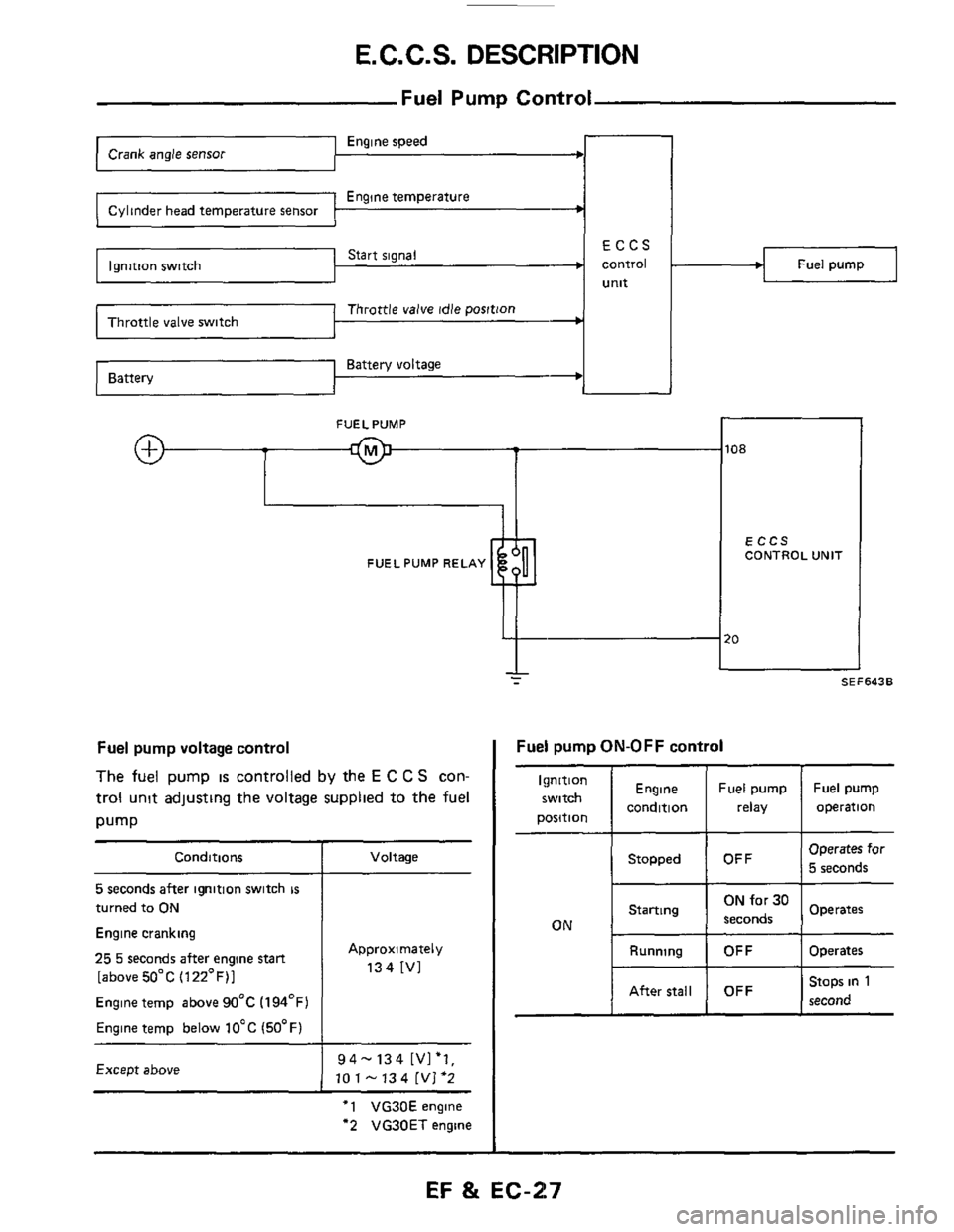
Fuel pump voltage control
The fuel pump is controlled by the E C C S con-
trol unit adjusting the voltage supplied to the fuel
pump
Conditions
5 seconds after ignition switch is
turned to ON
Engine cranking
25 5 seconds after engine stan
[above 50°C (122°F)1
Engine temp above 90°C (194OF)
Engine temp below 10°C (50°F)
Except above
Voltage
Approximately
134 [VI
94-134 [Vl'l,
10 1 - 13 4 [VI '2
'1 VG30E engine
"2 VG30ET engine
I SEF643B
Operates for
I OFF I 5 seconds Stopped
I Running I OFF I Operates
Stops in 1
I I I second After stall OFF
EF %t EC-217
Page 28 of 79
DIAGNOSTIC PROCEDURE
Caution
a. Before connecting or disconnecting E C C S
b
C
d
e
harness connector to or from any E C.C S.
unit, be sure to turn the ignition switch to the
"OFF" position and disconnect the negative
battery terminal
Otherwise, there may
be damage to control
unit
Do not attempt to disassemble any E C C S
component parts. To conduct electrical checks
on these component parts, closely follow the
steps outlined under "ELECTRONIC CON-
TROL SYSTEM INSPECTI0N"on pages EF
&
EC-43 through EF & EC-59.
When conducting self-diagnosing, follow the
steps outlined under "SELF-DIAGNOSIS" on
pages EF
& EC-35 through EF & EC-42 in
order to obtain accurate diagnosing results
After selfdiagnosing has been completed, erase
the memory properly
Always turn the diagnosis mode selector care-
fully using
a screwdriver If it is turned forci-
bly,
it may be damaged, resulting in the inabili-
ty to perform the self-diagnosing or to monitor
the mixture ratio
Before troubleshooting, ensure that
all harness
connectors are secure.
EF & EC-28
Page 29 of 79
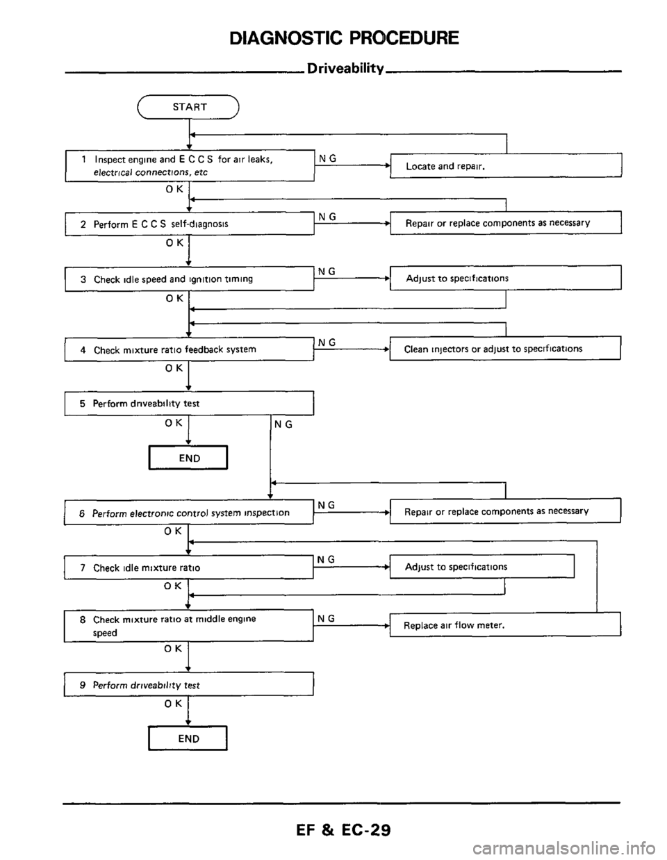
DIAGNOSTIC PROCEDURE
b NG 3 Check idle speed and ignition timing
Driveability
(--- START -l
Adjust to specifications
4 Check mixture ratio feedback system Clean injectors or adjust to specifications
I 5 Perform driveability test I
OK NG
Repair or replace components as necessary
P
6 Perform electronic control system inspection
OK I
Adjust to specifications
OK 1 I
NG 4-
7 Check idle mixture ratio
, I
I
Replace air flow meter. 8 Check mixture ratio at middle engine NG
speed
OK
) 9 Perform driveability test
EF & EC-29
Page 30 of 79

DIAGNOSTIC PROCEDURE
Driveabil
1. Inspect engine and E C C.S. for air leaks,
proper electrical connections, etc
1) Check all hoses and ducts for air leaks
2) Check air cleaner for clogging
3) Check harness connectors for proper connec-
tions
4) Check ignition wiring
5) Check gaskets for leaks at all air intake com-
ponents
6) Check E G.R valve operation
7) Check air regulator operation
2 Perform E C C S self-diagnosis
Follow the procedure in E CCS SELF-
DIAGNOSIS (Page EF & EC-35)
3 Check idle speed and ignition timing
a. Prepare the following conditions:
Headlampswitch' OFF
Heater blower: OFF
Air conditioner switch: OFF
Front wheel (Power steering model):
KEEP STRAIGHT AHEAD
b. Warm engine to operating temperature.
Check
and adjust as follows
[VG30E engine (Without turbocharger)]
1) Stop engine and disconnect idle-up solenoid
valve harness connector
Idle-up solenoid
2) Start engine and race engine two or three times
under no-load, then run engine
at idle speed
(Cont'd)
3) Check idle speed
M/T & A/T (in "D" position)
700250 rpm at sea level
650250 rpm at high altitude condition
If necessary, adjust to the specified
speed by
turning idle speed adjusting screw
I, SEF6456
4) Stop engine and connect idle-up solenoid valve
harness connector
5) Start engine and check ignition timing with
a
timing light
20ai2" B.T.D.C.
If necessary, adjust ignition
timing by turning
distributor
[VG30ET engine (With turbocharger)]
1) Race engine two or three times under no-load,
then run engine at idle speed
2) Check idle speed.
M/T: 70W50rpm
A/T: 650k50 rpm (in "D" position)
EF & EC-30