NISSAN 300ZX 1984 Z31 Engine Fuel And Emission Control System Manual PDF
Manufacturer: NISSAN, Model Year: 1984, Model line: 300ZX, Model: NISSAN 300ZX 1984 Z31Pages: 79, PDF Size: 2.15 MB
Page 71 of 79
INJECTOR COOLING FAN (VG30ET)
lnspectio
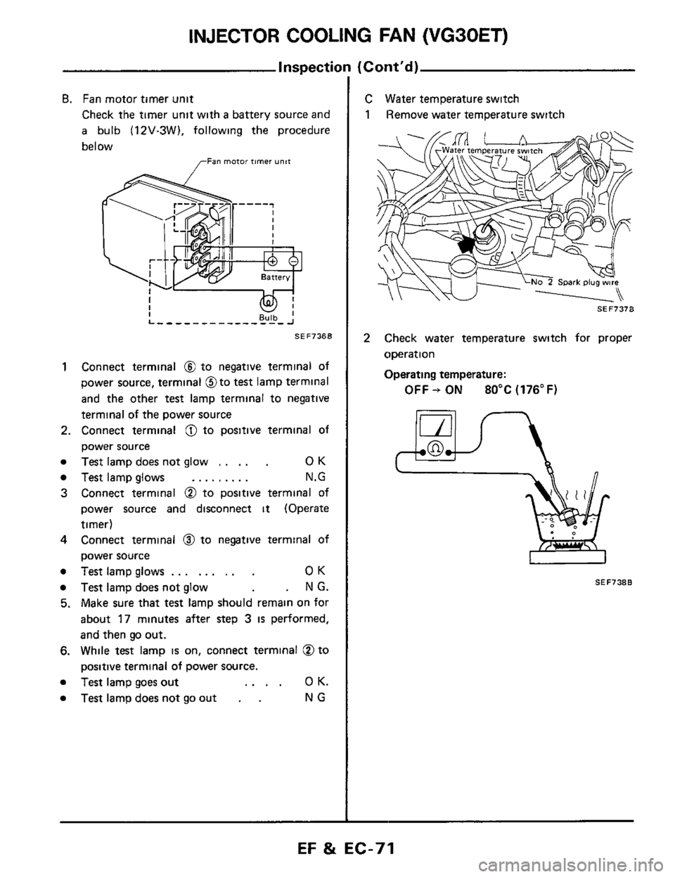
B. Fan motor timer unit
Check the timer unit with a battery source and
a bulb (12V-3W). following the procedure
below
,,-Fan motor timer unit
1 Connect terminal @ to negative terminal of
power source, terminal @to
test lamp terminal
and the other
test lamp terminal to negative
terminal of the power source
2. Connect terminal @ to positive terminal of
power source
Test lamp does not glow ..... OK
Test lamp glows ......... N.G
3 Connect terminal @ to positive terminal of
power source and disconnect it (Operate
timer)
4 Connect terminal @ to negative terminal of
power source
Test lamp glows ......... OK
Test lamp does not glow . N G.
5. Make sure that test lamp should remain on for
about 17 minutes after step 3 is performed,
and then go out.
6. While test lamp is on, connect terminal @to
positive terminal of power source.
Test lamp goes out .... OK.
Test lampdoesnotgoout . . NG
(Corrt'd)
C \Mater temperature switch
1 IRemove water temperature switch
SEF737B
2 Check water temperature switch for proper
operation
Operating temperature:
OFF + ON 80°C (176°F)
SEF738B
EF & EC-71
Page 72 of 79
ZL-33 % A3
NO SI iaieaq iosuas se6 isneqx3
10tl
I
i
3snj
BSELJ3S
Page 73 of 79
PRESSURE REGULATOR CONTROL
I nspi
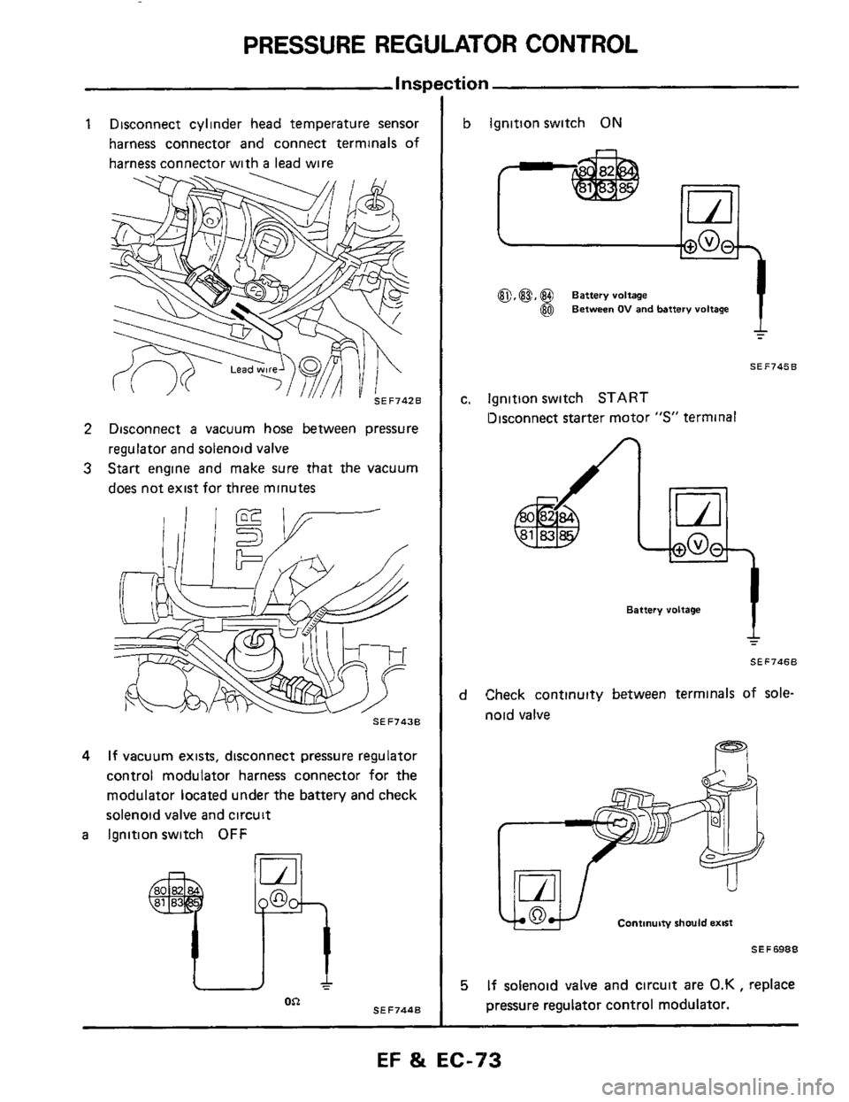
1 Disconnect cylinder head temperature sensor
harness connector and connect terminals of
harness connector with
a lead wire
2 Disconnect a vacuum hose between pressure
regulator and solenoid valve
3 Start engine and make sure that the vacuum
does not exist for three minutes
SEF743B
4 If vacuum exists, disconnect pressure regulator
control modulator harness connector for the
modulator located under the battery and check
solenoid valve and circuit
a Ignition switch OFF
SEF744B OR
b Ignition switch ON
a,@, @ Battery voltage
@ Between OV and battery voltage
SEF745B
c. lgnitlon switch START
13isconnect starter motor "S" terminal
I
Battery voltage
4
SEF7468
d Check continuity between terminals of sole-
noid valve
Continuity should emst
SE F 6988
5 If solenoid valve and circuit are 0.K , replace
pressure regulator control modulator.
-
EF & EC-73
Page 74 of 79
CRANKCASE EMISSION CONTROL SYSTEM
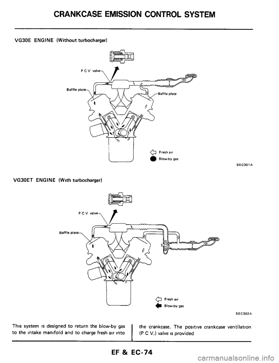
VG30E ENGINE (Without turbocharger)
I "I
e Fresh air
Blow-by gar
VG30ET ENGINE (With turbocharger)
0 Fresh air
Blow-by gar
SEC301A
SEC302A
the crankcase. The positive crankcase ventilation
I (P C V.) valve is provided
This system is designed to return the blow-by gas
to the intake manifold and to charge fresh air into
EF & EC-74
Page 75 of 79
EXHAUST EMISSION CONTROL SYSTEM
-Intake Manifold Vacuum Control-
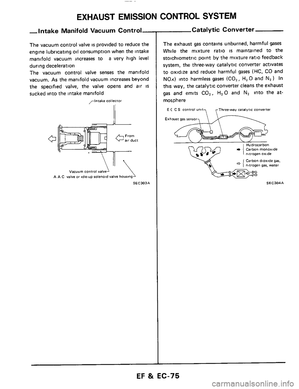
The vacuum control valve is provided to reduce the
engine lubricating oil consumption when the intake
manifold vacuum increases to
a very high level
during deceleration
The vacuum control valve senses
the manifold
vacuum.
As the manifold vacuum increases beyond
the specified valve, the valve opens and
air IS
sucked into the intake manifold
,-intake collecior
\'I
vacuum COntiOl vaivel
A A C valve or de-up rolenoid valve housing
SEC303A
- Catalytic Converter
The exhaust gas contains unburned, harmful gases
While the mixture ratio
is maintained to the
stoichiometric point by the mixture ratio feedback
system, the three-way catalytic converter activates
to oxidize and reduce harmful
gases (HC, CO and
NO.<) into harmless gases (CO,, H, 0 and N2 1 In
this way, the catalytic converter cleans the exhaust
gas and emits CO,, H,O and N, into the at-
mosphere
E ( C S Control unit? yThree-way catalytic Converter
'h
Exhsurt gar renror,
Hydrocarbon Carbon monoxide nltrogen oxide
Carbon dioxide gar. nitrogen gas, water
SEC304A
EF & EC-75
Page 76 of 79
EVAPORATIVE EMISSION CONTROL SYSTEM
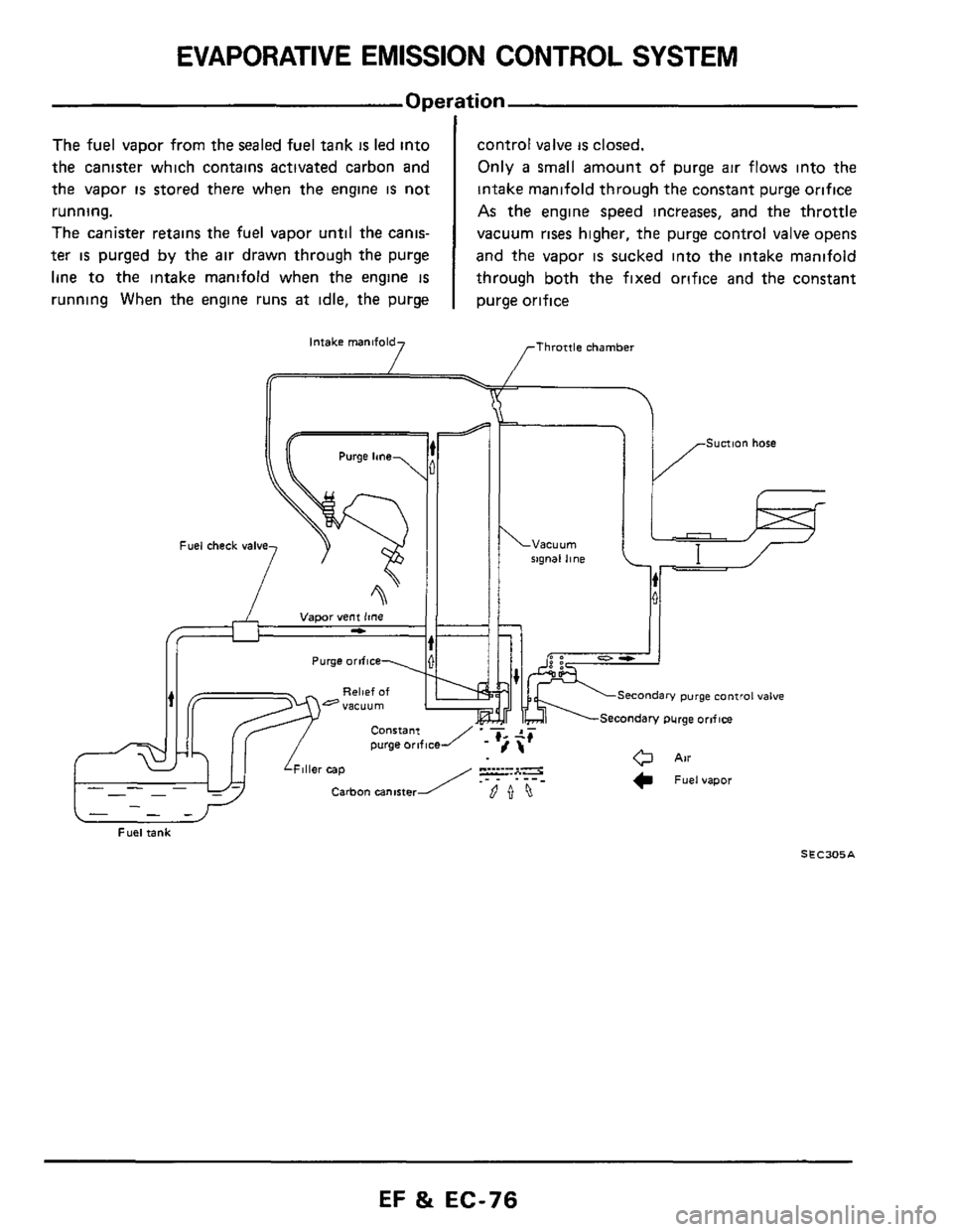
The fuel vapor from the sealed fuel tank is led into
the canister which contains activated carbon and
the vapor
is stored there when the engine is not
running.
The canister retains the fuel vapor until the canis-
ter is purged by the air drawn through the purge
line to the intake manifold when the engine
IS
running When the engine runs at idle, the purge
control valve is closed.
Only
a small amount of purge air flows into the
intake manifold through the constant purge orifice
As the engine speed increases, and the throttle
vacuum
rises higher, the purge control valve opens
and the vapor
is sucked into the intake manifold
through both the fixed orifice and the constant
purge orifice
Intake manifold [Throttle chamber 7 I /F
Sunion hose Purge lane
rxgnal line Fuel check valve
I /F
Sunion hose Purge lane
. ___ -. . . rxgnal line
Purge orifice
i, II
hi II
bl+;fr'
Secondary purge control valve
\Secondary purge orlflce
- -- -
Fuel tank
S E C305 A
EF & EC-76
Page 77 of 79
EVAPORATIVE EMISSION CONTROL SYSTEM
VAPOR VENT LINE
AN
Fuel check valve
SEC306A
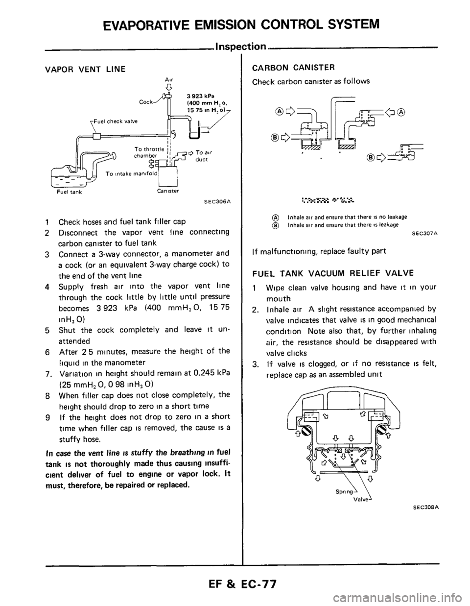
1 Check hoses and fuel tank filler cap
2 Disconnect the vapor vent line connecting
carbon canister to fuel tank
3 Connect a 3-way connector, a manometer and
a cock (or an equivalent 3-way charge cock) to
the end of the vent line
4 Supply fresh air into the vapor vent line
through the cock
little by little untll pressure
becomes
3923 kPa (400 mmH,O, 1575
inH,
0)
5 Shut the cock completely and leave it un-
attended
6 After 25 minutes, measure the height of the
liquid
in the manometer
7. Variation in height should remain
at 0.245 kPa
(25 mmH,
0.0 98 inHl 0)
8 When filler cap does not close completely, the
height should drop to zero in
a short time
9 If the height does not drop to zero in a short
time when filler cap is removed, the cause IS a
stuffy hose.
In case the vent line is stuffy the breathing in fuel
tank
is not thoroughly made thus causing insuffi-
cient deliver of fuel to engine or vapor lock. It
must, therefore, be repaired or replaced.
tion.
CARBON CANISTER
Check carbon canister as follows
I-
UL
@ @)
inhale air and ensure that there IS no leakage inhale air and ensure that there 81 leakage
SEC307A
If malfunctioning, replace faulty part
FUEL TANK VACUUM RELIEF VALVE
1 Wipe clean valve housing and have it in your
mouth
2. Inhale air A slight resistance accompanied by
valve indicates that valve is in good mechanical
condition Note also that, by further inhaling
air, the resistance should be disappeared with
valve clicks
3. If valve is clogged, or if no resistance is felt,
replace cap
as an assembled unit
SEC308A
EF & EC-77
Page 78 of 79
EVAPORATIVE EMISSION CONTROL SYSTEM
I (Cont'd) Inspectic
FUEL CHECK VALVE
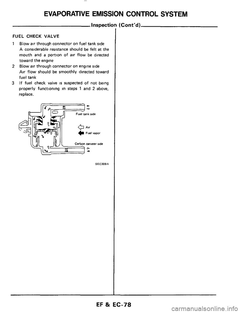
1 Blow air through connector on fuel tank side
A considerable resistance should be felt at the
mouth and
a portion of air flow be directed
toward the engine
Blow
air through connector on engine side
Air flow should be smoothly directed toward
fuel tank
If fuel check valve
is suspected of not being
properly functioning in steps
1 and 2 above,
replace.
2
3
SEC309A
EF 8t EC-78
Page 79 of 79
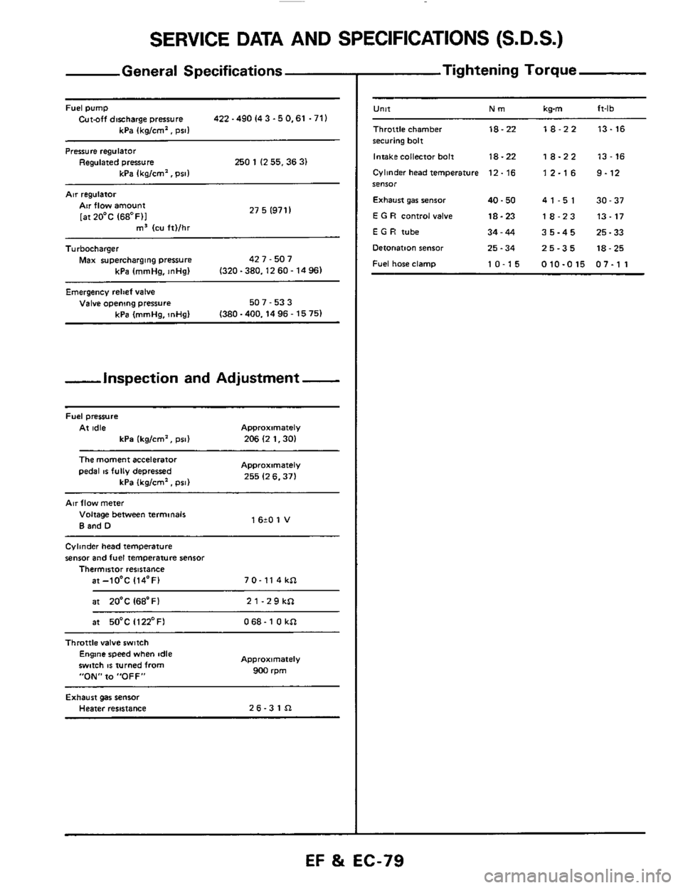
SERVICE DATA AND SPECIFICATIONS (S.D.S.)
General Specifications
Fuel pump Cut-off discharge pressure 422 -490 I4 3 -5 0.61 .71)
kPa (kg/cm'. psi1
Pressure regulator Regulated pressure 250 1 (2 55.36 3) kPa Ikalcm'. Dsll
Air regulatoi
27 5 (971 I Air flow amount
[atZO'C (68OF)I m3 (cu ft)/hr ~~
Turbocharger
Max supercharging pressure 42 7 - 507
kPa (mmHa.
InHal (320-380.1260-1496)
Emergency relief valve Valve opening pressure 507 - 53 3
(380 -400.14 96 - 15 75) kPa (mmHg, InHg)
-inspection and Adjustment -
Fuel pressure
At idle Approximately
kPa (kg/cm', psi) 206 (2 1.30)
The moment accelerator
pedal IS fully depressed Approximately
255 (2 6.371 kPa (kglcm'. psi)
Air flow meter
Voltage between terminals
B and D 1 620 1 V
Cylinder head temperature
sensor and fuel temperature sensor Thermistor resistance
at-lO'C 114'F) 7 0- 11 4 kSl
at 20'C I68'Fl 21-29kSl
at 50°C Il22'FI 068- 1 0 kSl ~~~~
Throttle
valve switch Engine speed when idle
swmh
IS turned from
"ON" to "OFF"
Approximately
900 rpm
Exhaust gas sensor Heater resistance 26-31Sl
- Tightening Torque
-
U"lt Nm kwn ft-lb
Throttle chamber 18-22 18-22 13-16 securing bolt
Intakecollector bolt
18-22 18-22 13-16
Cylinder head temperature 12. 16 1 2.1 6 9.12 SeIlSOr
Exhaust gar senior 40.50 41-51 30-37
E G R control valve 18-23 18-23 13-17
E G H tube 34-44 35-45 25-33
Detonation sensor 25.34 25-35 18-25
Fuel hose clamp 10-15 010-015 07-1 1
EF %i EC-79