Fuel line NISSAN 300ZX 1984 Z31 Engine Fuel And Emission Control System Workshop Manual
[x] Cancel search | Manufacturer: NISSAN, Model Year: 1984, Model line: 300ZX, Model: NISSAN 300ZX 1984 Z31Pages: 79, PDF Size: 2.15 MB
Page 2 of 79
PRECAUTIONS
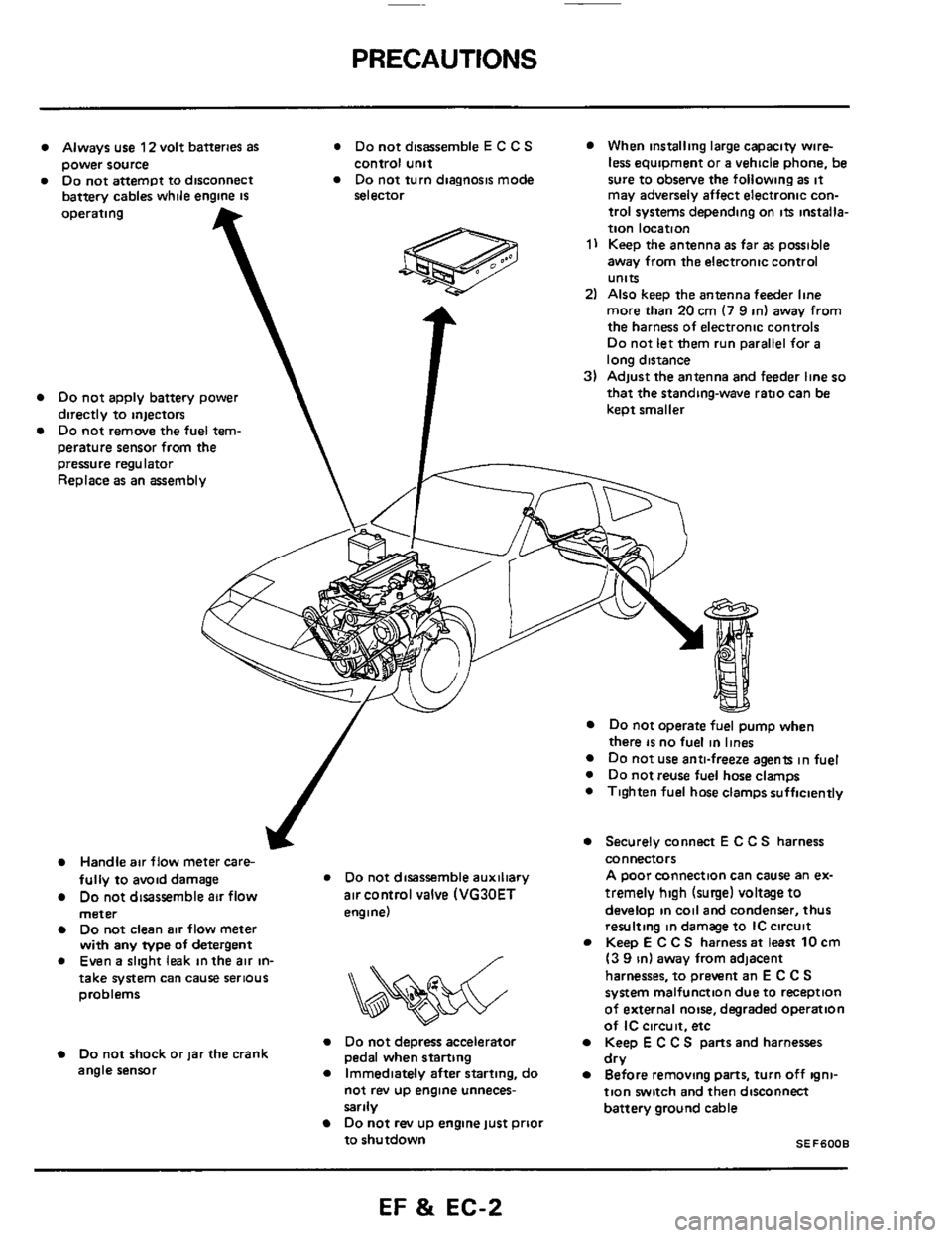
Always use 12 volt batteries as * Do not disassemble E C C S When installing large capacity wire-
Do not attempt to disconnect Do not turn diagnosis mode sure to obsetve the following as it power source
battery cables while engine
IS
control unit
selector less equipment or a vehicle phone, be
may adversely affect electronic con-
operating
Do not apply battery power
directly to injectors
Do not remove the fuel tem-
perature sensor from
the T
pressure regulator
Replace as an assembly
trol systems depending on its installa-
tion location
1) Keep the antenna as far as possible
away from the electronic control
units
2) Also keep the antenna feeder line
more than
20 cm (7 9 in) away from
the harness of electronic controls
Do not let them run parallel for a
long distance
3) Adjust the antenna and feeder line so
that the standing-wave ratio can be
keot smaller
J
Handle air flow meter care-
fully to avoid damage * Do not disassemble auxiliary
Do not disassemble air flow air control valve (VG30ET
meter engine)
Do not clean air flow meter
with any type of detergent
0 Even a slight leak in the air in- /
&&%$$?&
take system can cause serious
problems
Do not depress accelerator Do not shock or jar the crank
angle sensor
Immediately after starting, do
pedal when starting
not rev
up engine unneces-
sarily
Do not rev up engine just prioi
to shutdown
Do not operate fuel pump when
there is no fuel in lines Do not use anti-freeze agents in fuel
0 Do not reuse fuel hose clamps
0 Tighten fuel hose clamps sufficiently
Securely connect E C C S harness
connectors
A poor connection can cause an ex-
tremely
high (surge) voltage to
develop in coil and condenser, thus
resulting in damage to IC circuit
Keep
E C C S harness at least 10 cm
(3 9 in) away from adjacent
harnesses, to prevent an
E C C S
system malfunction due to reception
of external noise, degraded operation
of
IC circuit. etc
Keep E C C S parts and harnesses
Before removing parts, turn off igni-
tion switch and then disconnect
battery ground cable dry
SEF6008
EF & EC-2
Page 10 of 79
FUEL FLOW SYSTEM DESCRIPTION
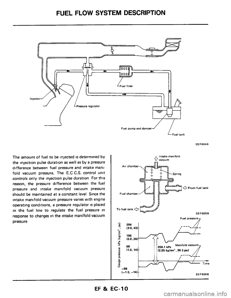
The amount of fuel to be injected is determined by
the injection pulse duration
as well as by a pressure
difference between fuel pressure and intake mani-
fold vacuum pressure. The
E.C C.S. control unit
controls only the injection pulse duration For this
reason,
the pressure difference between the fuel
pressure and intake manifold vacuum pressure
should be maintained
at a constant level Since the
intake manifold vacuum pressure varies with engine
operating conditions,
a pressure regulator IS placed
in the fuel line to regulate the fuel pressure in
response to changes
in the intake manifold vacuum
pressure
Fuel pump and damper
’ iFueirank
SEF604B
intake manifold 0 vacuum
a From fuel tank
Fuel chamber
SEF605B
Fuel presswe
EF & EC-10
Page 63 of 79
FUEL SYSTEM INSPECTION
Releasing Fuel Pressure
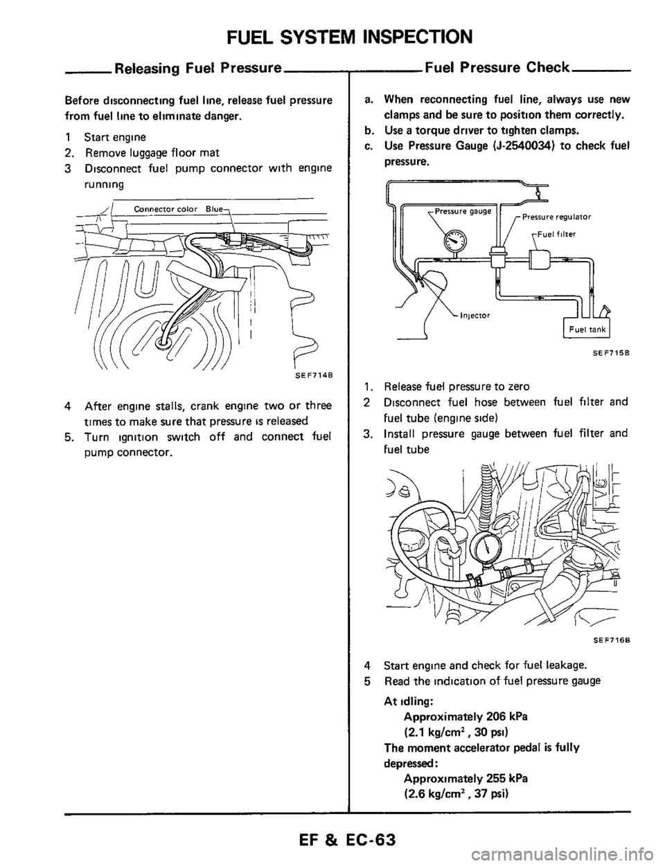
Before disconnecting fuel line, release fuel pressure
from fuel line to eliminate danger.
1 Start engine
2. Remove luggage floor mat
3 Disconnect fuel pump connector with engine
running
SEF7148
4 After engine stalls, crank engine two or three
times to make sure that pressure
IS released
5. Turn ignition switch off and connect fuel
pump connector.
--Fuel Pressure Check
a. When reconnecting fuel line, always use new
clamps and be sure to position them correctly.
b. Use a torque driver to tighten clamps.
c.
Use Pressure Gauge (5-2540034) to check fuel
pressure.
I Fuel tank I -A
SEF7158
1. Release fuel pressure to zero
2 Disconnect fuel hose between fuel filter and
Fuel tube (engine side1
3. Install pressure gauge between fuel filter and
Fuel tube
SEF7168
4
5
Start engine and check for fuel leakage.
Read the indication of fuel pressure gauge
At idling:
Approximately 206 kPa
(2.1 kg/cm2, 30 psi)
The moment accelerator pedal is fully
depressed
:
Approximately 255 kPa
(2.6 kg/cm2, 37 psi)
EF & EC-63
Page 76 of 79
EVAPORATIVE EMISSION CONTROL SYSTEM
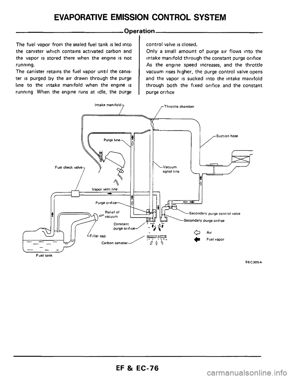
The fuel vapor from the sealed fuel tank is led into
the canister which contains activated carbon and
the vapor
is stored there when the engine is not
running.
The canister retains the fuel vapor until the canis-
ter is purged by the air drawn through the purge
line to the intake manifold when the engine
IS
running When the engine runs at idle, the purge
control valve is closed.
Only
a small amount of purge air flows into the
intake manifold through the constant purge orifice
As the engine speed increases, and the throttle
vacuum
rises higher, the purge control valve opens
and the vapor
is sucked into the intake manifold
through both the fixed orifice and the constant
purge orifice
Intake manifold [Throttle chamber 7 I /F
Sunion hose Purge lane
rxgnal line Fuel check valve
I /F
Sunion hose Purge lane
. ___ -. . . rxgnal line
Purge orifice
i, II
hi II
bl+;fr'
Secondary purge control valve
\Secondary purge orlflce
- -- -
Fuel tank
S E C305 A
EF & EC-76
Page 77 of 79
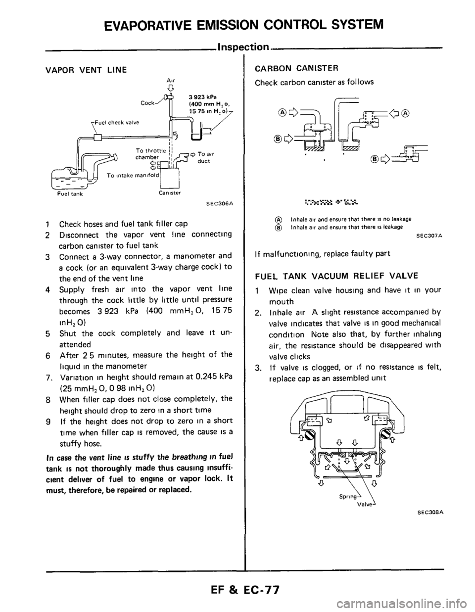
EVAPORATIVE EMISSION CONTROL SYSTEM
VAPOR VENT LINE
AN
Fuel check valve
SEC306A
1 Check hoses and fuel tank filler cap
2 Disconnect the vapor vent line connecting
carbon canister to fuel tank
3 Connect a 3-way connector, a manometer and
a cock (or an equivalent 3-way charge cock) to
the end of the vent line
4 Supply fresh air into the vapor vent line
through the cock
little by little untll pressure
becomes
3923 kPa (400 mmH,O, 1575
inH,
0)
5 Shut the cock completely and leave it un-
attended
6 After 25 minutes, measure the height of the
liquid
in the manometer
7. Variation in height should remain
at 0.245 kPa
(25 mmH,
0.0 98 inHl 0)
8 When filler cap does not close completely, the
height should drop to zero in
a short time
9 If the height does not drop to zero in a short
time when filler cap is removed, the cause IS a
stuffy hose.
In case the vent line is stuffy the breathing in fuel
tank
is not thoroughly made thus causing insuffi-
cient deliver of fuel to engine or vapor lock. It
must, therefore, be repaired or replaced.
tion.
CARBON CANISTER
Check carbon canister as follows
I-
UL
@ @)
inhale air and ensure that there IS no leakage inhale air and ensure that there 81 leakage
SEC307A
If malfunctioning, replace faulty part
FUEL TANK VACUUM RELIEF VALVE
1 Wipe clean valve housing and have it in your
mouth
2. Inhale air A slight resistance accompanied by
valve indicates that valve is in good mechanical
condition Note also that, by further inhaling
air, the resistance should be disappeared with
valve clicks
3. If valve is clogged, or if no resistance is felt,
replace cap
as an assembled unit
SEC308A
EF & EC-77