air conditioning NISSAN 300ZX 1984 Z31 Heather And Air Conditioner Workshop Manual
[x] Cancel search | Manufacturer: NISSAN, Model Year: 1984, Model line: 300ZX, Model: NISSAN 300ZX 1984 Z31Pages: 38, PDF Size: 1.15 MB
Page 2 of 38

GENERAL DESCRIPTION
Continuously Variable Air Flow Control
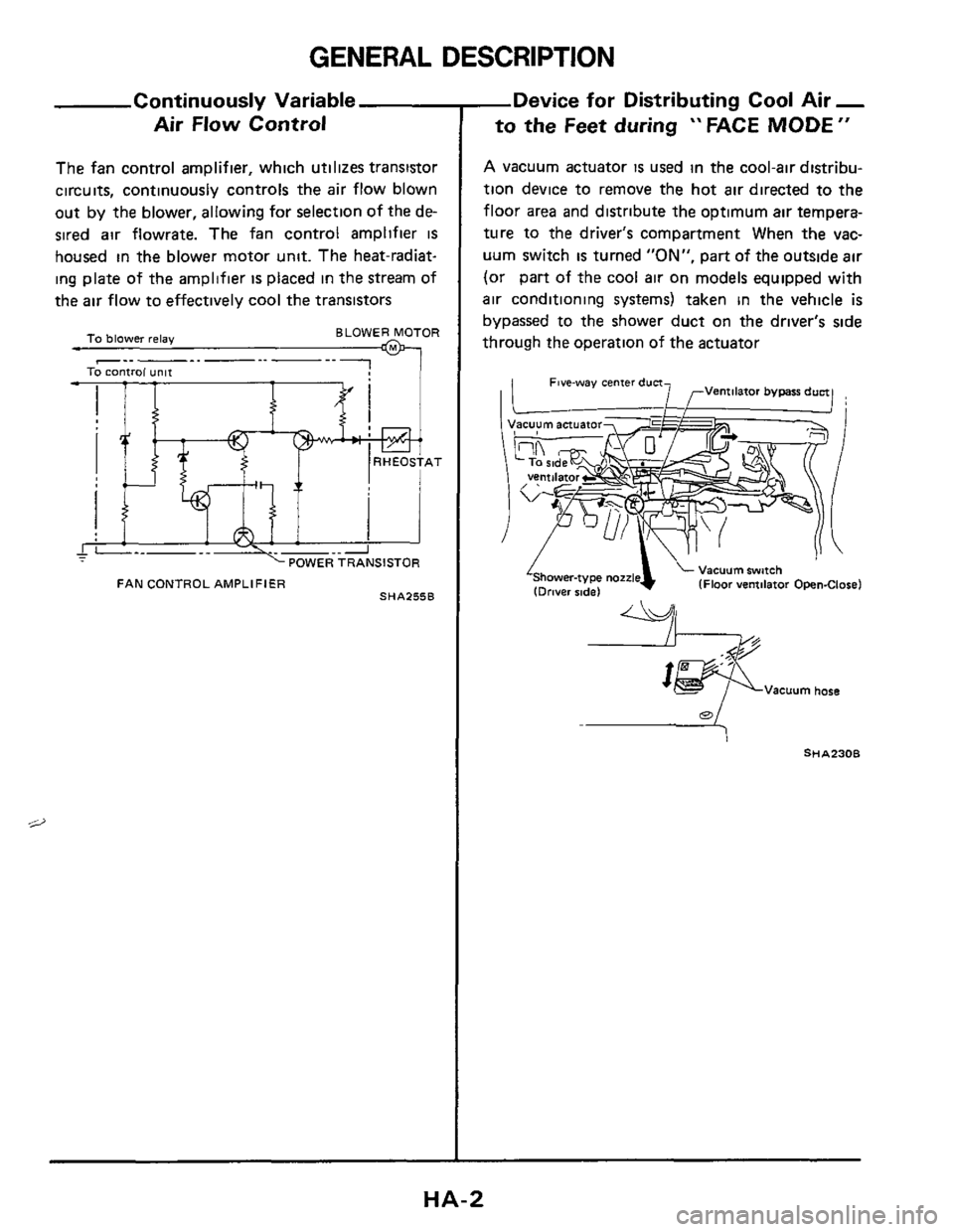
The fan control amplifier, which utilizes transistor
circuits, continuously controls the air flow blown
out
by the blower, allowing for selection of the de-
sired air flowrate. The fan control amplifier
IS
housed in the blower motor unit. The heat-radiat-
ing plate of the amplifier
is placed in the stream of
the air flow to effectively cool the transistors
BLOWER MOTOR To blower relay M
AT AT
I - I __4;-..2 POWER TRANSISTOR
FAN CONTROL AMPLIFIER SHA255B
-Device for Distributing Cool Air -
to the Feet during " FACE MODE "
A vacuum actuator is used in the cool-air distribu-
tion device to remove the hot
air directed to the
floor area and distribute the optimum air tempera-
ture to the driver's compartment When the vac-
uum switch
is turned "ON", part of the outside air
(or part of the cool air on models equipped with
air conditioning systems) taken in the vehicle is
bypassed to the shower duct on the driver's side
through the operation of the actuator
4 Vacuum swfch IFloor ventilator Open-Close) 'Shower-ty pe nozzle (Driver sidel
Vacuum hose
a
HA-2
Page 10 of 38

DESCRIPTION-Air Conditioner (Manual)
Refrigerant Leak Warning System
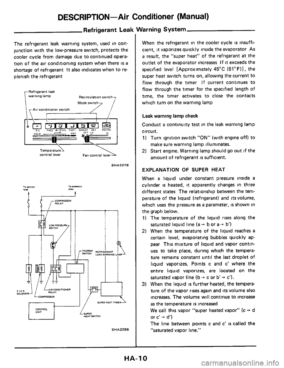
The refrigerant leak warning system, used in con-
junction with the low-pressure switch, protects the
cooler cycle from damage due to continued opera-
tion of the
air conditioning system when there is a
shortage of refrigerant
It also indicates when to re-
plenish the refrigerant
Refrigerant leak
warnmg lamp Recirculation switch
Air conditioner switch
control lever
SHA227B
I ll I
SHA2286
When the refrigerant in the cooler cycle is insuffi-
cient,
it vaporizes quickly inside the evaporator As
a result, the "super heat" of the refrigerant at the
outlet of the evaporator increases
If it exceeds the
specified level [Approximately 45°C
(8l0F)1, the
super heat switch turns on, allowing the current to
flow through the timer If current continues to
flow through the timer for the specified length of
time, the timer activates to close the contacts
which turn on the warning lamp
Leak warning lamp check
Conduct a continuity test in the leak warning lamp
circuit.
1) Turn ignition switch "ON" (with engine off) to
make sure warning lamp illuminates.
2) Start engine. Warning lamp should go out if the
amount of refrigerant
is sufficient.
EXPLANATION OF SUPER HEAT
When a liquid under constant pressure inside a
cylinder is heated, it apparently changes in three
different
states The relationship between the tem-
perature of the liquid (refrigerant) and
its volume,
which
uses the pressure as a parameter, is shown in
the graph below.
1) The temperature of the liquid rises along the
saturated liquid line (a -+ b or a + b')
2) When the temperature of the liquid reaches a
certain level, evaporating bubbles quickly ap-
pear This mixture of liquid and vapor contin-
ues to take place, during which the tempera-
ture remains constant until the
last droplet of
liquid vaporizes. Points c and c' where the
entire liquid vaporizes, are located on the
saturated vapor line (b
+ c or b -+ c').
3) When the liquid is further heated, the tempera-
ture of the vapor
rises again and its volume also
increases.
The volume will continue to increase
as the temperature is increased
We call this vapor "super heated vapor" (c + d
or c'
+ d')
The line between points c and c'
is called the
"saturated vapor line."
HA-I 0
Page 22 of 38

PIPING, COMPRESSOR MOUNTING AND F.I.C.D.
Idle Speed Adju
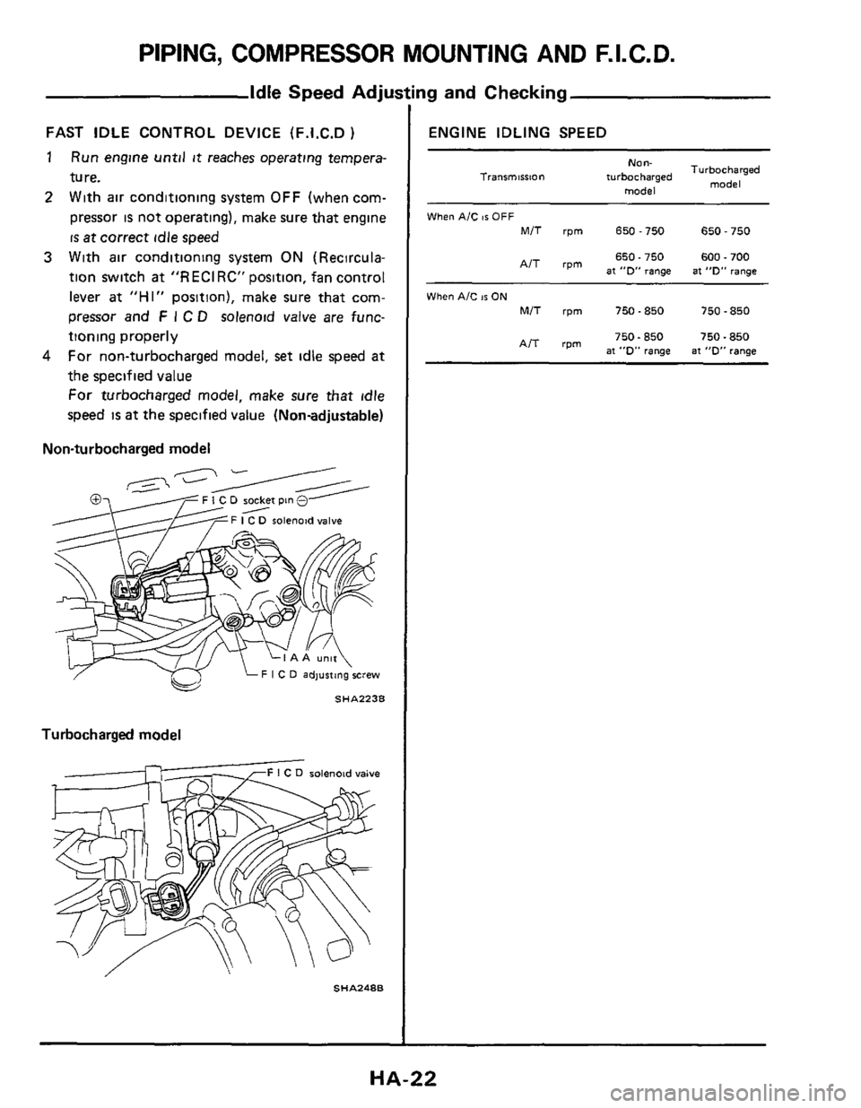
FAST IDLE CONTROL DEVICE (F.1.C.D )
1
2
Run engine until it reaches operating tempera-
ture.
With air conditioning system
OFF (when com-
pressor
is not operating), make sure that engine
is at correct idle speed
3 With air conditioning system ON (Recircula-
tion switch
at "RECIRC" position, fan control
lever
at "HI" position), make sure that com-
pressor and
F I C D solenoid valve are func-
tioning properly
For non-turbocharged model,
set idle speed at
the specified value
For turbocharged model, make sure that idle
speed is at the specified value (Nonadjustable)
4
Non-turbocharged model
F I C D socket pin 0
solenoid valve
Turbocharged model
solenoid valve
SHA248B
ng and Checking
ENGINE IDLING SPEED
NO"-
model
Turbocharged
model Tranrmission turbocharged
When AIC 86 OFF
MIT rpm 650-750 650 - 750
650.750 600.700 AIT rpm at "0" range at "D" range
When AIC IS ON
MIT rpm 750-850 750 - 850
750.850 750.850 AIT rpm at "D" range at "0" range
HA-22