NISSAN 300ZX 1984 Z31 Automatic Transmission Workshop Manual
Manufacturer: NISSAN, Model Year: 1984, Model line: 300ZX, Model: NISSAN 300ZX 1984 Z31Pages: 99, PDF Size: 3.09 MB
Page 1 of 99
--
AUTOMATIC TRANSMISSIOB
SECTION AT
CONTENTS
DESCRIPTION OF E4N71B ..... ............ AT- 2
GENERAL SERVICE NOTICE
.. .. ........ AT- 4
ON-VEHICLE SERVICE
. .. .. .... ......... AT-10
REMOVAL AND INSTALLATION..
t. ... .. .. .... AT-1 8
MAJOR OVERHAUL
. ... ... ... ...... AT-20
DISASSEMBLY
... ....................... AT-22
REPAIR
FOR COMPONENT PARTS . .. ...... .. ........ AT-28
ASSEMBLY
...... .. ....... .............. AT-49
TROUBLE-SHOOTING AND DIAGNOSES
. .......... ... AT-63
SERVICE DATA AND SPECIFICATIONS
(S D.S) .... ............. AT-95
SPECIAL SERVICE TOOLS
........................... AT-99
Page 2 of 99

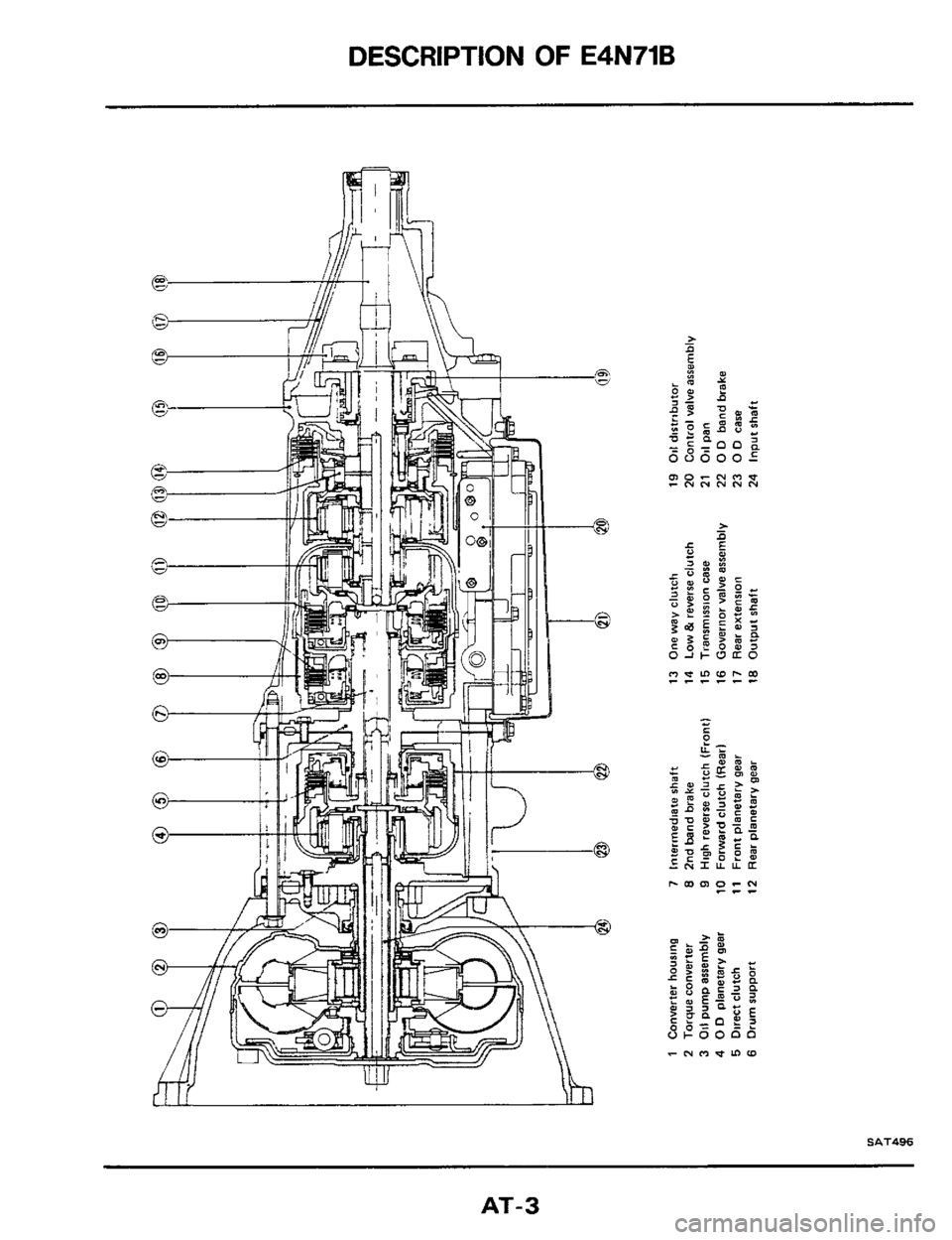
DESCRIPTION OF E4N71B
I
The Model E4N71B automatic transmission is the
latest addition to Niaan's lineup
of transmissions.
This transmission
is based on the model L4N71B
(mounted on the 1983 model 810), and can pro-
vide lockup of
all forward speeds (1st to 4th speed)
by electronic control.
By use of a microcomputer, the electronic-control-
led lockup system permits lockup of
all forward
speeds (1st to 4th speed)
Either shifting pattern ("standard" or "power")
is
automatically selected by programs set in the
lockup control unit depending on the speed
at
which the accelerator pedal is depressed These
programs are
set in response to the vehicle speed
and throttle position
rlnhibitor switch \Lockup control unit
/;?\I!
LPower Shift switch and mdtcator
Stop lamp rwlrch
\Kickdown switch
Downshift solenoid
Shift switch and low temperature sensor
Throttle valve rwitchl 0 indicator
Lockup solenoid 0 D cancel solenoid
SAT7M
AT-2
Page 3 of 99
DESCRIPTION OF E4N71B
AT-3
Page 4 of 99

GENERAL SERVICE NOTICE
Repai
Before proceeding with disassembly, thorough-
ly clean the outside of the transmission It IS
important to prevent the internal parts of the
transmission from becoming contaminated by
dirt or other foreign matter.
Disassembly should
be done in a clean work
area. Use
a nylon cloth or paper towel for wiping
parts clean. Common
shop rags can leave lint
that might interfere with the transmission's
operation.
When disassembling parts, be sure to place
them in order
in parts rack so they can be put
back in the unit
in their proper positions
All parts should be carefully cleaned with a
general purpose, non.flammable solvent before
inspection or reassembly.
Gaskets,
seals, and O-rings should be replaced.
It is also very important to perform functional
tests whenever it is designated.
The valve body contains many precision parts
Contri
CONTROL VALVE UPPER BODY
3rd4th shift valve7
Pressure I
Uotes
and requires extreme care when parts are
removed and serviced. Place removed parts on
a parts rack so they can be put back in the
valve body in the same positions and
se-
quences. Care will also prevent springs and
small parts from becoming scattered or
lost
Before assembly, apply a coat of recommended
A
T.F. to all parts Vaseline may be applied to
O-rings and
seals. Do not use any grease.
Care should be taken to avoid damaging
O-rings, seals and
gaskets when assembling
Abbreviations used throughout this section stand
for the following.
A.T.F. ... Automatic transmission fluid
D, ........ Drive range 1st gear
D, .... ... Drive range 2nd gear
D, . . ... Drive range 3rd gear
D4 ........ Drive range 4th gear
0.D . .... Overdrive
1, ....... . 1 range 2nd gear
1, . . .... 1 range lstgear
Valve
Vacuum throttle valve
f rThrottle back-up valve
1st 2nd shift valve
2nd3rd shift valve
Second lock valve -i
SAT742
AT-4
Page 5 of 99

GENERAL SERVICE NOTICE
Control Valve (Cont'd)
CONTROL VALVE LOWER BODY
3rd-2nd timing valve
f --
, /
-7, - _- _:. - A=----* --
-
SAT705
Lock-up Control Valve and O.D. Cancel Valve
Retaining pin1
SAT498
AT-5
Page 6 of 99
GENERAL SERVICE NOTICE
Oil Channel
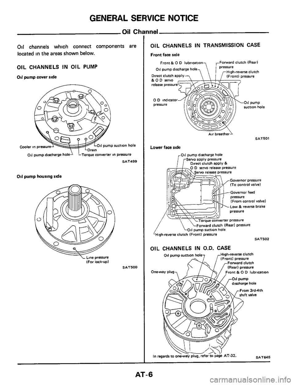
Oil channels which connect components are
located in the
areas shown below.
OIL CHANNELS IN OIL PUMP
Oil pump cover ride
11 pump suction hole Cooler in pressure
011 pump discharge hold LTorque converter in pressure
Oil pump housing ride
ne oressure
SAT499
SAT500
OIL CHANNELS IN TRANSMISSION CASE
Front face rlde
Front & 0 D lubrication Forward clutch (Rear1
gh-reverse clutch
011 pump discharge hole
Direct clutch apply &OD sew0 release pressure
0 0 indicator pressure
SAT501
Lower face side
Governor pressure (To control valve)
Governor feed
(From control
valve)
LOW & reverse brake
High-reverse clutch IFrontl pressure SAT502
ii
OIL CHANNELS IN O.D. CASE
011 pump suction hole Hlgh-reverse clutch (Front1 pressure
Forward clutch
(Rear) Oresure
ront & 0 D lubrication
SAT645 In regards to oneway plug. refer to page AT-32.
AT-6
Page 7 of 99

GENERAL SERVICE NOTICE
I (Cont'd) Oil Cham
OIL CHANNELS IN DRUM SUPPORT OIL CHANNELS IN CONVERTER HOUSING
To lock-up ~ontrol valve
rDrain (E4N71Bl
clutch (Front)
Forward clutch
clutch pressure Front & 0 0 lubrmtmn
SAT706
3peration Mechanic:
In the E4N71B and 4N71B automatic transmission, each part operates as shown in the following table at
each gear select position
'arking
pawl
Htgh-
'everse
Front) Forward clutch (Rear) 0 D band servo Direct
clutch Range -
Release
ON ON
1 Reverse 1 ON 1 ION) ON
+-
ON I
I Neutral I ON I (ON) ON
T-
ON
-
ON
-
ON
ON
JT
I ION
'34
(0 D 1 ON I ON
Second I ON I (ON) ON
1 ON I (ON) 12
(Second) ON ON I ON
ON ord ON I I ON
The low & reverse brake IS applied In "1 I" range to prevent free wheeling when coasting and allows engine braking.
AT-7
Page 8 of 99
GENERAL SERVICE NOTICE
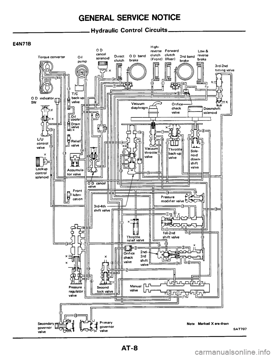
Hydraulic Control Circuits
E4N71B
0 S
Primary
governor governor
valve x valve
Nota Marked X are drain
SAT707
AT-8
Page 9 of 99

GENERAL SERVICE NOTICE
Hydraulic Control Circuits (Cont'd)
High- 0 D rwerse Forward 2"d Low& OD cancel
4N71B
Torque converter
Note Marked X are dram
-
SAT708
AT-9
Page 10 of 99
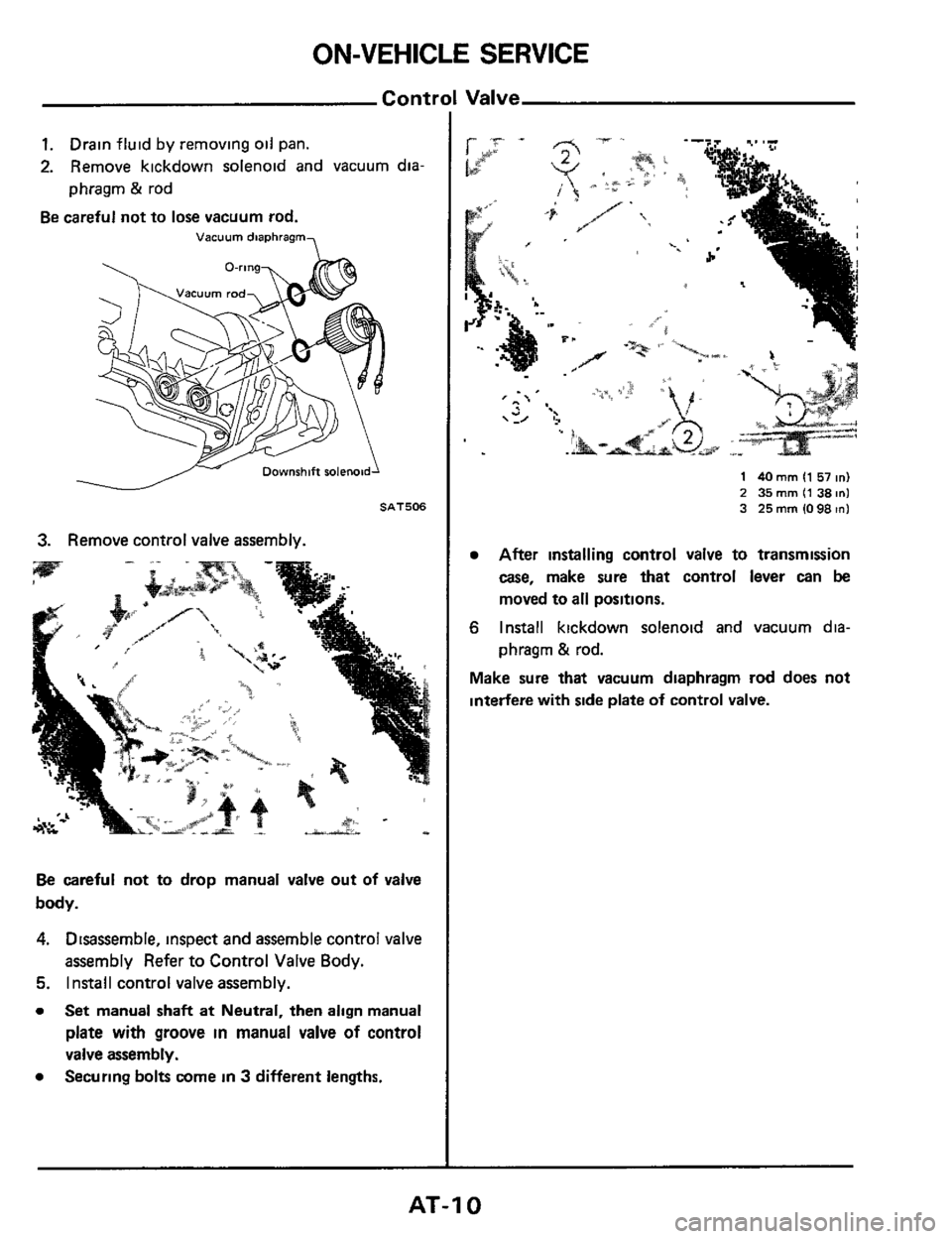
ON-VEHICLE SERVICE
Contrl
1. Drain fluid by removing oil pan.
2. Remove kickdown solenoid and vacuum dia
phragm
23 rod
Be careful not to lose vacuum rod.
Vacuum diaphragm
SAT506
3. Remove control valve assembly.
Be careful not to drop manual valve out of valve
body.
4. Disassemble, inspect and assemble control valve
assembly Refer to Control Valve Body.
5. Install control valve assembly.
0 Set manual shaft at Neutral, then align manual
plate with groove in manual valve of control
valve assembly.
Securing bolts come
in 3 different lengths. 0
1 40 mm I1 51 in) 2 35 mm (1 38 in1 3 25mm1098mI
After installing control valve to transmission
case, make sure that control lever can be
moved to all positions.
6 Install kickdown solenoid and vacuum dia-
phragm
& rod.
Make sure that vacuum diaphragm rod does not
interfere with side plate
of control valve.
AT-I 0