NISSAN 350Z 2007 Z33 Automatic Transmission Workshop Manual
Manufacturer: NISSAN, Model Year: 2007,
Model line: 350Z,
Model: NISSAN 350Z 2007 Z33
Pages: 312, PDF Size: 10.64 MB
NISSAN 350Z 2007 Z33 Automatic Transmission Workshop Manual
350Z 2007 Z33
NISSAN
NISSAN
https://www.carmanualsonline.info/img/5/755/w960_755-0.png
NISSAN 350Z 2007 Z33 Automatic Transmission Workshop Manual
Trending: light, engine oil capacity, wheel torque, change time, ignition, warning light, reverse
Page 251 of 312
OVERHAUL
AT-251
D
E
F
G
H
I
J
K
L
MA
B
AT
Revision: 2006 November2007 350Z
10. Revolution sensor 11. Parking gear 12. Output shaft
13. Bearing race 14. Needle bearing 15. Manual plate
16. Parking rod 17. Manual shaft oil seal 18. Manual shaft
19. O-ring 20. Band servo anchor end pin 21. Detent spring
22. Spacer 23. Seal ring 24. Snap ring
25. Return spring 26. O-ring 27. Servo assembly
28. Snap ring 29. Sub-harness 30. Control valve with TCM
31. Bracket 32. A/T fluid temperature sensor 2 33. Clip
34. Oil pan mounting bolt 35. Oil pan 36. Magnet
37. Drain plug 38. Drain plug gasket 39. Oil pan gasket
40. Terminal cord assembly 41. O-ring 42. Retaining pin
43. Transmission case
Refer to GI section to make sure icons (symbol marks) in the figure. Refer to GI-11, "
Components" .
However, refer to the following for others.
*: Apply Genuine Anaerobic Liquid Gasket or equivalent. Refer to GI-45, "Recommended Chemical Products and Sealants" .
Page 252 of 312
AT-252
OVERHAUL
Revision: 2006 November2007 350Z
Oil ChannelNCS00099
SCIA6387E
Page 253 of 312
OVERHAUL
AT-253
D
E
F
G
H
I
J
K
L
MA
B
AT
Revision: 2006 November2007 350Z
Locations of Adjusting Shims, Needle Bearings, Thrust Washers and Snap
Rings
NCS0009A
SCIA8291E
Snap ring Needle bearing
Item number Outer diameter mm (in) Item number Outer diameter mm (in)
1 67.5 (2.657) 10 80 (3.15)
2 182.4 (7.181) 11 77 (3.03)
3 171.5 (6.751) 12 77 (3.03)
4 70.5 (2.775) 13 47 (1.85)
5 169 (6.653) 14 84 (3.31)
6 134.3 (5.287) 15 84 (3.31)
7 180.5 (7.106) 16 92 (3.62)
8 181 (7.125) 17 60 (2.36)
9 48.4 (1.905) 18 63 (2.48)
— — 19 92 (3.62)
Page 254 of 312
AT-254
OVERHAUL
Revision: 2006 November2007 350Z
— — 20 65 (2.56)
— — 21 60 (2.36)Snap ring Needle bearing
Item number Outer diameter mm (in) Item number Outer diameter mm (in)
Page 255 of 312
DISASSEMBLY
AT-255
D
E
F
G
H
I
J
K
L
MA
B
AT
Revision: 2006 November2007 350Z
DISASSEMBLYPFP:31020
DisassemblyNCS0009B
CAUTION:
Do not disassemble parts behind Drum Support. Refer to AT- 1 7 , "
Cross-sectional View" .
1. Drain ATF through drain hole.
2. Remove torque converter by holding it firmly and turing while
pulling straight out.
3. Check torque converter one-way clutch using check tool as
shown at figure.
a. Insert check tool into the groove of bearing support built into
one-way clutch outer race.
b. When fixing bearing support with check tool, rotate one- way
clutch spline using screwdriver.
c. Check that inner race rotates clockwise only. If not, replace
torque converter assembly.
4. Remove tightening bolts ( ) for converter housing and trans-
mission case.
5. Remove converter housing from transmission case.
CAUTION:
Be careful not to scratch converter housing.
SCIA5010E
SCIA3171E
SCIA8096E
Page 256 of 312
AT-256
DISASSEMBLY
Revision: 2006 November2007 350Z
6. Remove O-ring from input clutch assembly.
7. Remove tightening bolts for oil pump assembly and transmis-
sion case.
8. Attach the sliding hammers to oil pump assembly and extract it
evenly from transmission case.
CAUTION:
�Fully tighten sliding hammer screw.
�Make sure that bearing race is installed to the oil pump
assembly edge surface.
9. Remove O-ring from oil pump assembly.
SCIA5011E
SCIA2300E
SCIA5312E
SCIA5172E
Page 257 of 312
DISASSEMBLY
AT-257
D
E
F
G
H
I
J
K
L
MA
B
AT
Revision: 2006 November2007 350Z
10. Remove bearing race from oil pump assembly.
11. Remove needle bearing from front sun gear.
12. Remove front sun gear assembly from front carrier assembly.
NOTE:
Remove front sun gear by rotating left/right.
13. Remove seal rings from input clutch assembly.
14. Remove front carrier assembly from rear carrier assembly. (With
input clutch assembly and rear internal gear.)
CAUTION:
Be careful to remove it with needle bearing.
SCIA6529E
SCIA2808E
SCIA5014E
SCIA2470E
SCIA5015E
Page 258 of 312
AT-258
DISASSEMBLY
Revision: 2006 November2007 350Z
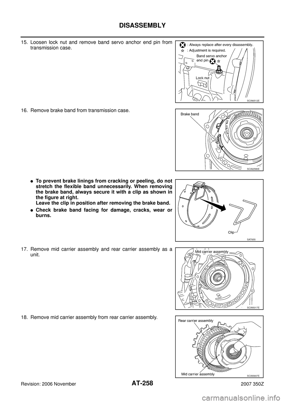
15. Loosen lock nut and remove band servo anchor end pin from
transmission case.
16. Remove brake band from transmission case.
�To prevent brake linings from cracking or peeling, do not
stretch the flexible band unnecessarily. When removing
the brake band, always secure it with a clip as shown in
the figure at right.
Leave the clip in position after removing the brake band.
�Check brake band facing for damage, cracks, wear or
burns.
17. Remove mid carrier assembly and rear carrier assembly as a
unit.
18. Remove mid carrier assembly from rear carrier assembly.
SCIA6512E
SCIA2580E
SAT655
SCIA5017E
SCIA5697E
Page 259 of 312
DISASSEMBLY
AT-259
D
E
F
G
H
I
J
K
L
MA
B
AT
Revision: 2006 November2007 350Z
19. Remove needle bearing (front side) from mid carrier assembly.
20. Remove needle bearing (rear side) from mid carrier assembly.
21. Remove bearing race from rear carrier assembly.
22. Remove needle bearing from rear carrier assembly.
23. Remove mid sun gear assembly, rear sun gear assembly and
high and low reverse clutch hub as a unit.
CAUTION:
Be careful to remove then with bearing race and needle
bearing.
SCIA2805E
SCIA2804E
SCIA5175E
SCIA2803E
SCIA5018E
Page 260 of 312
AT-260
DISASSEMBLY
Revision: 2006 November2007 350Z
24. Remove high and low reverse clutch assembly from direct clutch
assembly.
CAUTION:
Make sure that needle bearing is installed to high and low
reverse clutch assembly edge surface.
25. Remove direct clutch assembly from reverse brake.
26. Remove needle bearing from drum support.
27. Remove snap ring from A/T assembly harness connector.
28. Push A/T assembly harness connector.
CAUTION:
Be careful not to damage connector.
SCIA2306E
SCIA5019E
SCIA5198E
SCIA5021E
SCIA5022E
Trending: window, engine, tires, radiator cap, OBD port, clock, wiring


— — 21 60 (2.36)Snap ring Needle bearing
Item number Outer diameter mm (in) Item number Outer diameter mm (in)")


 from mid carrier assembly.
20. Remove needle bearing (rear side) from mid carrier a")
