NISSAN 350Z 2007 Z33 Automatic Transmission Workshop Manual
Manufacturer: NISSAN, Model Year: 2007,
Model line: 350Z,
Model: NISSAN 350Z 2007 Z33
Pages: 312, PDF Size: 10.64 MB
NISSAN 350Z 2007 Z33 Automatic Transmission Workshop Manual
350Z 2007 Z33
NISSAN
NISSAN
https://www.carmanualsonline.info/img/5/755/w960_755-0.png
NISSAN 350Z 2007 Z33 Automatic Transmission Workshop Manual
Trending: oil type, brakes, wiring diagram, lock, relay, fuse box location, ECO mode
Page 271 of 312
REPAIR FOR COMPONENT PARTS
AT-271
D
E
F
G
H
I
J
K
L
MA
B
AT
Revision: 2006 November2007 350Z
REPAIR FOR COMPONENT PARTSPFP:00000
Oil PumpNCS0009C
COMPONENTS
DISASSEMBLY
1. Remove oil pump housing from oil pump cover.
2. Remove oil pump housing oil seal using a flat-bladed screw-
driver.
CAUTION:
Be careful not to scratch oil pump housing.
1. O-ring 2. Oil pump cover 3. O-ring
4. Oil pump housing 5. Oil pump housing oil seal
SCIA5323E
SCIA6388E
SCIA2840E
Page 272 of 312
AT-272
REPAIR FOR COMPONENT PARTS
Revision: 2006 November2007 350Z
3. Remove O-ring from oil pump housing.
4. Remove O-ring from oil pump cover.
ASSEMBLY
1. Install O-ring to oil pump cover.
CAUTION:
�Do not reuse O-ring.
�Apply ATF to O-ring.
2. Install O-ring to oil pump housing.
CAUTION:
�Do not reuse O-ring.
�Apply ATF to O-ring.
SCIA2841E
SCIA5230E
SCIA5230E
SCIA2841E
Page 273 of 312
REPAIR FOR COMPONENT PARTS
AT-273
D
E
F
G
H
I
J
K
L
MA
B
AT
Revision: 2006 November2007 350Z
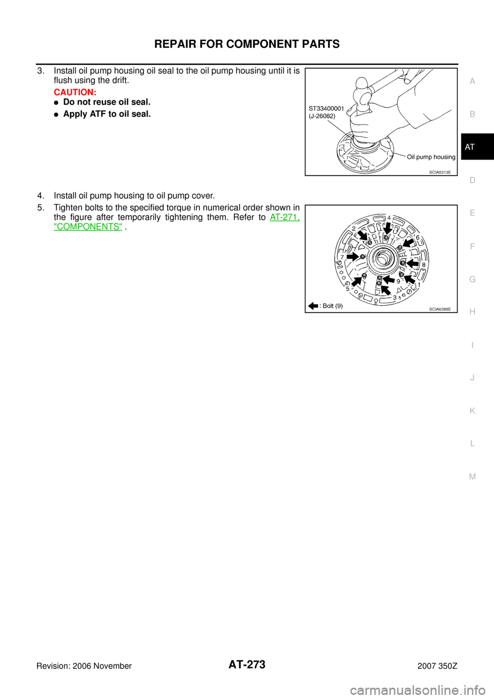
3. Install oil pump housing oil seal to the oil pump housing until it is
flush using the drift.
CAUTION:
�Do not reuse oil seal.
�Apply ATF to oil seal.
4. Install oil pump housing to oil pump cover.
5. Tighten bolts to the specified torque in numerical order shown in
the figure after temporarily tightening them. Refer to AT- 2 7 1 ,
"COMPONENTS" .
SCIA5313E
SCIA6388E
Page 274 of 312
AT-274
REPAIR FOR COMPONENT PARTS
Revision: 2006 November2007 350Z
Front Sun Gear, 3rd One-way ClutchNCS0009D
COMPONENTS
DISASSEMBLY
1. Remove snap ring from front sun gear using a flat-bladed screw-
driver.
2. Remove 3rd one-way clutch from front sun gear.
1. Front sun gear 2. 3rd one-way clutch 3. Snap ring
SCIA3114E
SCIA3110E
S C I A 3 111 E
Page 275 of 312
REPAIR FOR COMPONENT PARTS
AT-275
D
E
F
G
H
I
J
K
L
MA
B
AT
Revision: 2006 November2007 350Z
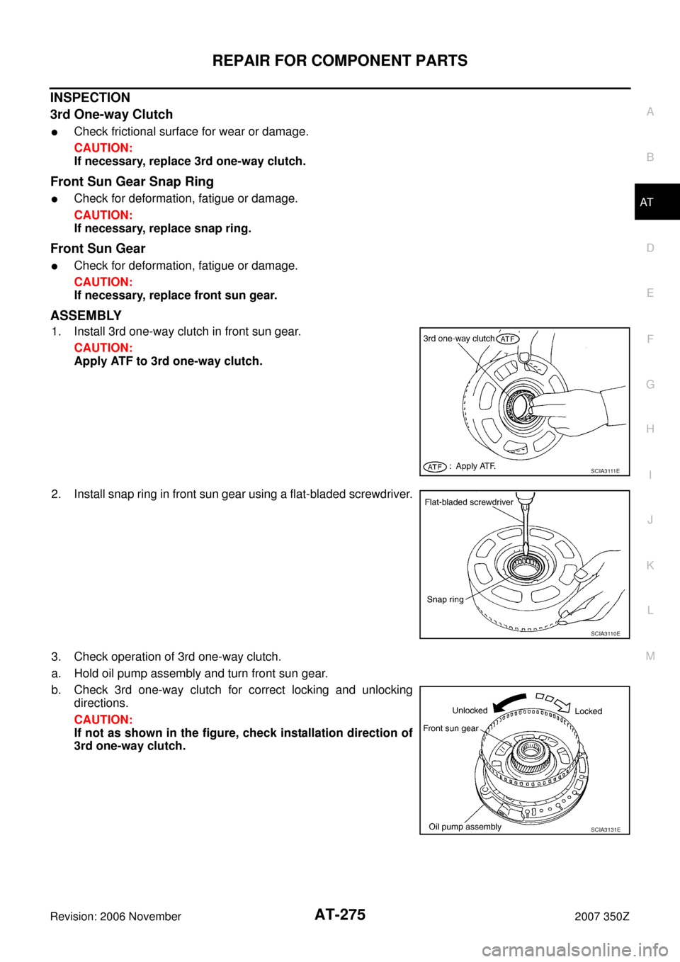
INSPECTION
3rd One-way Clutch
�Check frictional surface for wear or damage.
CAUTION:
If necessary, replace 3rd one-way clutch.
Front Sun Gear Snap Ring
�Check for deformation, fatigue or damage.
CAUTION:
If necessary, replace snap ring.
Front Sun Gear
�Check for deformation, fatigue or damage.
CAUTION:
If necessary, replace front sun gear.
ASSEMBLY
1. Install 3rd one-way clutch in front sun gear.
CAUTION:
Apply ATF to 3rd one-way clutch.
2. Install snap ring in front sun gear using a flat-bladed screwdriver.
3. Check operation of 3rd one-way clutch.
a. Hold oil pump assembly and turn front sun gear.
b. Check 3rd one-way clutch for correct locking and unlocking
directions.
CAUTION:
If not as shown in the figure, check installation direction of
3rd one-way clutch.
S C I A 3 111 E
SCIA3110E
SCIA3131E
Page 276 of 312
AT-276
REPAIR FOR COMPONENT PARTS
Revision: 2006 November2007 350Z
Front Carrier, Input Clutch, Rear Internal GearNCS0009E
COMPONENTS
1. Seal ring 2. O-ring 3. Needle bearing
4. Bearing race 5. Front carrier assembly 6. Needle bearing
7. Snap ring 8. Snap ring 9. Retaining plate
10. Driven plate 11. Input clutch drum 12. Drive plate
13. Rear internal gear
Refer to GI section to make sure icons (symbol marks) in the figure. Refer to GI-11, "
Components" .
SCIA6734E
Page 277 of 312
REPAIR FOR COMPONENT PARTS
AT-277
D
E
F
G
H
I
J
K
L
MA
B
AT
Revision: 2006 November2007 350Z
DISASSEMBLY
1. Compress snap ring using 2 flat-bladed screwdrivers.
2. Remove front carrier assembly and input clutch assembly from
rear internal gear.
3. Remove front carrier assembly from input clutch assembly.
a. Remove bearing race from front carrier assembly.
b. Remove needle bearing from front carrier assembly.
c. Remove snap ring from front carrier assembly.
CAUTION:
Do not expand snap ring excessively.
SCIA7475E
SCIA2847E
SCIA5233E
SCIA5476E
Page 278 of 312
AT-278
REPAIR FOR COMPONENT PARTS
Revision: 2006 November2007 350Z
4. Disassemble input clutch assembly.
a. Remove O-ring and seal rings from input clutch assembly.
b. Remove needle bearing from input clutch assembly.
c. Remove snap ring from input clutch drum using a flat-bladed
screwdriver.
d. Remove retaining plate, drive plates and driven plates from input
clutch drum.
INSPECTION
Front Carrier Snap Ring
�Check for deformation, fatigue or damage.
CAUTION:
If necessary, replace snap ring.
Input Clutch Snap Ring
�Check for deformation, fatigue or damage.
CAUTION:
If necessary, replace input clutch assembly.
Input Clutch Drum
�Check for deformation, fatigue or damage or burns.
CAUTION:
If necessary, replace input clutch assembly.
Input Clutch Drive Plates
�Check facing for burns, cracks or damage.
CAUTION:
If necessary, replace input clutch assembly.
Input Clutch Retaining Plate and Driven Plates
�Check facing for burns, cracks or damage.
SCIA5235E
SCIA2853E
SCIA2864E
Page 279 of 312

REPAIR FOR COMPONENT PARTS
AT-279
D
E
F
G
H
I
J
K
L
MA
B
AT
Revision: 2006 November2007 350Z
CAUTION:
If necessary, replace input clutch assembly.
Front Carrier
�Check for deformation, fatigue or damage.
CAUTION:
If necessary, replace front carrier assembly.
Rear Internal Gear
�Check for deformation, fatigue or damage.
CAUTION:
If necessary, replace rear internal gear.
ASSEMBLY
1. Install input clutch.
a. Install driven plates, drive plates and retaining plate in input
clutch drum.
�Snap ring (1)
�Retaining plate (2)
�Drive plate (3)
�Driven plate (4)
�Drive plate/Driven plate: 7/7
CAUTION:
Take care with order of plates.
b. Install snap ring in input clutch drum using a flat-bladed screw-
driver.
c. Install needle bearing in input clutch assembly.
CAUTION:
�Take care with the direction of needle bearing. Refer to
AT- 2 5 3 , "
Locations of Adjusting Shims, Needle Bearings,
Thrust Washers and Snap Rings" .
�Apply petroleum jelly to needle bearing.
SCIA7133E
SCIA2864E
SCIA2853E
Page 280 of 312
AT-280
REPAIR FOR COMPONENT PARTS
Revision: 2006 November2007 350Z
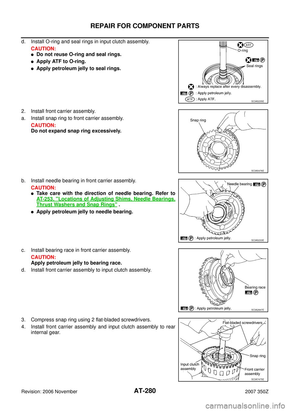
d. Install O-ring and seal rings in input clutch assembly.
CAUTION:
�Do not reuse O-ring and seal rings.
�Apply ATF to O-ring.
�Apply petroleum jelly to seal rings.
2. Install front carrier assembly.
a. Install snap ring to front carrier assembly.
CAUTION:
Do not expand snap ring excessively.
b. Install needle bearing in front carrier assembly.
CAUTION:
�Take care with the direction of needle bearing. Refer to
AT- 2 5 3 , "
Locations of Adjusting Shims, Needle Bearings,
Thrust Washers and Snap Rings" .
�Apply petroleum jelly to needle bearing.
c. Install bearing race in front carrier assembly.
CAUTION:
Apply petroleum jelly to bearing race.
d. Install front carrier assembly to input clutch assembly.
3. Compress snap ring using 2 flat-bladed screwdrivers.
4. Install front carrier assembly and input clutch assembly to rear
internal gear.
SCIA5235E
SCIA5476E
SCIA5233E
SCIA2847E
SCIA7475E
Trending: Turbine revolution sensor, diagnostic menu, oil change, set clock, air condition, brake fluid, fuel pressure