NISSAN ALMERA 2001 Service Manual
Manufacturer: NISSAN, Model Year: 2001, Model line: ALMERA, Model: NISSAN ALMERA 2001Pages: 2898, PDF Size: 60.76 MB
Page 1191 of 2898
6 CHECK GROUND CIRCUIT
1. Check harness continuity between heated oxygen sensor 2 (rear) harness connector terminal 4 and body ground.
Refer to wiring diagram.
Continuity should exist.
2. Also check harness for short to ground and short to power.
OK or NG
OK©GO TO 7.
NG©Repair open circuit or short to ground or short to power in harness or connectors.
7 CHECK HEATED OXYGEN SENSOR 2 (REAR)
Refer to ªComponent Inspectionº, EC-467.
OK or NG
OK©GO TO 8.
NG©Replace heated oxygen sensor 2 (rear).
8 CHECK INTERMITTENT INCIDENT
Perform ªTROUBLE DIAGNOSIS FOR INTERMITTENT INCIDENTº, EC-177.
©INSPECTION END
SEF662Y
Component InspectionNJEC1239HEATED OXYGEN SENSOR 2 (REAR)NJEC1239S01With CONSULT-II
1) Start engine and drive vehicle at a speed of more than 70 km/h
(43 MPH) for 2 consecutive minutes.
2) Stop vehicle with engine running.
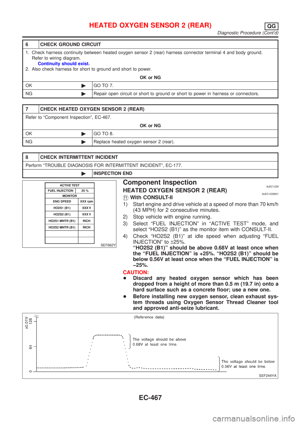
3) Select ªFUEL INJECTIONº in ªACTIVE TESTº mode, and
select ªHO2S2 (B1)º as the monitor item with CONSULT-II.
4) Check ªHO2S2 (B1)º at idle speed when adjusting ªFUEL
INJECTIONº to±25%.
ªHO2S2 (B1)º should be above 0.68V at least once when
the ªFUEL INJECTIONº is +25%. ªHO2S2 (B1)º should be
below 0.56V at least once when the ªFUEL INJECTIONº is
þ25%.
CAUTION:
+Discard any heated oxygen sensor which has been
dropped from a height of more than 0.5 m (19.7 in) onto a
hard surface such as a concrete floor; use a new one.
+Before installing new oxygen sensor, clean exhaust sys-
tem threads using Oxygen Sensor Thread Cleaner tool
and approved anti-seize lubricant.
SEF244YA
HEATED OXYGEN SENSOR 2 (REAR)QG
Diagnostic Procedure (Cont'd)
EC-467
Page 1192 of 2898
SEF032X
Without CONSULT-II
1) Start engine and drive vehicle at a speed of more than 70 km/h
(43 MPH) for 2 consecutive minutes.
2) Stop vehicle with engine running.
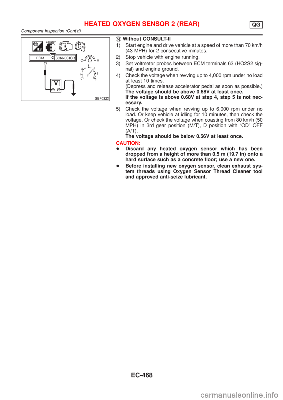
3) Set voltmeter probes between ECM terminals 63 (HO2S2 sig-
nal) and engine ground.
4) Check the voltage when revving up to 4,000 rpm under no load
at least 10 times.
(Depress and release accelerator pedal as soon as possible.)
The voltage should be above 0.68V at least once.
If the voltage is above 0.68V at step 4, step 5 is not nec-
essary.
5) Check the voltage when revving up to 6,000 rpm under no
load. Or keep vehicle at idling for 10 minutes, then check the
voltage. Or check the voltage when coasting from 80 km/h (50
MPH) in 3rd gear position (M/T), D position with ªODº OFF
(A/T).
The voltage should be below 0.56V at least once.
CAUTION:
+Discard any heated oxygen sensor which has been
dropped from a height of more than 0.5 m (19.7 in) onto a
hard surface such as a concrete floor; use a new one.
+Before installing new oxygen sensor, clean exhaust sys-
tem threads using Oxygen Sensor Thread Cleaner tool
and approved anti-seize lubricant.
HEATED OXYGEN SENSOR 2 (REAR)QG
Component Inspection (Cont'd)
EC-468
Page 1193 of 2898
DescriptionNJEC1240SYSTEM DESCRIPTIONNJEC1240S01
Sensor Input Signal to ECMECM func-
tionActuator
Camshaft position sensor (PHASE)
Crankshaft position sensor (POS)Engine speedHeated
oxygen
sensor 2
heater
(rear) con-
trolHeated oxygen sensor 2 heater
(rear)
The ECM performs ON/OFF control of the heated oxygen sensor 2 heater (rear) corresponding to the engine
speed.
OPERATIONNJEC1240S02
Engine condition Heated oxygen sensor 2 heater (rear)
Engine stopped OFF
Engine is running. After driving for 2 minutes at a speed
of 70 km/h (43 MPH) or moreON
Engine speed above 3,600 rpm OFF
CONSULT-II Reference Value in Data Monitor
Mode
NJEC1241Specification data are reference values.
MONITOR ITEM CONDITION SPECIFICATION
HO2S2 HTR (B1)+Engine speedBelow 3,600 rpm [After driving for 2 minutes at a
speed of 70 km/h (43 MPH) or more]ON
Above 3,600 rpm OFF
+Ignition switch ON (Engine stopped) OFF
ECM Terminals and Reference ValueNJEC1242Specification data are reference values and are measured between each terminal and ground.
CAUTION:
Do not use ECM ground terminals when measuring input/output voltage. Doing so may result in dam-
age to the ECM's transistor. Use a ground other than ECM terminals, such as the ground.
TERMI-
NAL
NO.WIRE
COLORITEM CONDITION DATA (DC Voltage)
3 W/RHeated oxygen sensor 2
heater (rear)[Engine is running]
+Engine speed is below 3,600 rpm [After driving
for 2 minutes at a speed of 70 km/h (43 MPH) or
more]0-1V
[Engine is running]
+Engine speed is above 3,600 rpm
BATTERY VOLTAGE
(11 - 14V)
[Ignition switch ªONº]
+Engine stopped
HEATED OXYGEN SENSOR 2 HEATER (REAR)QG
Description
EC-469
Page 1194 of 2898
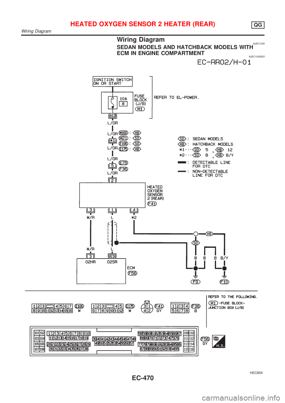
Wiring DiagramNJEC1245SEDAN MODELS AND HATCHBACK MODELS WITH
ECM IN ENGINE COMPARTMENT
NJEC1245S03
HEC854
HEATED OXYGEN SENSOR 2 HEATER (REAR)QG
Wiring Diagram
EC-470
Page 1195 of 2898
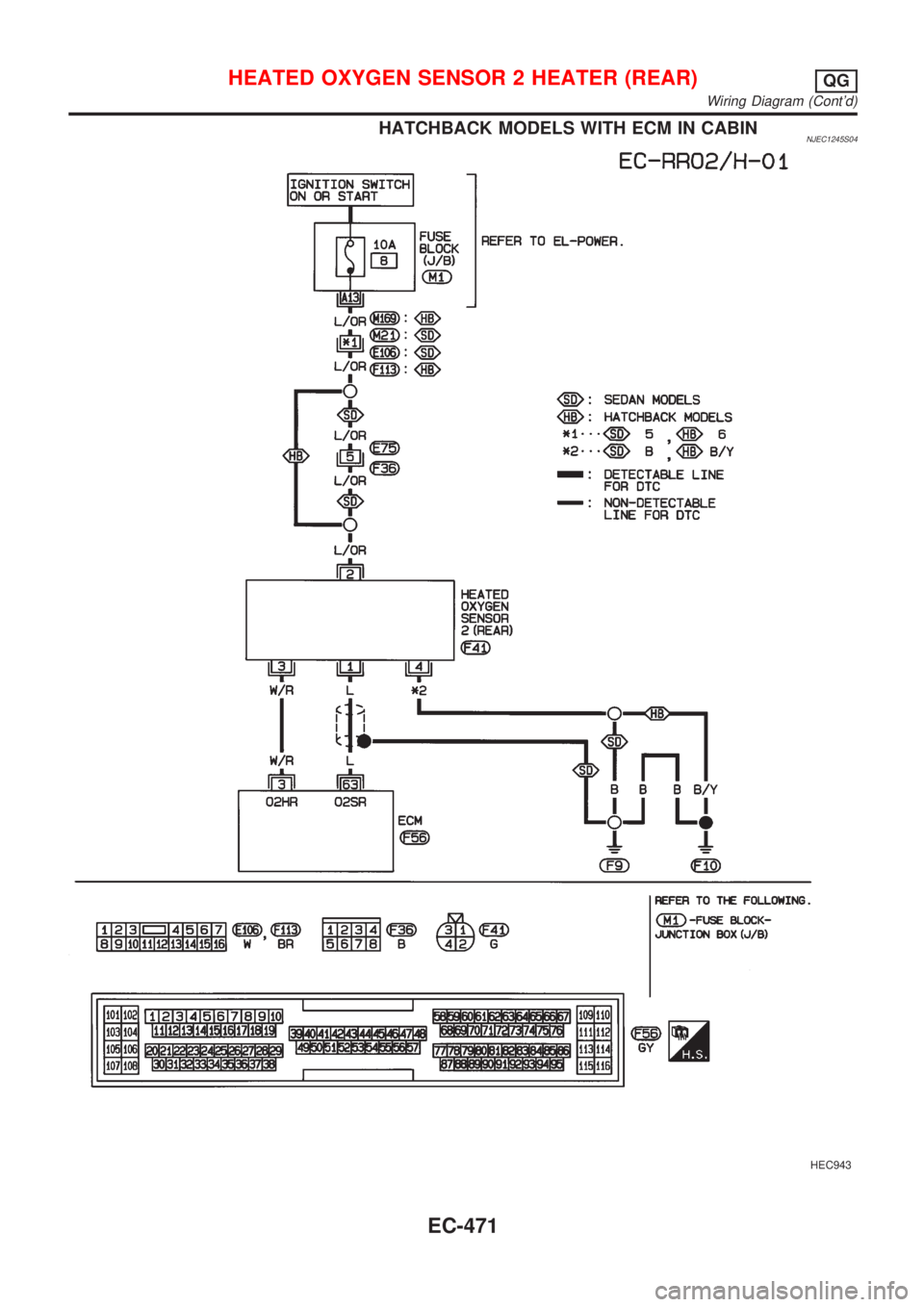
HATCHBACK MODELS WITH ECM IN CABINNJEC1245S04
HEC943
HEATED OXYGEN SENSOR 2 HEATER (REAR)QG
Wiring Diagram (Cont'd)
EC-471
Page 1196 of 2898
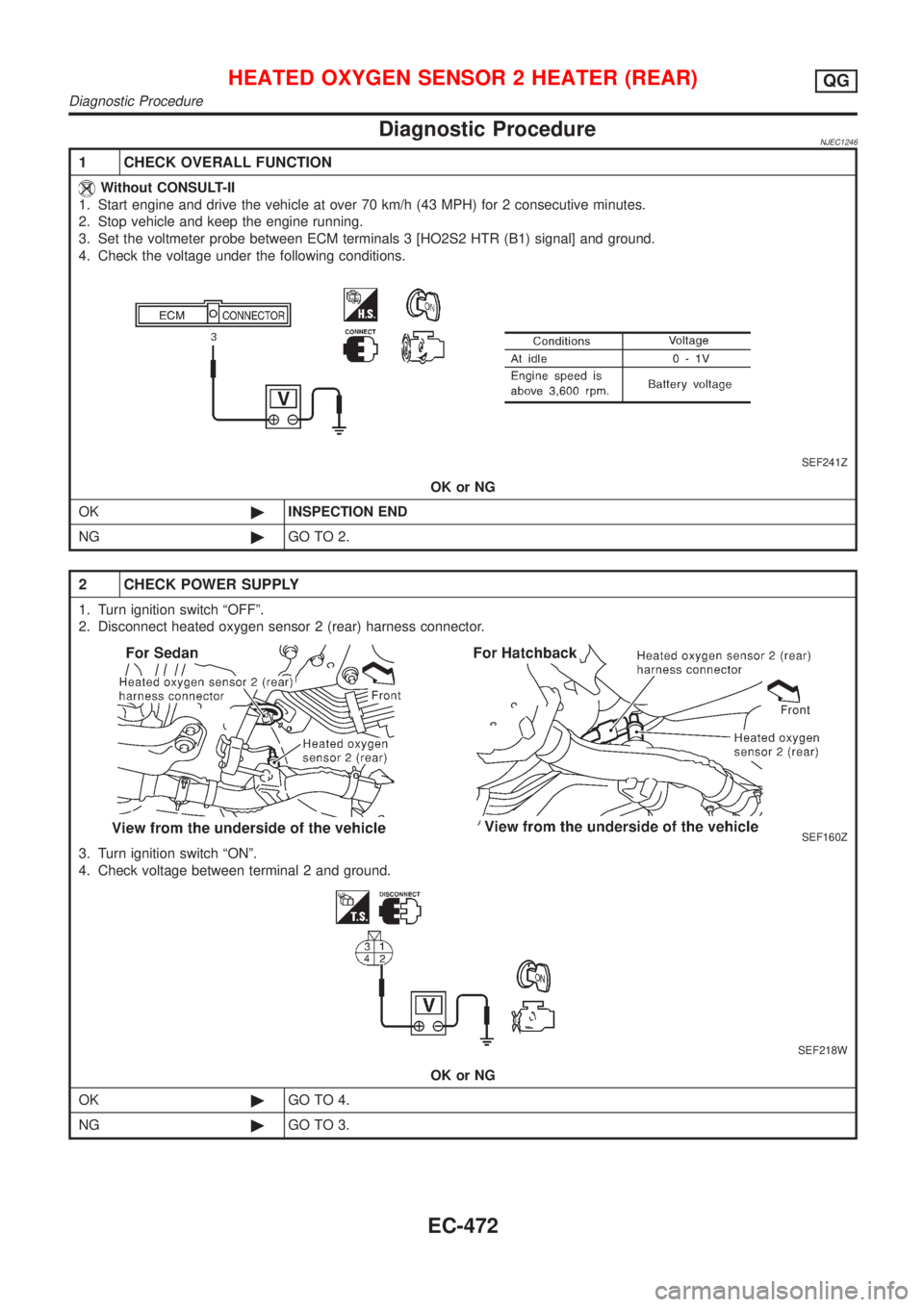
Diagnostic ProcedureNJEC1246
1 CHECK OVERALL FUNCTION
Without CONSULT-II
1. Start engine and drive the vehicle at over 70 km/h (43 MPH) for 2 consecutive minutes.
2. Stop vehicle and keep the engine running.
3. Set the voltmeter probe between ECM terminals 3 [HO2S2 HTR (B1) signal] and ground.
4. Check the voltage under the following conditions.
SEF241Z
OK or NG
OK©INSPECTION END
NG©GO TO 2.
2 CHECK POWER SUPPLY
1. Turn ignition switch ªOFFº.
2. Disconnect heated oxygen sensor 2 (rear) harness connector.
SEF160Z
3. Turn ignition switch ªONº.
4. Check voltage between terminal 2 and ground.
SEF218W
OK or NG
OK©GO TO 4.
NG©GO TO 3.
HEATED OXYGEN SENSOR 2 HEATER (REAR)QG
Diagnostic Procedure
EC-472
Page 1197 of 2898
3 DETECT MALFUNCTIONING PART
Check the following.
+Harness connectors E75, F36
+Harness connectors M21, E106 (Sedan), M160, E175 (Hatchback)
+Harness for open or short between heated oxygen sensor 2 (rear) and fuse
+10A fuse
©Repair harness or connectors.
4 CHECK GROUND CIRCUIT
1. Turn ignition switch ªOFFº.
2. Disconnect ECM harness connector.
3. Check harness continuity between heated oxygen sensor 2 (rear) harness connector terminal 3 and ECM terminal 3.
Refer to wiring diagram.
Continuity should exist.
4. Also check harness for short to ground and short to power.
OK or NG
OK©GO TO 6.
NG©GO TO 5.
5 DETECT MALFUNCTIONING PART
Check the harness for open or short between heated oxygen sensor 2 heater (rear) and ECM.
©Repair open circuit or short to ground or short to power in harness or connectors.
6 CHECK HEATED OXYGEN SENSOR 2 HEATER (REAR)
Refer to ªComponent Inspectionº, EC-474.
OK or NG
OK©GO TO 7.
NG©Replace heated oxygen sensor 2 (rear).
7 CHECK INTERMITTENT INCIDENT
Perform ªTROUBLE DIAGNOSIS FOR INTERMITTENT INCIDENTº, EC-177.
©INSPECTION END
HEATED OXYGEN SENSOR 2 HEATER (REAR)QG
Diagnostic Procedure (Cont'd)
EC-473
Page 1198 of 2898
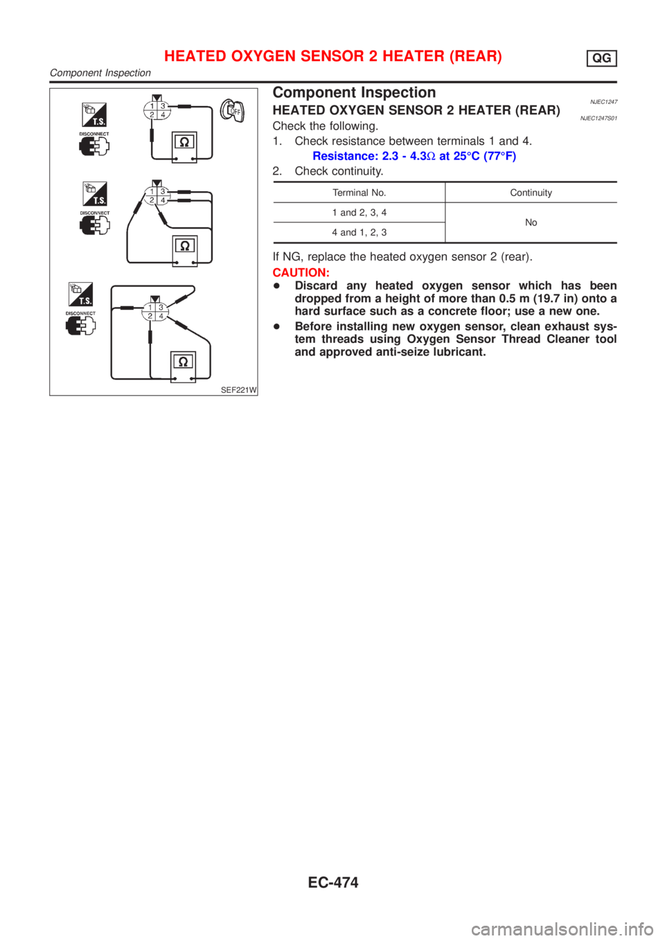
SEF221W
Component InspectionNJEC1247HEATED OXYGEN SENSOR 2 HEATER (REAR)NJEC1247S01Check the following.
1. Check resistance between terminals 1 and 4.
Resistance: 2.3 - 4.3Wat 25ÉC (77ÉF)
2. Check continuity.
Terminal No. Continuity
1 and 2, 3, 4
No
4 and 1, 2, 3
If NG, replace the heated oxygen sensor 2 (rear).
CAUTION:
+Discard any heated oxygen sensor which has been
dropped from a height of more than 0.5 m (19.7 in) onto a
hard surface such as a concrete floor; use a new one.
+Before installing new oxygen sensor, clean exhaust sys-
tem threads using Oxygen Sensor Thread Cleaner tool
and approved anti-seize lubricant.
HEATED OXYGEN SENSOR 2 HEATER (REAR)QG
Component Inspection
EC-474
Page 1199 of 2898
DescriptionNJEC1248SYSTEM DESCRIPTIONNJEC1248S01
Sensor Input Signal to ECMECM func-
tionActuator
Throttle position sensor Throttle position
Swirl con-
trol valve
system
controlSwirl control valve control sole-
noid valve via swirl control
valve Ignition switch Start signal
Crankshaft position sensor (POS) Engine speed
Camshaft position sensor (PHASE) Engine speed and cylinder number
Mass air flow sensor Amount of intake air
Engine coolant temperature sensor Engine coolant temperature
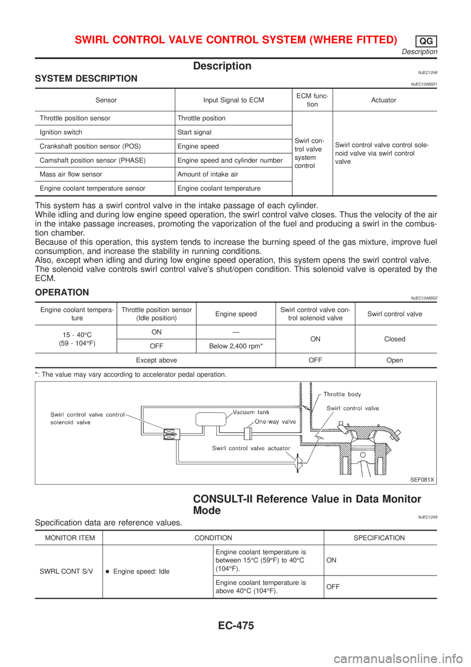
This system has a swirl control valve in the intake passage of each cylinder.
While idling and during low engine speed operation, the swirl control valve closes. Thus the velocity of the air
in the intake passage increases, promoting the vaporization of the fuel and producing a swirl in the combus-
tion chamber.
Because of this operation, this system tends to increase the burning speed of the gas mixture, improve fuel
consumption, and increase the stability in running conditions.
Also, except when idling and during low engine speed operation, this system opens the swirl control valve.
The solenoid valve controls swirl control valve's shut/open condition. This solenoid valve is operated by the
ECM.
OPERATIONNJEC1248S02
Engine coolant tempera-
tureThrottle position sensor
(Idle position)Engine speedSwirl control valve con-
trol solenoid valveSwirl control valve
15 - 40ÉC
(59 - 104ÉF)ON Ð
ON Closed
OFF Below 2,400 rpm*
Except above OFF Open
*: The value may vary according to accelerator pedal operation.
SEF081X
CONSULT-II Reference Value in Data Monitor
Mode
NJEC1249Specification data are reference values.
MONITOR ITEM CONDITION SPECIFICATION
SWRL CONT S/V+Engine speed: IdleEngine coolant temperature is
between 15ÉC (59ÉF) to 40ÉC
(104ÉF).ON
Engine coolant temperature is
above 40ÉC (104ÉF).OFF
SWIRL CONTROL VALVE CONTROL SYSTEM (WHERE FITTED)QG
Description
EC-475
Page 1200 of 2898
ECM Terminals and Reference Value=NJEC1250Specification data are reference values and are measured between each terminal and ground.
CAUTION:
Do not use ECM ground terminals when measuring input/output voltage. Doing so may result in dam-
age to the ECM's transistor. Use a ground other than ECM terminals, such as the ground.
TERMI-
NAL
NO.WIRE
COLORITEM CONDITION DATA (DC Voltage)
104 SBSwirl control valve control
solenoid valve[Engine is running]
+Engine coolant temperature is between 15ÉC
(59ÉF) to 40ÉC (104ÉF).
+Idle speed0-1V
[Engine is running]
+Engine coolant temperature is above 40ÉC
(104ÉF).
+Idle speedBATTERY VOLTAGE
(11 - 14V)
SEF098X
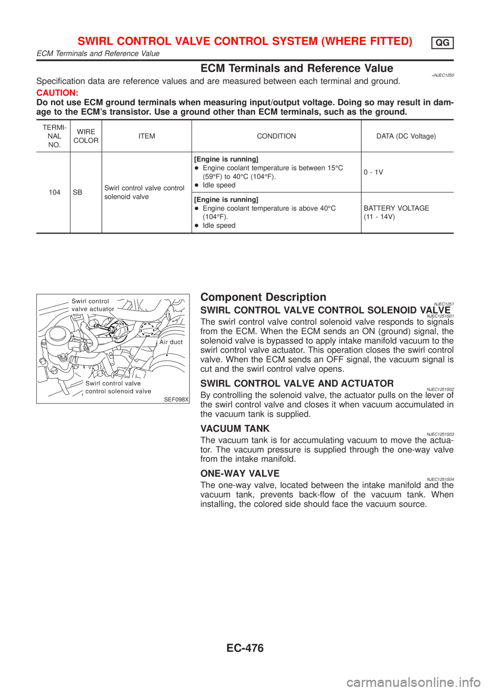
Component DescriptionNJEC1251SWIRL CONTROL VALVE CONTROL SOLENOID VALVENJEC1251S01The swirl control valve control solenoid valve responds to signals
from the ECM. When the ECM sends an ON (ground) signal, the
solenoid valve is bypassed to apply intake manifold vacuum to the
swirl control valve actuator. This operation closes the swirl control
valve. When the ECM sends an OFF signal, the vacuum signal is
cut and the swirl control valve opens.
SWIRL CONTROL VALVE AND ACTUATORNJEC1251S02By controlling the solenoid valve, the actuator pulls on the lever of
the swirl control valve and closes it when vacuum accumulated in
the vacuum tank is supplied.
VACUUM TANKNJEC1251S03The vacuum tank is for accumulating vacuum to move the actua-
tor. The vacuum pressure is supplied through the one-way valve
from the intake manifold.
ONE-WAY VALVENJEC1251S04The one-way valve, located between the intake manifold and the
vacuum tank, prevents back-flow of the vacuum tank. When
installing, the colored side should face the vacuum source.
SWIRL CONTROL VALVE CONTROL SYSTEM (WHERE FITTED)QG
ECM Terminals and Reference Value
EC-476