NISSAN ALMERA 2001 Service Manual
Manufacturer: NISSAN, Model Year: 2001, Model line: ALMERA, Model: NISSAN ALMERA 2001Pages: 2898, PDF Size: 60.76 MB
Page 1561 of 2898
Filament Repair .......................................................257
AUDIO..........................................................................258
System Description/Sedan ......................................258
Schematic/Sedan .....................................................260
Wiring Diagram - AUDIO -/Sedan ...........................261
System Description/Hatchback ................................269
Schematic/Hatchback ..............................................271
Wiring Diagram - AUDIO -/Hatchback .....................272
Trouble Diagnoses...................................................280
Inspection.................................................................281
AUDIO ANTENNA.......................................................282
Wiring Diagram - P/ANT - .......................................282
Location of Antenna/Power Antenna .......................283
Antenna Rod Replacement/Power Antenna ............284
Window Antenna Repair ..........................................284
Location of Antenna/Sedan With Manual Antenna..286
Antenna Rod Replacement/Sedan With Manual
Antenna....................................................................286
Location of Antenna/Hatchback ...............................287
Antenna Rod Replacement/Hatchback ...................287
HEATED SEAT............................................................288
Wiring Diagram - H/SEAT -/Sedan ..........................288
Wiring Diagram - H/SEAT -/Hatchback ...................290
POWER SUNROOF.....................................................292
Wiring Diagram - SROOF - .....................................292
Trouble Diagnoses...................................................293
DOOR MIRROR...........................................................294
Wiring Diagram - MIRROR -/Sedan ........................294
Wiring Diagram - MIRROR -/Hatchback .................295
TRUNK LID OPENER..................................................297
Wiring Diagram - TLID - ..........................................297
POWER WINDOW.......................................................298
System Description/Sedan ......................................298
Schematic/Sedan .....................................................300
Wiring Diagram - WINDOW -/Sedan .......................301
Trouble Diagnoses/Sedan .......................................305
System Description/Hatchback ................................306
Schematic/Hatchback ..............................................308
Wiring Diagram - WINDOW -/Hatchback ................309
Trouble Diagnoses/Hatchback.................................313
POWER DOOR LOCK.................................................314
System Description/Hatchback ................................314
Schematic/Hatchback ..............................................316
Wiring Diagram - D/LOCK -/Hatchback...................318
Trouble Diagnoses/Hatchback.................................325
System Description/Sedan ......................................333
Schematic/Sedan .....................................................334
Wiring Diagram - D/LOCK -/Sedan .........................335
Trouble Diagnoses/Sedan .......................................340
POWER DOOR LOCK - SUPER LOCK -...................349
System Description ..................................................349
Schematic/Sedan .....................................................351Wiring Diagram - S/LOCK -/Sedan .........................352
Trouble Diagnoses/Sedan .......................................358
Schematic/Hatchback ..............................................370
Wiring Diagram - S/LOCK -/Hatchback ...................372
Trouble Diagnoses/Hatchback.................................379
MULTI-REMOTE CONTROL SYSTEM.......................392
System Description/Sedan ......................................392
Wiring Diagram - MULTI -/Sedan ............................393
Trouble Diagnoses/Sedan .......................................395
ID Code Entry Procedure/Sedan .............................402
Remote Controller Battery Replacement/Sedan .....403
System Description/Hatchback ................................403
Wiring Diagram - MULTI -/Hatchback .....................405
Trouble Diagnoses/Hatchback.................................407
ID Code Entry Procedure/Hatchback ......................412
Remote Controller Battery
Replacement/Hatchback ..........................................413
TIME CONTROL UNIT................................................414
Description/Sedan....................................................414
Schematic/Sedan .....................................................415
Time Control Unit Inspection Table/Sedan ..............416
Description/Hatchback .............................................417
Trouble Diagnoses/Hatchback.................................418
Schematic/Hatchback ..............................................420
NATS (NISSAN ANTI-THEFT SYSTEM).....................422
Component Parts and Harness Connetor
Location ...................................................................422
System Description ..................................................423
System Composition ................................................424
Wiring Diagram - NATS -/Sedan .............................425
Wiring Diagram - NATS -/Hatchback.......................427
CONSULT-II .............................................................429
Trouble Diagnoses...................................................432
How to Replace NATS IMMU ..................................449
NAVIGATION SYSTEM...............................................450
Precautions ..............................................................450
Component Parts Location ......................................451
System Description ..................................................452
Schematic/Sedan .....................................................460
Wiring Diagram - NAVI -/Sedan ..............................461
Schematic/Hatchback ..............................................467
Wiring Diagram - NAVI -/Hatchback ........................468
Self-diagnosis Mode ................................................476
Confirmation/Adjustment Mode ...............................479
Control Panel Mode .................................................491
Guide Volume Setting ..............................................498
Anti-theft System .....................................................499
CONSULT-II .............................................................500
Trouble Diagnoses...................................................501
This Condition Is Not Abnormal...............................507
Program Loading .....................................................516
CONTENTS(Cont'd)
EL-3
Page 1562 of 2898
ELECTRICAL UNITS LOCATION...............................517
Engine Compartment ...............................................517
Passenger Compartment/LHD Models ....................518
Passenger Compartment/RHD Models ...................520
HARNESS LAYOUT....................................................522
How to Read Harness Layout .................................522
Outline/Sedan ..........................................................523
Outline/Hatchback....................................................525
Main Harness/Sedan ...............................................528
Main Harness/Hatchback.........................................532
Engine Room Harness/Sedan .................................536
Engine Room Harness/Hatchback ..........................542
Engine Control Harness/QG Engine Models...........546Engine Control Harness/YD Engine Models ...........550
Body Harness/Sedan ...............................................554
Body Harness/Hatchback ........................................562
Room Lamp Harness...............................................566
Front Door Harness/LHD Models ............................567
Front Door Harness/RHD Models ...........................569
Rear Door Harness..................................................571
Back Door Harness .................................................573
BULB SPECIFICATIONS............................................574
Headlamp.................................................................574
Exterior Lamp ..........................................................574
Interior Lamp............................................................574
WIRING DIAGRAM CODES (CELL CODES).............575
CONTENTS(Cont'd)
EL-4
Page 1563 of 2898
Supplemental Restraint System (SRS) ªAIR
BAGº and ªSEAT BELT PRE-TENSIONERº
NJEL0001The Supplemental Restraint System such as ªAIR BAGº and ªSEAT BELT PRE-TENSIONERº used along with
a seat belt, helps to reduce the risk or severity of injury to the driver and front passenger for certain types of
collision. The SRS system composition which is available to NISSAN MODEL N16 is as follows (The compo-
sition varies according to the destination and optional equipment.):
+For a frontal collision
The Supplemental Restraint System consists of driver air bag module (located in the center of the steer-
ing wheel), front passenger air bag module (located on the instrument panel on passenger side), front seat
belt pre-tensioners, a diagnosis sensor unit, warning lamp, wiring harness and spiral cable.
+For a side collision
The Supplemental Restraint System consists of front side air bag module (located in the outer side of front
seat), side air bag (satellite) sensor, diagnosis sensor unit (one of components of air bags for a frontal
collision), wiring harness, warning lamp (one of components of air bags for a frontal collision).
Information necessary to service the system safely is included in theRS sectionof this Service Manual.
WARNING:
+To avoid rendering the SRS inoperative, which could increase the risk of personal injury or death
in the event of a collision which would result in air bag inflation, all maintenance should be per-
formed by an authorized NISSAN dealer.
+Improper maintenance, including incorrect removal and installation of the SRS, can lead to per-
sonal injury caused by unintentional activation of the system. For removal of Spiral Cable and Air
Bag Module, see the RS section.
+Do not use electrical test equipment on any circuit related to the SRS unless instructed to in this
Service Manual. SRS wiring harnesses can be identified by yellow harness connector.
Wiring Diagrams and Trouble DiagnosisNJEL0002When you read wiring diagrams, refer to the following:
+Refer to GI-11, ªHOW TO READ WIRING DIAGRAMSº
+Refer to EL-10, ªPOWER SUPPLY ROUTINGº for power distribution circuit
When you perform trouble diagnosis, refer to the following:
+Refer to GI-32, ªHOW TO FOLLOW TEST GROUPS IN TROUBLE DIAGNOSESº
+Refer to GI-21, ªHOW TO PERFORM EFFICIENT DIAGNOSIS FOR AN ELECTRICAL INCIDENTº
Check for any Service bulletins before servicing the vehicle.
PRECAUTIONS
Supplemental Restraint System (SRS) ªAIR BAGº and ªSEAT BELT PRE-TENSIONERº
EL-5
Page 1564 of 2898
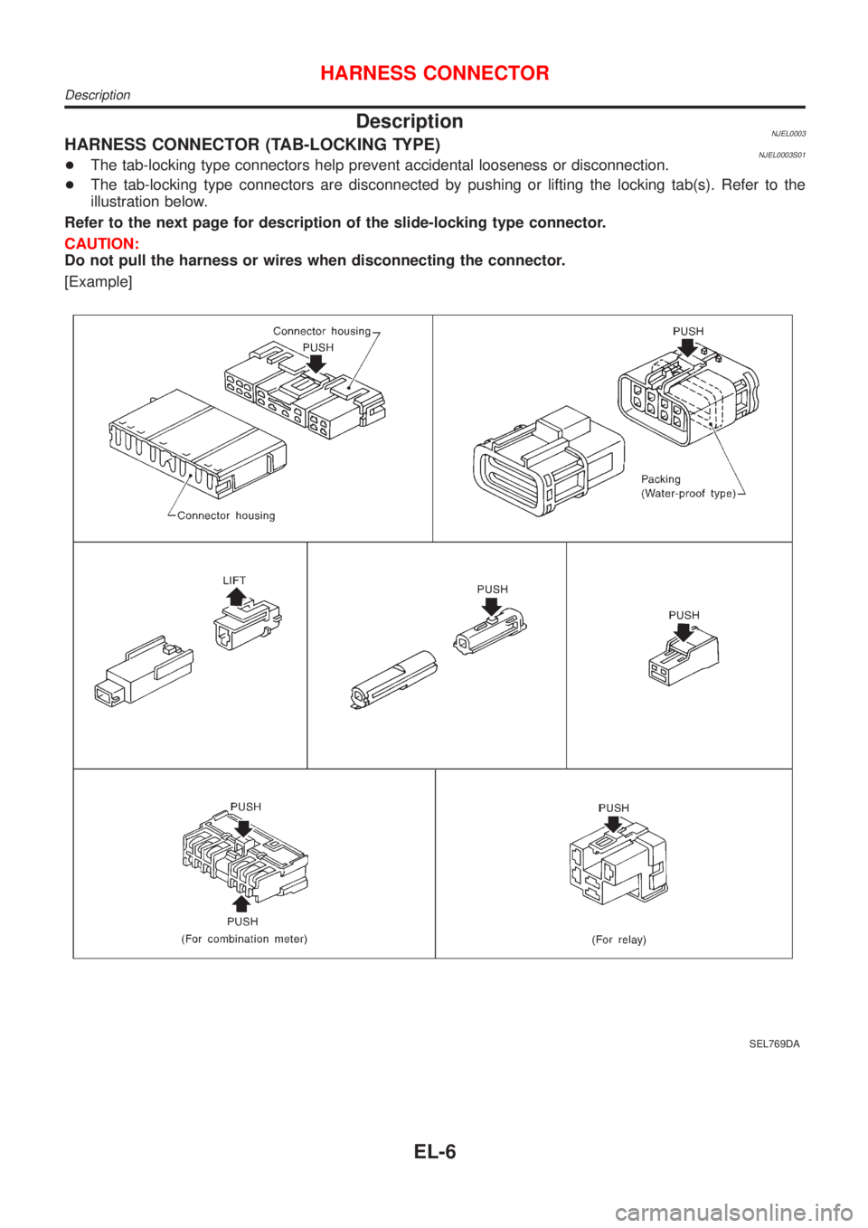
DescriptionNJEL0003HARNESS CONNECTOR (TAB-LOCKING TYPE)NJEL0003S01+The tab-locking type connectors help prevent accidental looseness or disconnection.
+The tab-locking type connectors are disconnected by pushing or lifting the locking tab(s). Refer to the
illustration below.
Refer to the next page for description of the slide-locking type connector.
CAUTION:
Do not pull the harness or wires when disconnecting the connector.
[Example]
SEL769DA
HARNESS CONNECTOR
Description
EL-6
Page 1565 of 2898
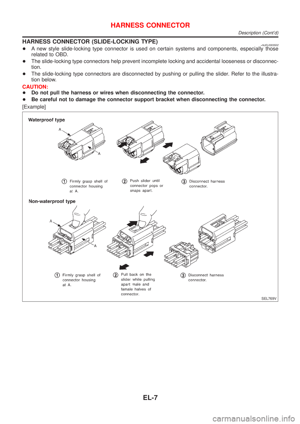
HARNESS CONNECTOR (SLIDE-LOCKING TYPE)=NJEL0003S02+A new style slide-locking type connector is used on certain systems and components, especially those
related to OBD.
+The slide-locking type connectors help prevent incomplete locking and accidental looseness or disconnec-
tion.
+The slide-locking type connectors are disconnected by pushing or pulling the slider. Refer to the illustra-
tion below.
CAUTION:
+Do not pull the harness or wires when disconnecting the connector.
+Be careful not to damage the connector support bracket when disconnecting the connector.
[Example]
SEL769V
HARNESS CONNECTOR
Description (Cont'd)
EL-7
Page 1566 of 2898
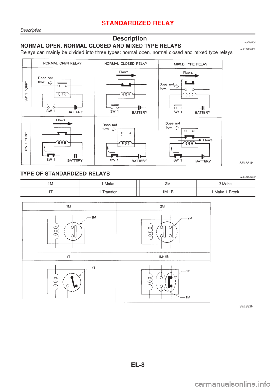
DescriptionNJEL0004NORMAL OPEN, NORMAL CLOSED AND MIXED TYPE RELAYSNJEL0004S01Relays can mainly be divided into three types: normal open, normal closed and mixed type relays.
SEL881H
TYPE OF STANDARDIZED RELAYSNJEL0004S02
1M 1 Make 2M 2 Make
1T 1 Transfer 1M´1B 1 Make 1 Break
SEL882H
STANDARDIZED RELAY
Description
EL-8
Page 1567 of 2898
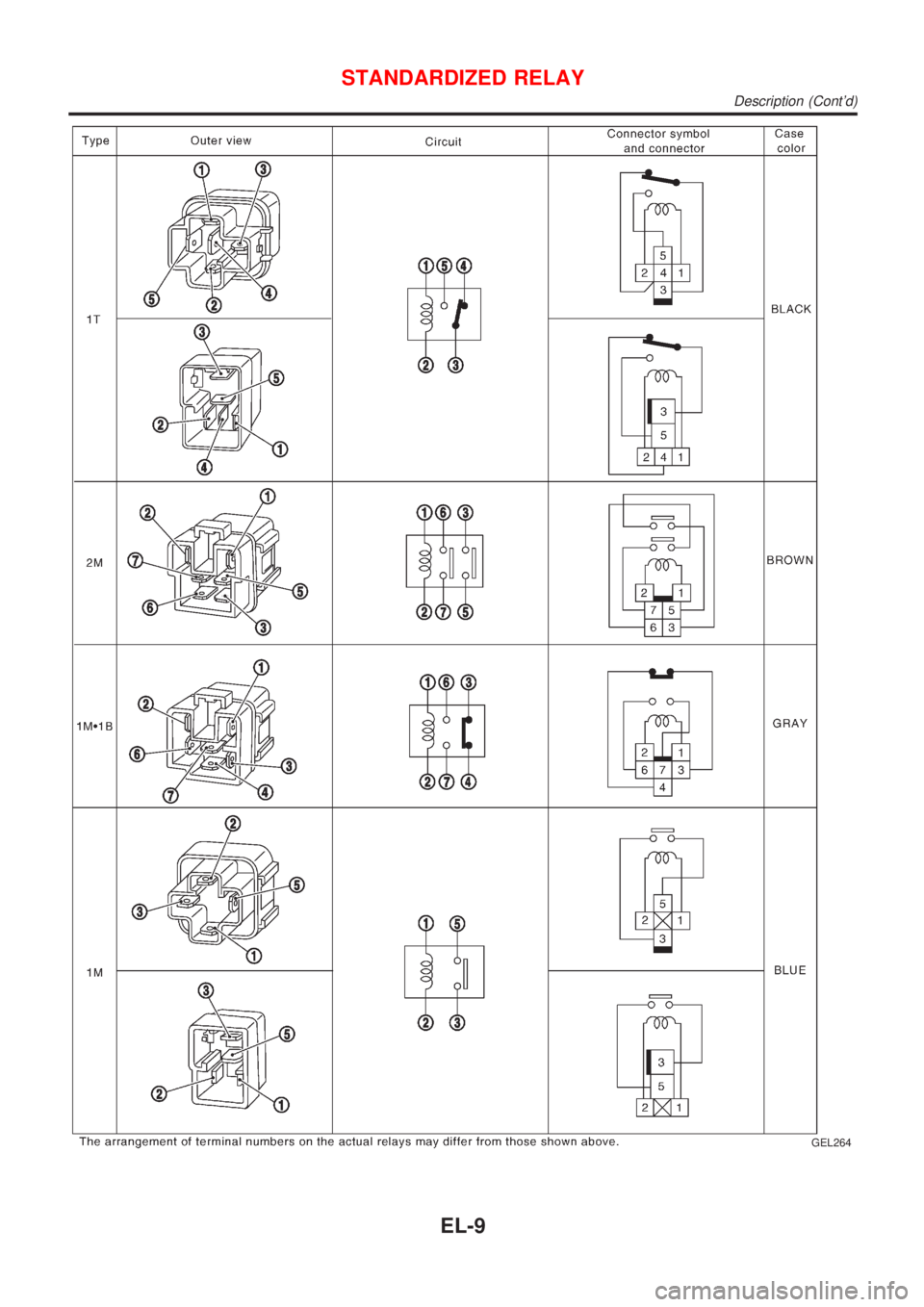
GEL264
STANDARDIZED RELAY
Description (Cont'd)
EL-9
Page 1568 of 2898
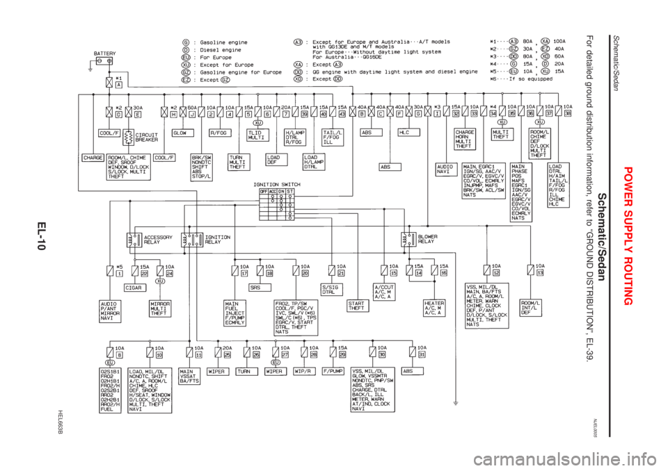
Schematic/SedanNJEL0005For detailed ground distribution information, refer to ªGROUND DISTRIBUTIONº, EL-39.
HEL663B
POWER SUPPLY ROUTING
Schematic/Sedan
EL-10
Page 1569 of 2898
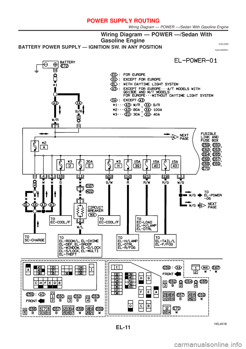
Wiring Diagram Ð POWER Ð/Sedan With
Gasoline Engine
NJEL0006BATTERY POWER SUPPLY Ð IGNITION SW. IN ANY POSITIONNJEL0006S01
HEL451B
POWER SUPPLY ROUTING
Wiring Diagram Ð POWER Ð/Sedan With Gasoline Engine
EL-11
Page 1570 of 2898

HEL352B
POWER SUPPLY ROUTING
Wiring Diagram Ð POWER Ð/Sedan With Gasoline Engine (Cont'd)
EL-12