NISSAN ALMERA 2001 Service Manual
ALMERA 2001
NISSAN
NISSAN
https://www.carmanualsonline.info/img/5/57348/w960_57348-0.png
NISSAN ALMERA 2001 Service Manual
Trending: tow, coolant, interior lights, open gas tank, mirror, tire type, Front brakes
Page 1541 of 2898
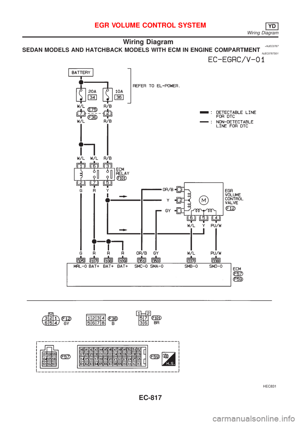
Wiring Diagram=NJEC0767SEDAN MODELS AND HATCHBACK MODELS WITH ECM IN ENGINE COMPARTMENTNJEC0767S01
HEC831
EGR VOLUME CONTROL SYSTEMYD
Wiring Diagram
EC-817
Page 1542 of 2898
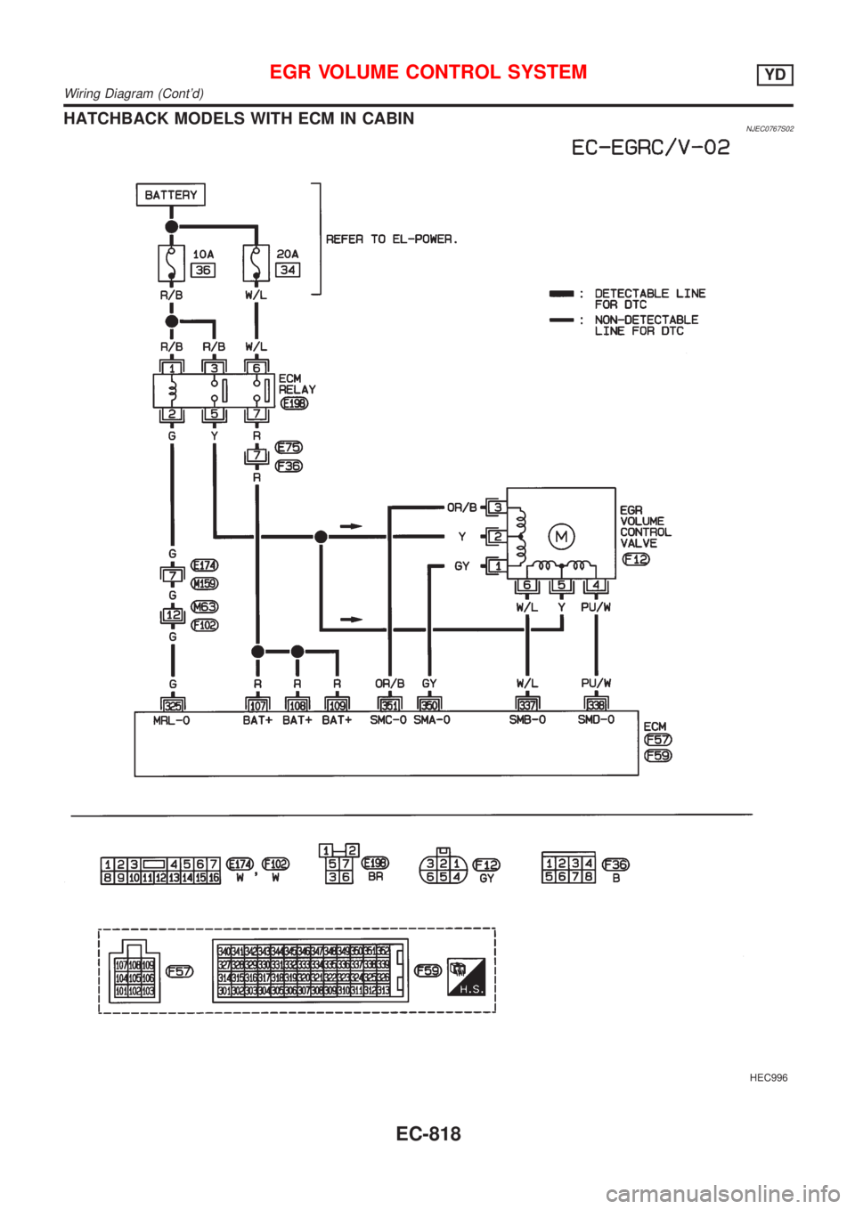
HATCHBACK MODELS WITH ECM IN CABINNJEC0767S02
HEC996
EGR VOLUME CONTROL SYSTEMYD
Wiring Diagram (Cont'd)
EC-818
Page 1543 of 2898
Diagnostic ProcedureNJEC0768
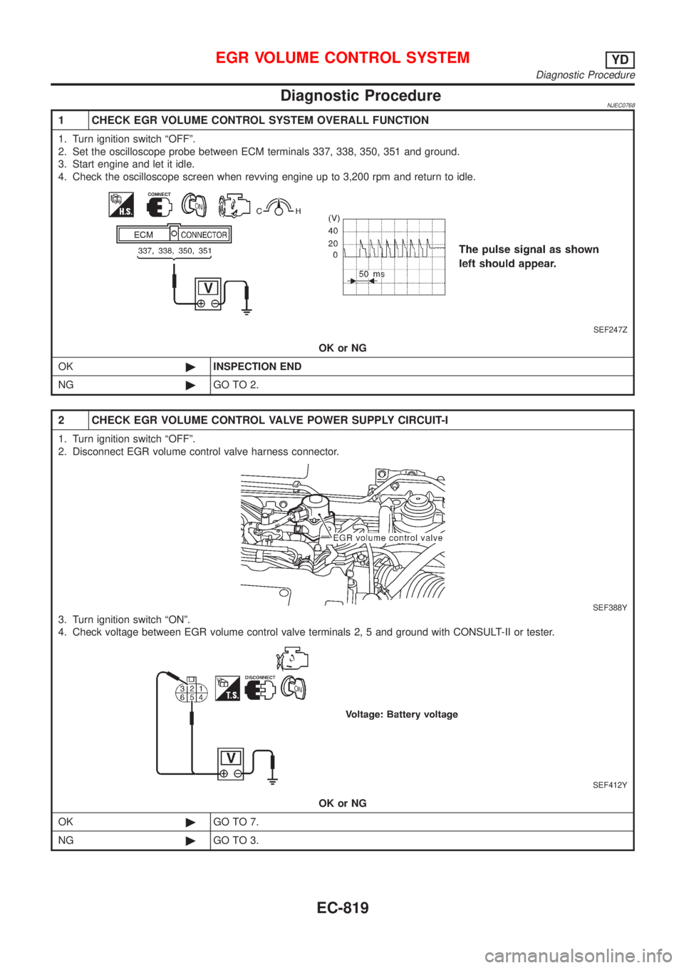
1 CHECK EGR VOLUME CONTROL SYSTEM OVERALL FUNCTION
1. Turn ignition switch ªOFFº.
2. Set the oscilloscope probe between ECM terminals 337, 338, 350, 351 and ground.
3. Start engine and let it idle.
4. Check the oscilloscope screen when revving engine up to 3,200 rpm and return to idle.
SEF247Z
OK or NG
OK©INSPECTION END
NG©GO TO 2.
2 CHECK EGR VOLUME CONTROL VALVE POWER SUPPLY CIRCUIT-I
1. Turn ignition switch ªOFFº.
2. Disconnect EGR volume control valve harness connector.
SEF388Y
3. Turn ignition switch ªONº.
4. Check voltage between EGR volume control valve terminals 2, 5 and ground with CONSULT-II or tester.
SEF412Y
OK or NG
OK©GO TO 7.
NG©GO TO 3.
EGR VOLUME CONTROL SYSTEMYD
Diagnostic Procedure
EC-819
Page 1544 of 2898
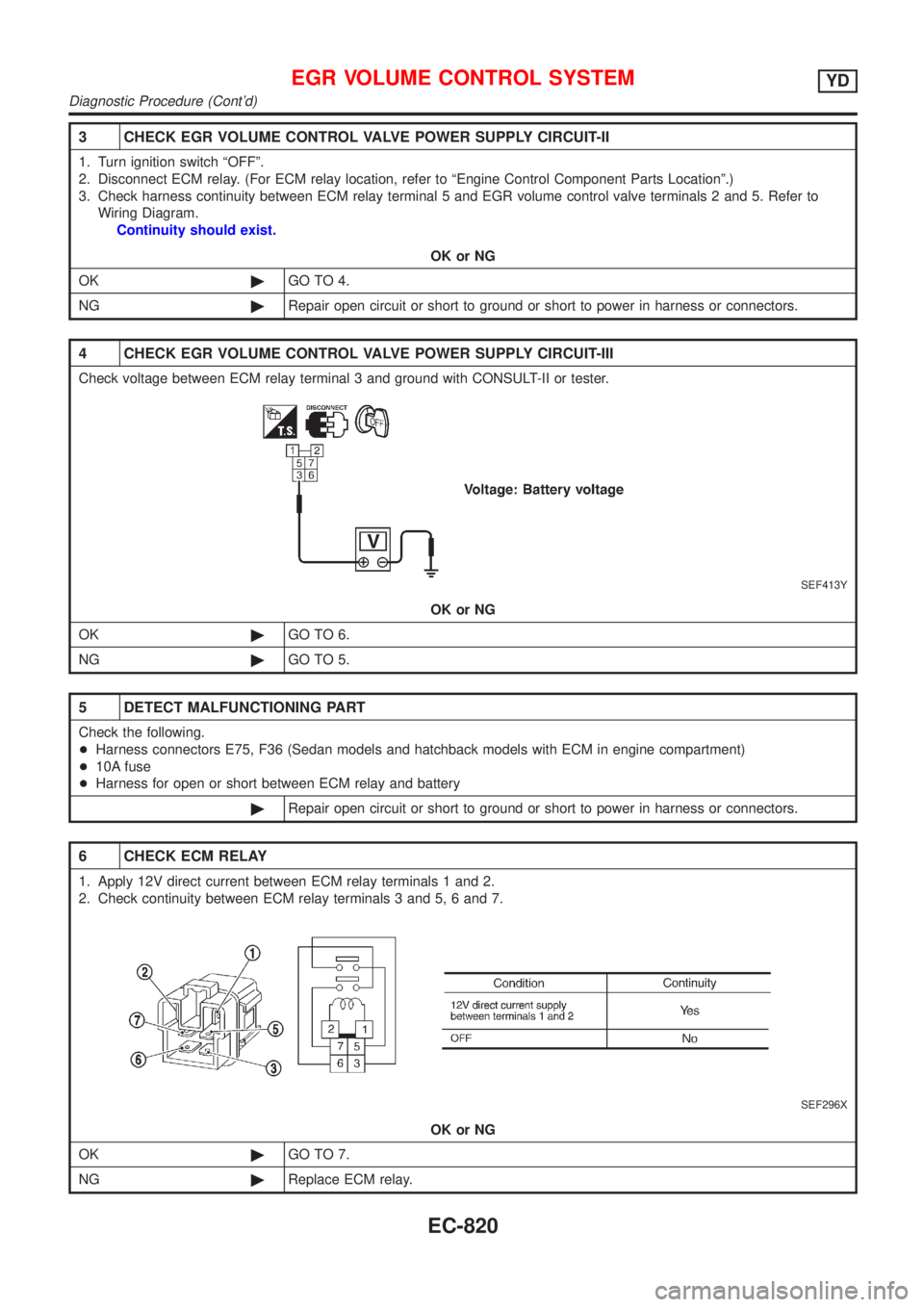
3 CHECK EGR VOLUME CONTROL VALVE POWER SUPPLY CIRCUIT-II
1. Turn ignition switch ªOFFº.
2. Disconnect ECM relay. (For ECM relay location, refer to ªEngine Control Component Parts Locationº.)
3. Check harness continuity between ECM relay terminal 5 and EGR volume control valve terminals 2 and 5. Refer to
Wiring Diagram.
Continuity should exist.
OK or NG
OK©GO TO 4.
NG©Repair open circuit or short to ground or short to power in harness or connectors.
4 CHECK EGR VOLUME CONTROL VALVE POWER SUPPLY CIRCUIT-III
Check voltage between ECM relay terminal 3 and ground with CONSULT-II or tester.
SEF413Y
OK or NG
OK©GO TO 6.
NG©GO TO 5.
5 DETECT MALFUNCTIONING PART
Check the following.
+Harness connectors E75, F36 (Sedan models and hatchback models with ECM in engine compartment)
+10A fuse
+Harness for open or short between ECM relay and battery
©Repair open circuit or short to ground or short to power in harness or connectors.
6 CHECK ECM RELAY
1. Apply 12V direct current between ECM relay terminals 1 and 2.
2. Check continuity between ECM relay terminals 3 and 5, 6 and 7.
SEF296X
OK or NG
OK©GO TO 7.
NG©Replace ECM relay.
EGR VOLUME CONTROL SYSTEMYD
Diagnostic Procedure (Cont'd)
EC-820
Page 1545 of 2898
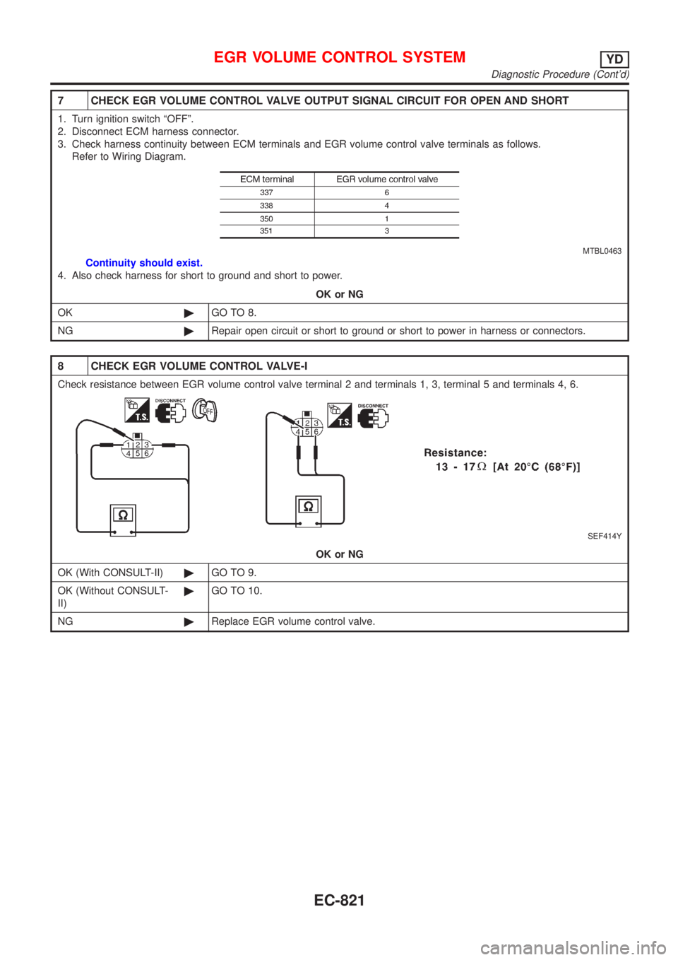
7 CHECK EGR VOLUME CONTROL VALVE OUTPUT SIGNAL CIRCUIT FOR OPEN AND SHORT
1. Turn ignition switch ªOFFº.
2. Disconnect ECM harness connector.
3. Check harness continuity between ECM terminals and EGR volume control valve terminals as follows.
Refer to Wiring Diagram.
MTBL0463
Continuity should exist.
4. Also check harness for short to ground and short to power.
OK or NG
OK©GO TO 8.
NG©Repair open circuit or short to ground or short to power in harness or connectors.
8 CHECK EGR VOLUME CONTROL VALVE-I
Check resistance between EGR volume control valve terminal 2 and terminals 1, 3, terminal 5 and terminals 4, 6.
SEF414Y
OK or NG
OK (With CONSULT-II)©GO TO 9.
OK (Without CONSULT-
II)©GO TO 10.
NG©Replace EGR volume control valve.
EGR VOLUME CONTROL SYSTEMYD
Diagnostic Procedure (Cont'd)
EC-821
Page 1546 of 2898
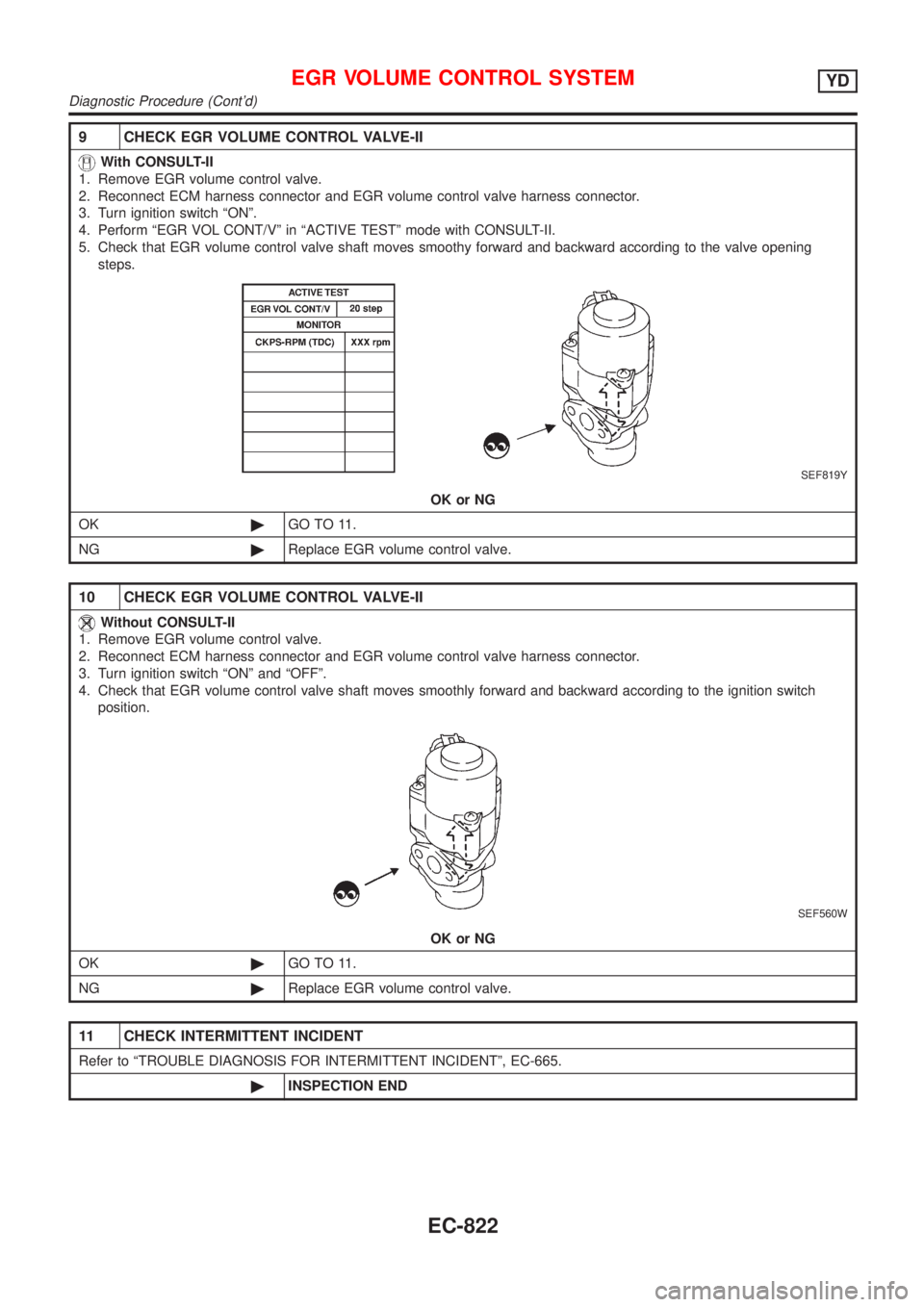
9 CHECK EGR VOLUME CONTROL VALVE-II
With CONSULT-II
1. Remove EGR volume control valve.
2. Reconnect ECM harness connector and EGR volume control valve harness connector.
3. Turn ignition switch ªONº.
4. Perform ªEGR VOL CONT/Vº in ªACTIVE TESTº mode with CONSULT-II.
5. Check that EGR volume control valve shaft moves smoothy forward and backward according to the valve opening
steps.
SEF819Y
OK or NG
OK©GO TO 11.
NG©Replace EGR volume control valve.
10 CHECK EGR VOLUME CONTROL VALVE-II
Without CONSULT-II
1. Remove EGR volume control valve.
2. Reconnect ECM harness connector and EGR volume control valve harness connector.
3. Turn ignition switch ªONº and ªOFFº.
4. Check that EGR volume control valve shaft moves smoothly forward and backward according to the ignition switch
position.
SEF560W
OK or NG
OK©GO TO 11.
NG©Replace EGR volume control valve.
11 CHECK INTERMITTENT INCIDENT
Refer to ªTROUBLE DIAGNOSIS FOR INTERMITTENT INCIDENTº, EC-665.
©INSPECTION END
EGR VOLUME CONTROL SYSTEMYD
Diagnostic Procedure (Cont'd)
EC-822
Page 1547 of 2898
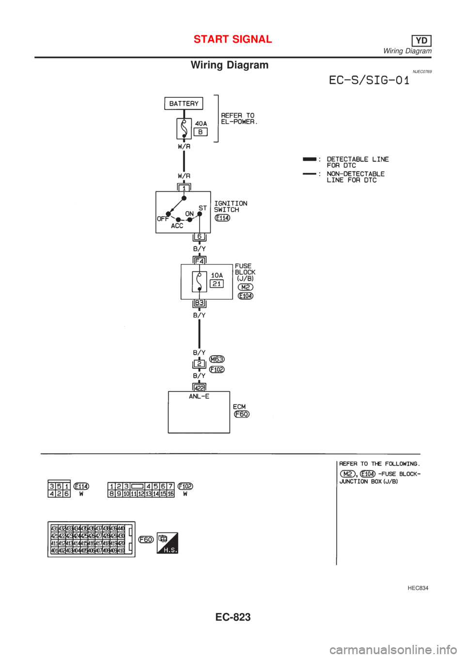
Wiring DiagramNJEC0769
HEC834
START SIGNALYD
Wiring Diagram
EC-823
Page 1548 of 2898
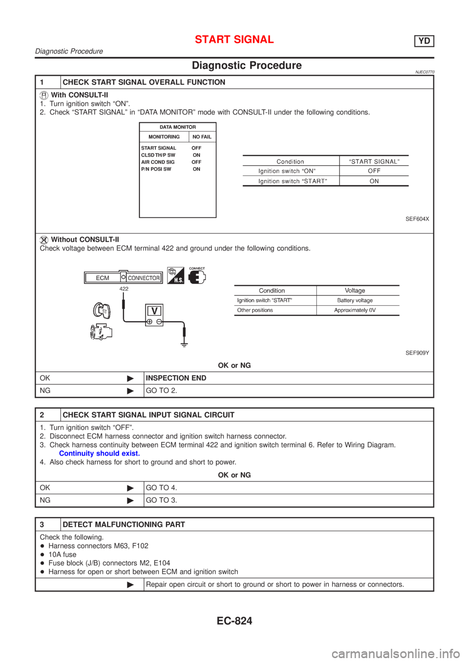
Diagnostic ProcedureNJEC0770
1 CHECK START SIGNAL OVERALL FUNCTION
With CONSULT-II
1. Turn ignition switch ªONº.
2. Check ªSTART SIGNALº in ªDATA MONITORº mode with CONSULT-II under the following conditions.
SEF604X
Without CONSULT-II
Check voltage between ECM terminal 422 and ground under the following conditions.
SEF909Y
OK or NG
OK©INSPECTION END
NG©GO TO 2.
2 CHECK START SIGNAL INPUT SIGNAL CIRCUIT
1. Turn ignition switch ªOFFº.
2. Disconnect ECM harness connector and ignition switch harness connector.
3. Check harness continuity between ECM terminal 422 and ignition switch terminal 6. Refer to Wiring Diagram.
Continuity should exist.
4. Also check harness for short to ground and short to power.
OK or NG
OK©GO TO 4.
NG©GO TO 3.
3 DETECT MALFUNCTIONING PART
Check the following.
+Harness connectors M63, F102
+10A fuse
+Fuse block (J/B) connectors M2, E104
+Harness for open or short between ECM and ignition switch
©Repair open circuit or short to ground or short to power in harness or connectors.
START SIGNALYD
Diagnostic Procedure
EC-824
Page 1549 of 2898
4 CHECK INTERMITTENT INCIDENT
Refer to ªTROUBLE DIAGNOSIS FOR INTERMITTENT INCIDENTº, EC-665.
©INSPECTION END
START SIGNALYD
Diagnostic Procedure (Cont'd)
EC-825
Page 1550 of 2898
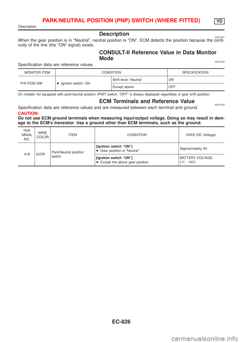
DescriptionNJEC0781When the gear position is in ªNeutralº, neutral position is ªONº. ECM detects the position because the conti-
nuity of the line (the ªONº signal) exists.
CONSULT-II Reference Value in Data Monitor
Mode
NJEC0782Specification data are reference values.
MONITOR ITEM CONDITION SPECIFICATION
P/N POSI SW+Ignition switch: ONShift lever: Neutral ON
Except above OFF
On models not equipped with park/neutral position (PNP) switch, ªOFFº is always displayed regardless of gear shift position.
ECM Terminals and Reference ValueNJEC0783Specification data are reference values and are measured between each terminal and ground.
CAUTION:
Do not use ECM ground terminals when measuring input/output voltage. Doing so may result in dam-
age to the ECM's transistor. Use a ground other than ECM terminals, such as the ground.
TER-
MINAL
NO.WIRE
COLORITEM CONDITION DATA (DC Voltage)
418 G/ORPark/Neutral position
switch[Ignition switch ªONº]
+Gear position is ªNeutralºApproximately 0V
[Ignition switch ªONº]
+Except the above gear positionBATTERY VOLTAGE
(11 - 14V)
PARK/NEUTRAL POSITION (PNP) SWITCH (WHERE FITTED)YD
Description
EC-826
Trending: wiper size, lug pattern, ECU, manual radio set, wheelbase, automatic transmission, window
