lock NISSAN ALMERA 2001 Owner's Manual
[x] Cancel search | Manufacturer: NISSAN, Model Year: 2001, Model line: ALMERA, Model: NISSAN ALMERA 2001Pages: 2898, PDF Size: 60.76 MB
Page 77 of 2898
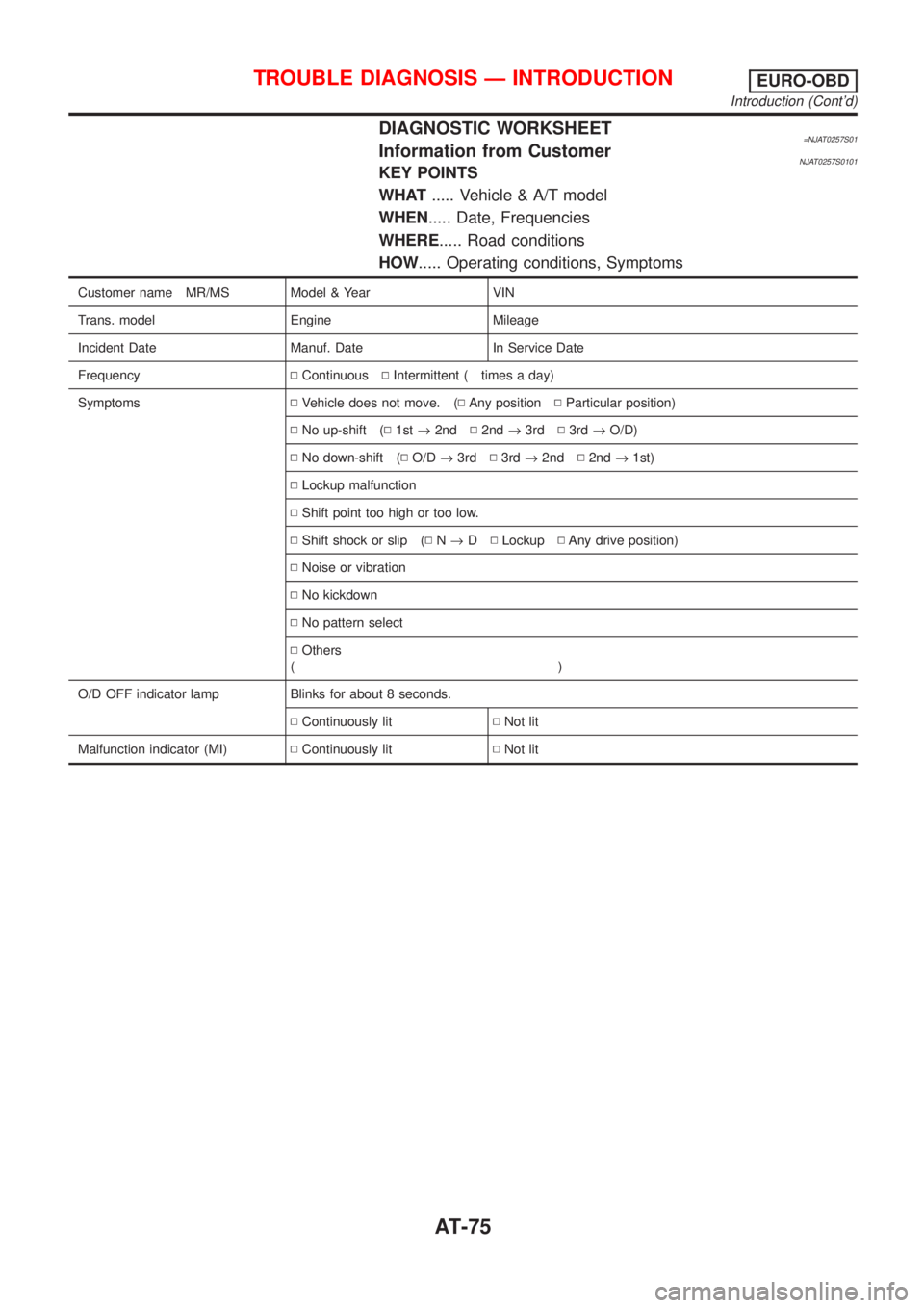
DIAGNOSTIC WORKSHEET=NJAT0257S01Information from CustomerNJAT0257S0101KEY POINTS
WHAT..... Vehicle & A/T model
WHEN..... Date, Frequencies
WHERE..... Road conditions
HOW..... Operating conditions, Symptoms
Customer name MR/MS Model & Year VIN
Trans. model Engine Mileage
Incident Date Manuf. Date In Service Date
FrequencyNContinuousNIntermittent ( times a day)
SymptomsNVehicle does not move. (NAny positionNParticular position)
NNo up-shift (N1st®2ndN2nd®3rdN3rd®O/D)
NNo down-shift (NO/D®3rdN3rd®2ndN2nd®1st)
NLockup malfunction
NShift point too high or too low.
NShift shock or slip (NN®DNLockupNAny drive position)
NNoise or vibration
NNo kickdown
NNo pattern select
NOthers
()
O/D OFF indicator lamp Blinks for about 8 seconds.
NContinuously litNNot lit
Malfunction indicator (MI)NContinuously litNNot lit
TROUBLE DIAGNOSIS Ð INTRODUCTIONEURO-OBD
Introduction (Cont'd)
AT-75
Page 79 of 2898
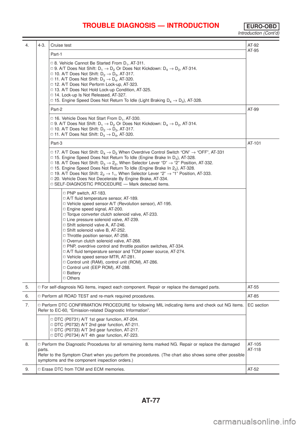
4. 4-3. Cruise testAT-92
AT-95
Part-1
N8. Vehicle Cannot Be Started From D
1, AT-311.
N9. A/T Does Not Shift: D
1®D2Or Does Not Kickdown: D4®D2, AT-314.
N10. A/T Does Not Shift: D
2®D3, AT-317.
N11. A/T Does Not Shift: D
3®D4, AT-320.
N12. A/T Does Not Perform Lock-up, AT-323.
N13. A/T Does Not Hold Lock-up Condition, AT-325.
N14. Lock-up Is Not Released, AT-327.
N15. Engine Speed Does Not Return To Idle (Light Braking D
4®D3), AT-328.
Part-2AT-99
N16. Vehicle Does Not Start From D
1, AT-330.
N9. A/T Does Not Shift: D
1®D2Or Does Not Kickdown: D4®D2, AT-314.
N10. A/T Does Not Shift: D
2®D3, AT-317.
N11. A/T Does Not Shift: D
3®D4, AT-320.
Part-3AT-101
N17. A/T Does Not Shift: D
4®D3When Overdrive Control Switch ªONº®ªOFFº, AT-331
N15. Engine Speed Does Not Return To Idle (Engine Brake In D
3), AT-328.
N18. A/T Does Not Shift: D
3®22, When Selector Lever ªDº®ª2º Position, AT-332.
N15. Engine Speed Does Not Return To Idle (Engine Brake In 2
2), AT-328.
N19. A/T Does Not Shift: 2
2®11, When Selector Lever ª2º®ª1º Position, AT-333.
N20. Vehicle Does Not Decelerate By Engine Brake, AT-334.
NSELF-DIAGNOSTIC PROCEDURE Ð Mark detected items.
NPNP switch, AT-183.
NA/T fluid temperature sensor, AT-189.
NVehicle speed sensor´A/T (Revolution sensor), AT-195.
NEngine speed signal, AT-200.
NTorque converter clutch solenoid valve, AT-233.
NLine pressure solenoid valve, AT-239.
NShift solenoid valve A, AT-246.
NShift solenoid valve B, AT-252.
NThrottle position sensor, AT-258.
NOverrun clutch solenoid valve, AT-268.
NPNP, overdrive control and throttle position switches, AT-334.
NA/T fluid temperature sensor and TCM power source, AT-274.
NVehicle speed sensor´MTR, AT-281.
NControl unit (RAM), control unit (ROM), AT-286.
NControl unit (EEP ROM), AT-288.
NBattery
NOthers
5.NFor self-diagnosis NG items, inspect each component. Repair or replace the damaged parts. AT-55
6.NPerform all ROAD TEST and re-mark required procedures. AT-85
7.NPerform DTC CONFIRMATION PROCEDURE for following MIL indicating items and check out NG items.
Refer to EC-60, ªEmission-related Diagnostic Informationº.EC section
NDTC (P0731) A/T 1st gear function, AT-204.
NDTC (P0732) A/T 2nd gear function, AT-211.
NDTC (P0733) A/T 3rd gear function, AT-217.
NDTC (P0734) A/T 4th gear function, AT-223.
8.NPerform the Diagnostic Procedures for all remaining items marked NG. Repair or replace the damaged
parts.
Refer to the Symptom Chart when you perform the procedures. (The chart also shows some other possible
symptoms and the component inspection orders.)AT-105
AT-118
9.NErase DTC from TCM and ECM memories. AT-52
TROUBLE DIAGNOSIS Ð INTRODUCTIONEURO-OBD
Introduction (Cont'd)
AT-77
Page 83 of 2898
SAT513G
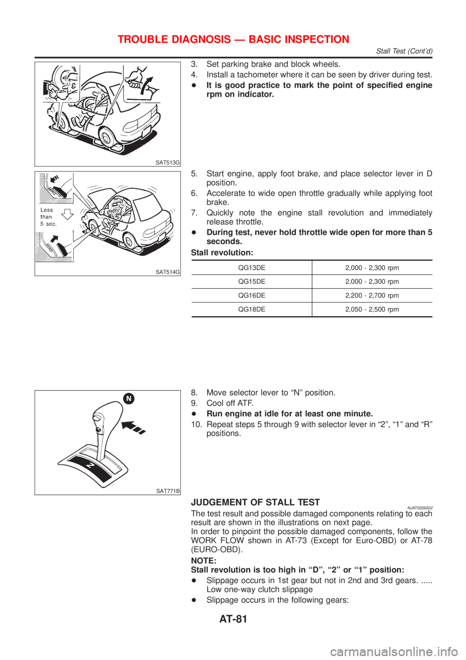
3. Set parking brake and block wheels.
4. Install a tachometer where it can be seen by driver during test.
+It is good practice to mark the point of specified engine
rpm on indicator.
SAT514G
5. Start engine, apply foot brake, and place selector lever in D
position.
6. Accelerate to wide open throttle gradually while applying foot
brake.
7. Quickly note the engine stall revolution and immediately
release throttle.
+During test, never hold throttle wide open for more than 5
seconds.
Stall revolution:
QG13DE 2,000 - 2,300 rpm
QG15DE 2,000 - 2,300 rpm
QG16DE 2,200 - 2,700 rpm
QG18DE 2,050 - 2,500 rpm
SAT771B
8. Move selector lever to ªNº position.
9. Cool off ATF.
+Run engine at idle for at least one minute.
10. Repeat steps 5 through 9 with selector lever in ª2º, ª1º and ªRº
positions.
JUDGEMENT OF STALL TESTNJAT0026S02The test result and possible damaged components relating to each
result are shown in the illustrations on next page.
In order to pinpoint the possible damaged components, follow the
WORK FLOW shown in AT-73 (Except for Euro-OBD) or AT-78
(EURO-OBD).
NOTE:
Stall revolution is too high in ªDº, ª2º or ª1º position:
+Slippage occurs in 1st gear but not in 2nd and 3rd gears. .....
Low one-way clutch slippage
+Slippage occurs in the following gears:
TROUBLE DIAGNOSIS Ð BASIC INSPECTION
Stall Test (Cont'd)
AT-81
Page 86 of 2898
SAT561J
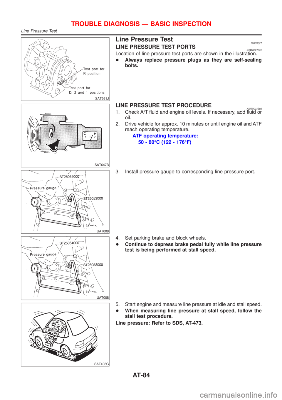
Line Pressure TestNJAT0027LINE PRESSURE TEST PORTSNJAT0027S01Location of line pressure test ports are shown in the illustration.
+Always replace pressure plugs as they are self-sealing
bolts.
SAT647B
LINE PRESSURE TEST PROCEDURENJAT0027S021. Check A/T fluid and engine oil levels. If necessary, add fluid or
oil.
2. Drive vehicle for approx. 10 minutes or until engine oil and ATF
reach operating temperature.
ATF operating temperature:
50 - 80ÉC (122 - 176ÉF)
UAT008
3. Install pressure gauge to corresponding line pressure port.
UAT008
4. Set parking brake and block wheels.
+Continue to depress brake pedal fully while line pressure
test is being performed at stall speed.
SAT493G
5. Start engine and measure line pressure at idle and stall speed.
+When measuring line pressure at stall speed, follow the
stall test procedure.
Line pressure: Refer to SDS, AT-473.
TROUBLE DIAGNOSIS Ð BASIC INSPECTION
Line Pressure Test
AT-84
Page 94 of 2898
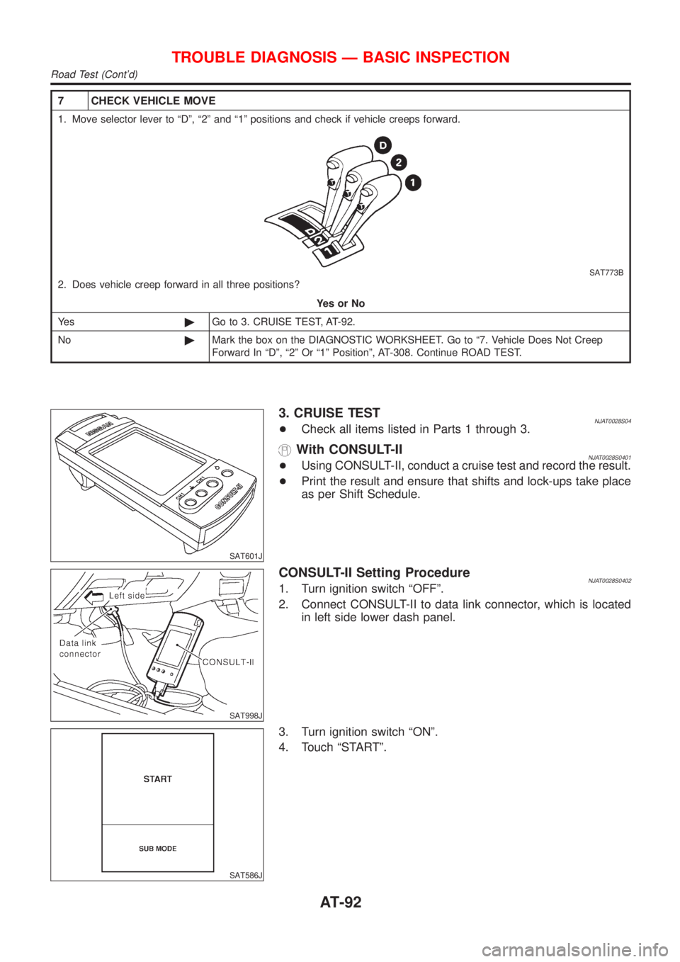
7 CHECK VEHICLE MOVE
1. Move selector lever to ªDº, ª2º and ª1º positions and check if vehicle creeps forward.
SAT773B
2. Does vehicle creep forward in all three positions?
YesorNo
Ye s©Go to 3. CRUISE TEST, AT-92.
No©Mark the box on the DIAGNOSTIC WORKSHEET. Go to ª7. Vehicle Does Not Creep
Forward In ªDº, ª2º Or ª1º Positionº, AT-308. Continue ROAD TEST.
SAT601J
3. CRUISE TESTNJAT0028S04+Check all items listed in Parts 1 through 3.
With CONSULT-IINJAT0028S0401+Using CONSULT-II, conduct a cruise test and record the result.
+Print the result and ensure that shifts and lock-ups take place
as per Shift Schedule.
SAT998J
CONSULT-II Setting ProcedureNJAT0028S04021. Turn ignition switch ªOFFº.
2. Connect CONSULT-II to data link connector, which is located
in left side lower dash panel.
SAT586J
3. Turn ignition switch ªONº.
4. Touch ªSTARTº.
TROUBLE DIAGNOSIS Ð BASIC INSPECTION
Road Test (Cont'd)
AT-92
Page 99 of 2898
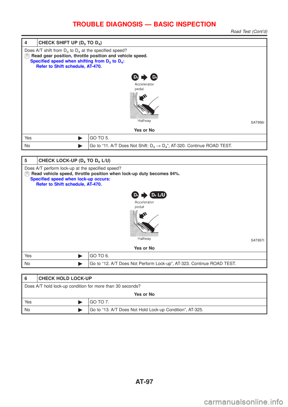
4 CHECK SHIFT UP (D3TO D4)
Does A/T shift from D3to D4at the specified speed?
Read gear position, throttle position and vehicle speed.
Specified speed when shifting from D
3to D4:
Refer to Shift schedule, AT-470.
SAT956I
YesorNo
Ye s©GO TO 5.
No©Go to ª11. A/T Does Not Shift: D
3®D4º, AT-320. Continue ROAD TEST.
5 CHECK LOCK-UP (D4TO D4L/U)
Does A/T perform lock-up at the specified speed?
Read vehicle speed, throttle position when lock-up duty becomes 94%.
Specified speed when lock-up occurs:
Refer to Shift schedule, AT-470.
SAT957I
YesorNo
Ye s©GO TO 6.
No©Go to ª12. A/T Does Not Perform Lock-upº, AT-323. Continue ROAD TEST.
6 CHECK HOLD LOCK-UP
Does A/T hold lock-up condition for more than 30 seconds?
YesorNo
Ye s©GO TO 7.
No©Go to ª13. A/T Does Not Hold Lock-up Conditionº, AT-325.
TROUBLE DIAGNOSIS Ð BASIC INSPECTION
Road Test (Cont'd)
AT-97
Page 100 of 2898
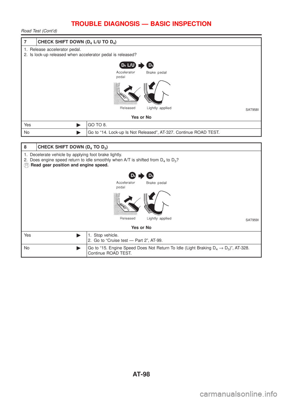
7 CHECK SHIFT DOWN (D4L/U TO D4)
1. Release accelerator pedal.
2. Is lock-up released when accelerator pedal is released?
SAT958I
YesorNo
Ye s©GO TO 8.
No©Go to ª14. Lock-up Is Not Releasedº, AT-327. Continue ROAD TEST.
8 CHECK SHIFT DOWN (D4TO D3)
1. Decelerate vehicle by applying foot brake lightly.
2. Does engine speed return to idle smoothly when A/T is shifted from D
4to D3?
Read gear position and engine speed.
SAT959I
YesorNo
Ye s©1. Stop vehicle.
2. Go to ªCruise test Ð Part 2º, AT-99.
No©Go to ª15. Engine Speed Does Not Return To Idle (Light Braking D
4®D3)º, AT-328.
Continue ROAD TEST.
TROUBLE DIAGNOSIS Ð BASIC INSPECTION
Road Test (Cont'd)
AT-98
Page 119 of 2898
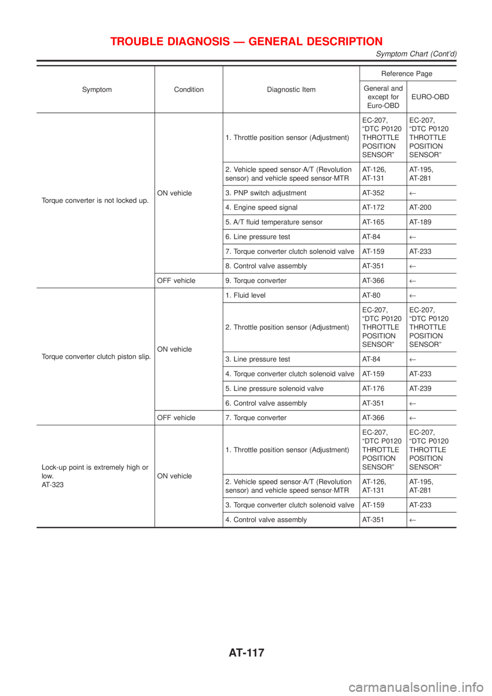
Symptom Condition Diagnostic ItemReference Page
General and
except for
Euro-OBDEURO-OBD
Torque converter is not locked up.ON vehicle1. Throttle position sensor (Adjustment)EC-207,
ªDTC P0120
THROTTLE
POSITION
SENSORºEC-207,
ªDTC P0120
THROTTLE
POSITION
SENSORº
2. Vehicle speed sensor´A/T (Revolution
sensor) and vehicle speed sensor´MTRAT-126,
AT-131AT-195,
AT-281
3. PNP switch adjustment AT-352¬
4. Engine speed signal AT-172 AT-200
5. A/T fluid temperature sensor AT-165 AT-189
6. Line pressure test AT-84¬
7. Torque converter clutch solenoid valve AT-159 AT-233
8. Control valve assembly AT-351¬
OFF vehicle 9. Torque converter AT-366¬
Torque converter clutch piston slip.ON vehicle1. Fluid level AT-80¬
2. Throttle position sensor (Adjustment)EC-207,
ªDTC P0120
THROTTLE
POSITION
SENSORºEC-207,
ªDTC P0120
THROTTLE
POSITION
SENSORº
3. Line pressure test AT-84¬
4. Torque converter clutch solenoid valve AT-159 AT-233
5. Line pressure solenoid valve AT-176 AT-239
6. Control valve assembly AT-351¬
OFF vehicle 7. Torque converter AT-366¬
Lock-up point is extremely high or
low.
AT-323ON vehicle1. Throttle position sensor (Adjustment)EC-207,
ªDTC P0120
THROTTLE
POSITION
SENSORºEC-207,
ªDTC P0120
THROTTLE
POSITION
SENSORº
2. Vehicle speed sensor´A/T (Revolution
sensor) and vehicle speed sensor´MTRAT-126,
AT-131AT-195,
AT-281
3. Torque converter clutch solenoid valve AT-159 AT-233
4. Control valve assembly AT-351¬
TROUBLE DIAGNOSIS Ð GENERAL DESCRIPTION
Symptom Chart (Cont'd)
AT-117
Page 121 of 2898
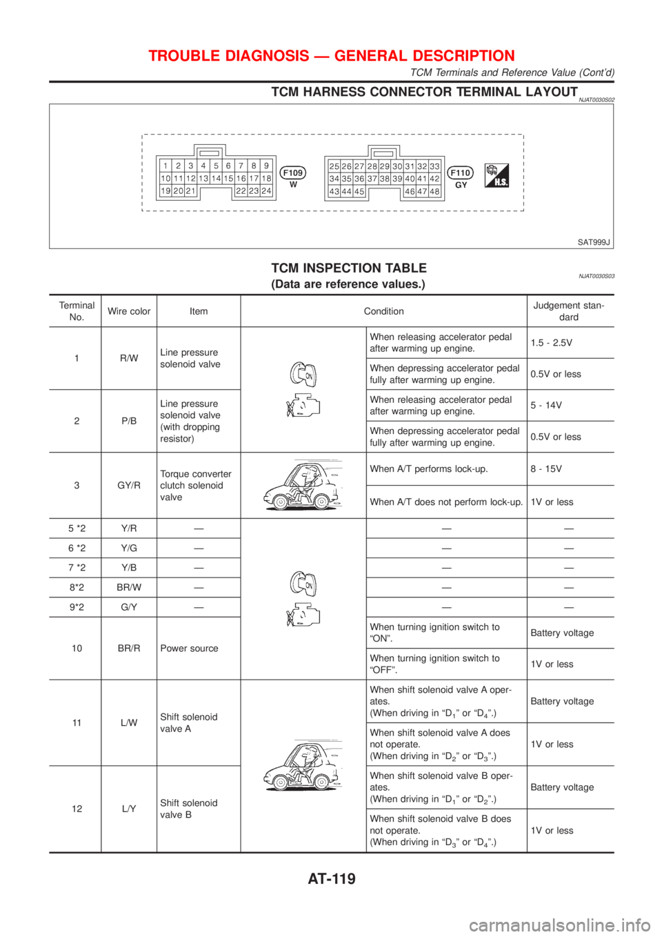
TCM HARNESS CONNECTOR TERMINAL LAYOUTNJAT0030S02
SAT999J
TCM INSPECTION TABLENJAT0030S03(Data are reference values.)
Terminal
No.Wire color Item ConditionJudgement stan-
dard
1 R/WLine pressure
solenoid valve
When releasing accelerator pedal
after warming up engine.1.5 - 2.5V
When depressing accelerator pedal
fully after warming up engine.0.5V or less
2 P/BLine pressure
solenoid valve
(with dropping
resistor)When releasing accelerator pedal
after warming up engine.5 - 14V
When depressing accelerator pedal
fully after warming up engine.0.5V or less
3 GY/RTorque converter
clutch solenoid
valve
When A/T performs lock-up. 8 - 15V
When A/T does not perform lock-up. 1V or less
5 *2 Y/R Ð
ÐÐ
6 *2 Y/G Ð Ð Ð
7 *2 Y/B Ð Ð Ð
8*2 BR/W Ð Ð Ð
9*2 G/Y Ð Ð Ð
10 BR/R Power sourceWhen turning ignition switch to
ªONº.Battery voltage
When turning ignition switch to
ªOFFº.1V or less
11 L/WShift solenoid
valve A
When shift solenoid valve A oper-
ates.
(When driving in ªD
1ºorªD4º.)Battery voltage
When shift solenoid valve A does
not operate.
(When driving in ªD
2ºorªD3º.)1V or less
12 L/YShift solenoid
valve BWhen shift solenoid valve B oper-
ates.
(When driving in ªD
1ºorªD2º.)Battery voltage
When shift solenoid valve B does
not operate.
(When driving in ªD
3ºorªD4º.)1V or less
TROUBLE DIAGNOSIS Ð GENERAL DESCRIPTION
TCM Terminals and Reference Value (Cont'd)
AT-119
Page 128 of 2898
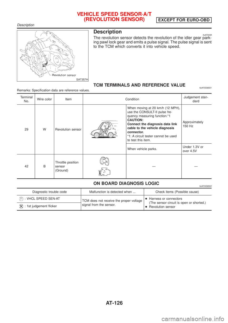
SAT357H
DescriptionNJAT0038The revolution sensor detects the revolution of the idler gear park-
ing pawl lock gear and emits a pulse signal. The pulse signal is sent
to the TCM which converts it into vehicle speed.
TCM TERMINALS AND REFERENCE VALUENJAT0038S01Remarks: Specification data are reference values.
Terminal
No.Wire color Item ConditionJudgement stan-
dard
29 W Revolution sensor
When moving at 20 km/h (12 MPH),
use the CONSULT-II pulse fre-
quency measuring function.*1
CAUTION:
Connect the diagnosis data link
cable to the vehicle diagnosis
connector.
*1: A circuit tester cannot be used
to test this item.Approximately
150 Hz
When vehicle parks.Under 1.3V or
over 4.5V
42 BThrottle position
sensor
(Ground)
ÐÐ
ON BOARD DIAGNOSIS LOGICNJAT0038S02
Diagnostic trouble code Malfunction is detected when ... Check items (Possible cause)
: VHCL SPEED SEN´AT
TCM does not receive the proper voltage
signal from the sensor.+Harness or connectors
(The sensor circuit is open or shorted.)
+Revolution sensor
: 1st judgement flicker
VEHICLE SPEED SENSOR´A/T
(REVOLUTION SENSOR)
EXCEPT FOR EURO-OBD
Description
AT-126