NISSAN ALMERA 2001 Workshop Manual
ALMERA 2001
NISSAN
NISSAN
https://www.carmanualsonline.info/img/5/57348/w960_57348-0.png
NISSAN ALMERA 2001 Workshop Manual
Page 368 of 2898
NJAT0120
SAT049K
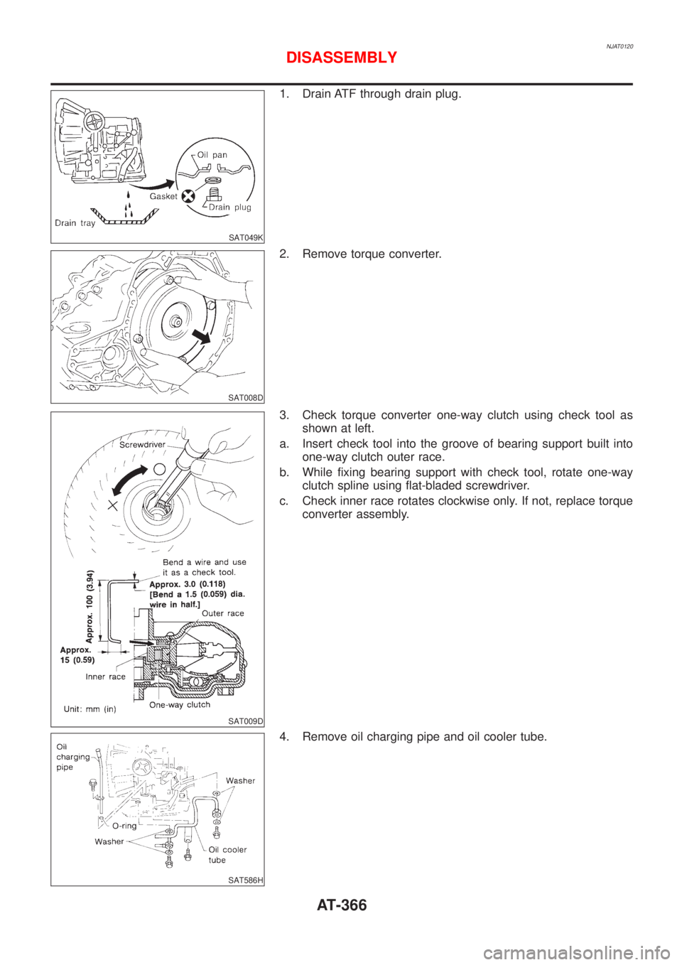
1. Drain ATF through drain plug.
SAT008D
2. Remove torque converter.
SAT009D
3. Check torque converter one-way clutch using check tool as
shown at left.
a. Insert check tool into the groove of bearing support built into
one-way clutch outer race.
b. While fixing bearing support with check tool, rotate one-way
clutch spline using flat-bladed screwdriver.
c. Check inner race rotates clockwise only. If not, replace torque
converter assembly.
SAT586H
4. Remove oil charging pipe and oil cooler tube.
DISASSEMBLY
AT-366
Page 374 of 2898
SAT037DA
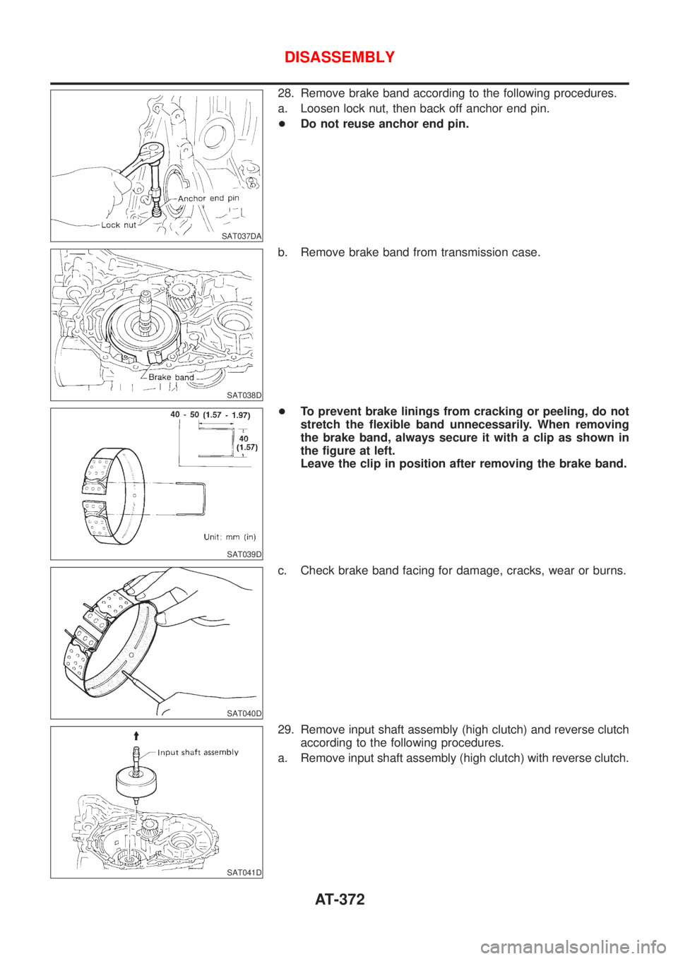
28. Remove brake band according to the following procedures.
a. Loosen lock nut, then back off anchor end pin.
+Do not reuse anchor end pin.
SAT038D
b. Remove brake band from transmission case.
SAT039D
+To prevent brake linings from cracking or peeling, do not
stretch the flexible band unnecessarily. When removing
the brake band, always secure it with a clip as shown in
the figure at left.
Leave the clip in position after removing the brake band.
SAT040D
c. Check brake band facing for damage, cracks, wear or burns.
SAT041D
29. Remove input shaft assembly (high clutch) and reverse clutch
according to the following procedures.
a. Remove input shaft assembly (high clutch) with reverse clutch.
DISASSEMBLY
AT-372
Page 376 of 2898
SAT047D
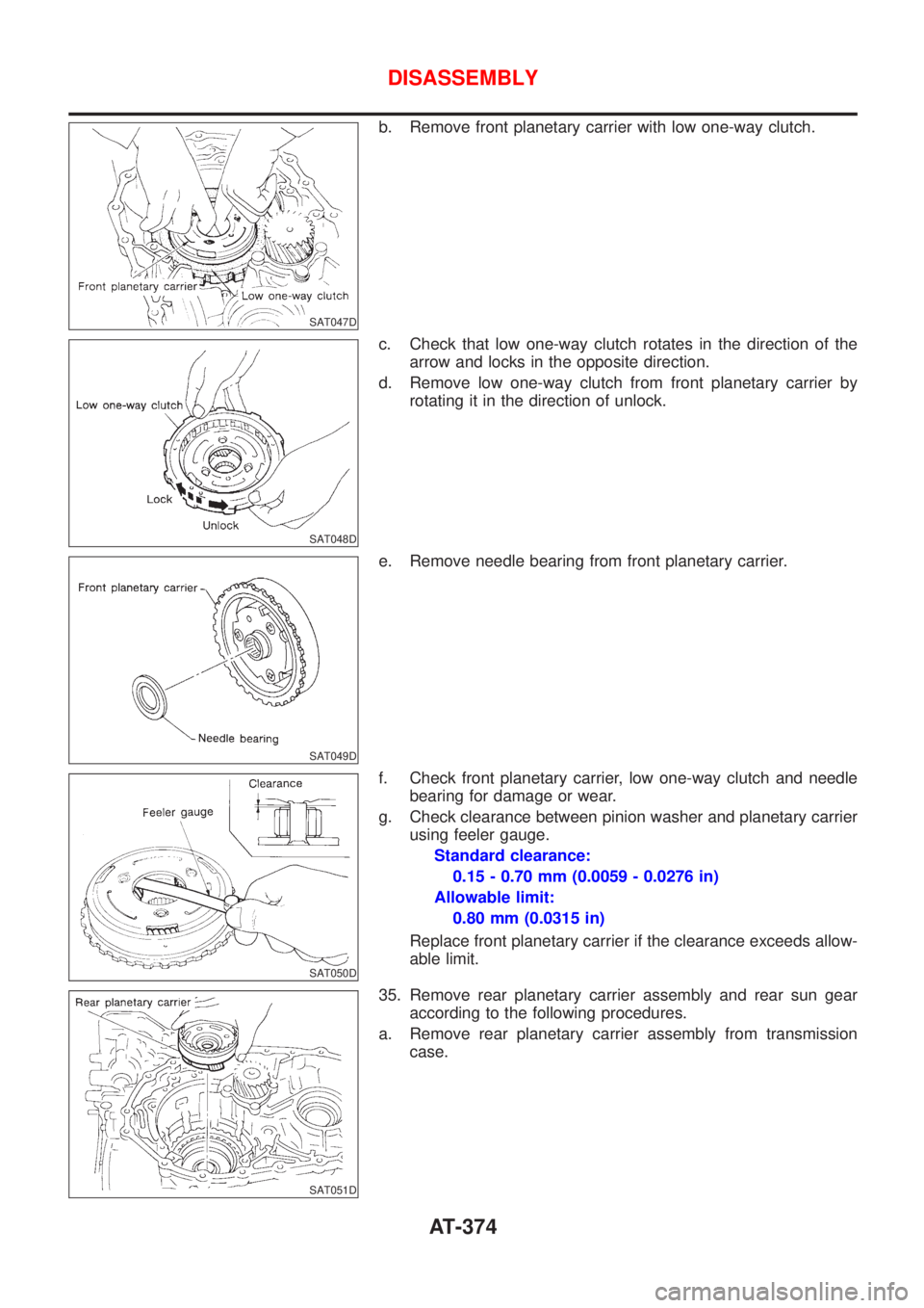
b. Remove front planetary carrier with low one-way clutch.
SAT048D
c. Check that low one-way clutch rotates in the direction of the
arrow and locks in the opposite direction.
d. Remove low one-way clutch from front planetary carrier by
rotating it in the direction of unlock.
SAT049D
e. Remove needle bearing from front planetary carrier.
SAT050D
f. Check front planetary carrier, low one-way clutch and needle
bearing for damage or wear.
g. Check clearance between pinion washer and planetary carrier
using feeler gauge.
Standard clearance:
0.15 - 0.70 mm (0.0059 - 0.0276 in)
Allowable limit:
0.80 mm (0.0315 in)
Replace front planetary carrier if the clearance exceeds allow-
able limit.
SAT051D
35. Remove rear planetary carrier assembly and rear sun gear
according to the following procedures.
a. Remove rear planetary carrier assembly from transmission
case.
DISASSEMBLY
AT-374
Page 378 of 2898
SAT272E
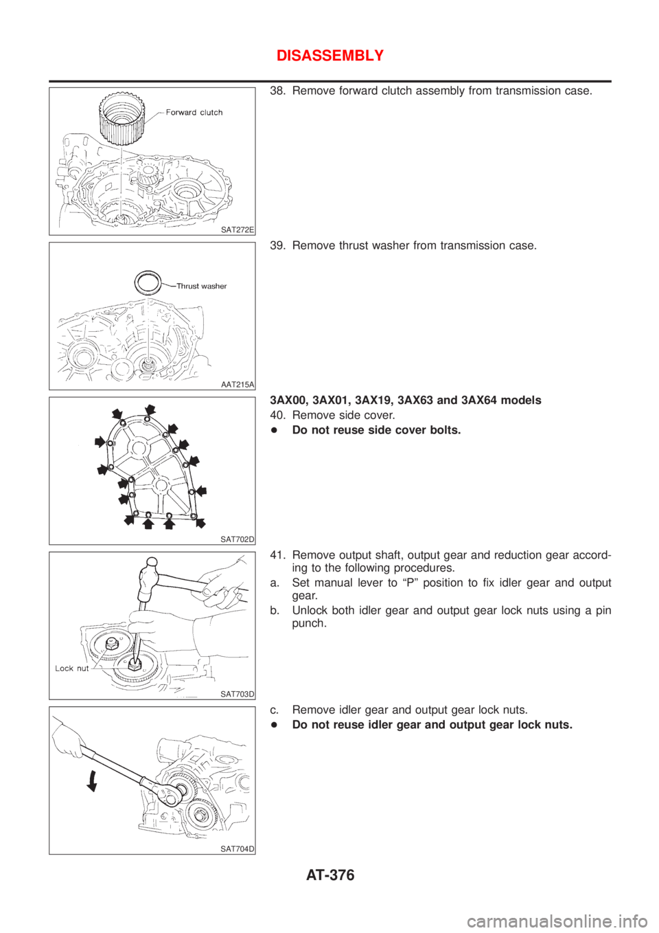
38. Remove forward clutch assembly from transmission case.
AAT215A
39. Remove thrust washer from transmission case.
SAT702D
3AX00, 3AX01, 3AX19, 3AX63 and 3AX64 models
40. Remove side cover.
+Do not reuse side cover bolts.
SAT703D
41. Remove output shaft, output gear and reduction gear accord-
ing to the following procedures.
a. Set manual lever to ªPº position to fix idler gear and output
gear.
b. Unlock both idler gear and output gear lock nuts using a pin
punch.
SAT704D
c. Remove idler gear and output gear lock nuts.
+Do not reuse idler gear and output gear lock nuts.
DISASSEMBLY
AT-376
Page 380 of 2898
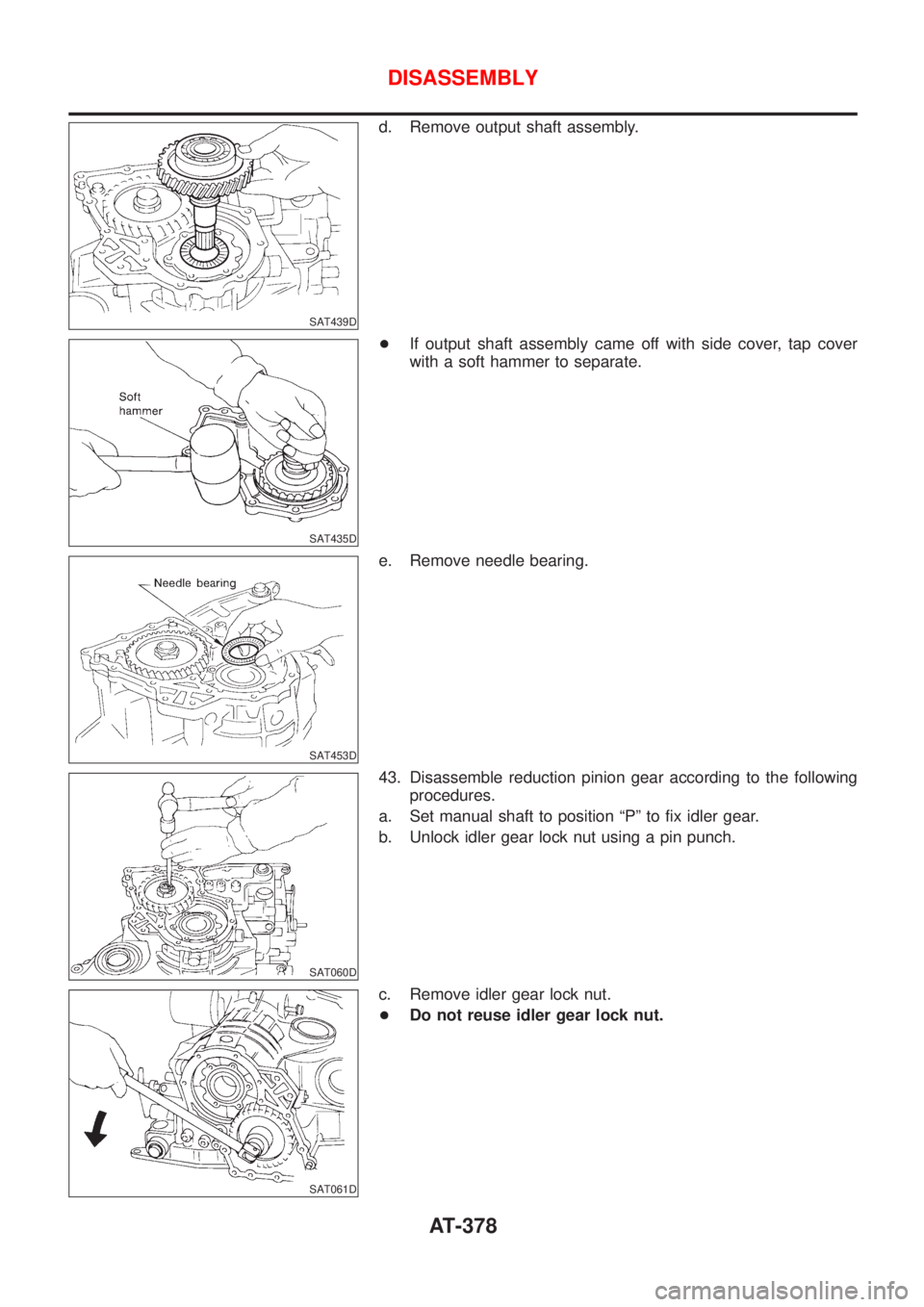
SAT439D
d. Remove output shaft assembly.
SAT435D
+If output shaft assembly came off with side cover, tap cover
with a soft hammer to separate.
SAT453D
e. Remove needle bearing.
SAT060D
43. Disassemble reduction pinion gear according to the following
procedures.
a. Set manual shaft to position ªPº to fix idler gear.
b. Unlock idler gear lock nut using a pin punch.
SAT061D
c. Remove idler gear lock nut.
+Do not reuse idler gear lock nut.
DISASSEMBLY
AT-378
Page 428 of 2898
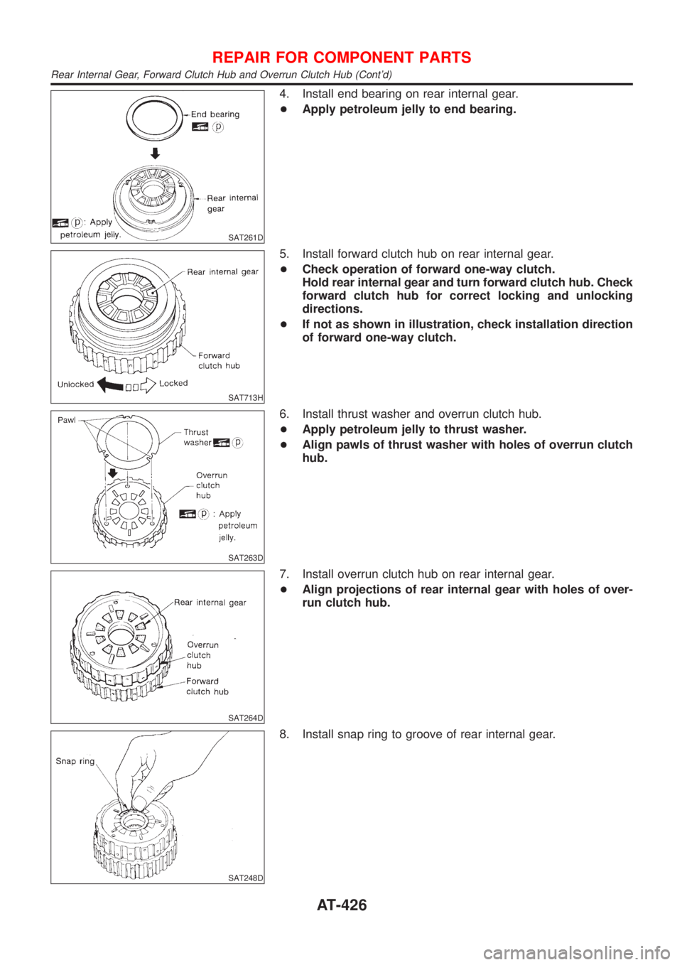
SAT261D
4. Install end bearing on rear internal gear.
+Apply petroleum jelly to end bearing.
SAT713H
5. Install forward clutch hub on rear internal gear.
+Check operation of forward one-way clutch.
Hold rear internal gear and turn forward clutch hub. Check
forward clutch hub for correct locking and unlocking
directions.
+If not as shown in illustration, check installation direction
of forward one-way clutch.
SAT263D
6. Install thrust washer and overrun clutch hub.
+Apply petroleum jelly to thrust washer.
+Align pawls of thrust washer with holes of overrun clutch
hub.
SAT264D
7. Install overrun clutch hub on rear internal gear.
+Align projections of rear internal gear with holes of over-
run clutch hub.
SAT248D
8. Install snap ring to groove of rear internal gear.
REPAIR FOR COMPONENT PARTS
Rear Internal Gear, Forward Clutch Hub and Overrun Clutch Hub (Cont'd)
AT-426
Page 440 of 2898
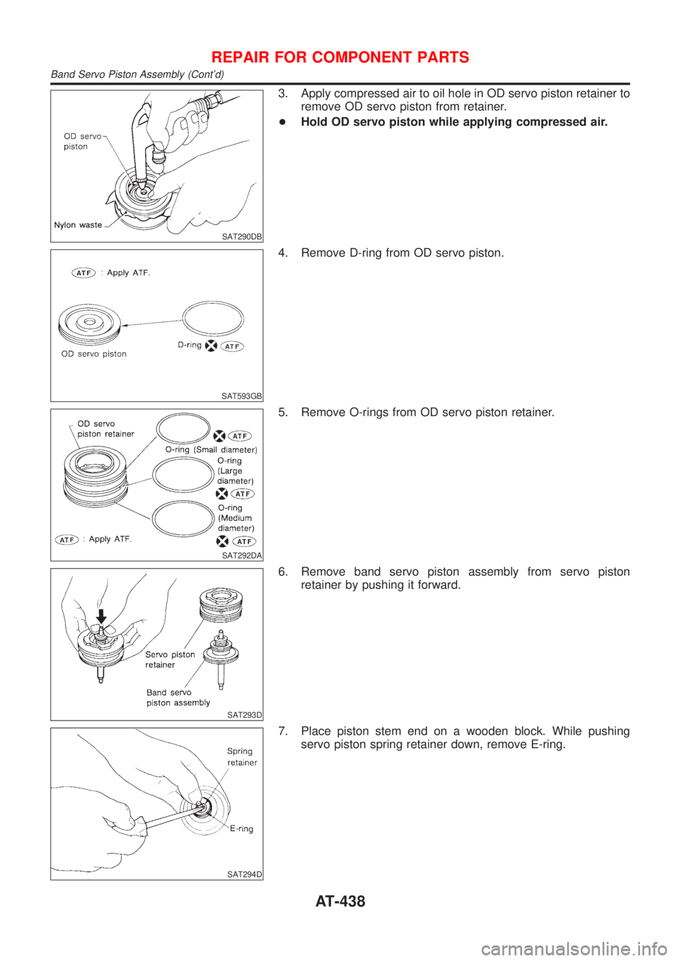
SAT290DB
3. Apply compressed air to oil hole in OD servo piston retainer to
remove OD servo piston from retainer.
+Hold OD servo piston while applying compressed air.
SAT593GB
4. Remove D-ring from OD servo piston.
SAT292DA
5. Remove O-rings from OD servo piston retainer.
SAT293D
6. Remove band servo piston assembly from servo piston
retainer by pushing it forward.
SAT294D
7. Place piston stem end on a wooden block. While pushing
servo piston spring retainer down, remove E-ring.
REPAIR FOR COMPONENT PARTS
Band Servo Piston Assembly (Cont'd)
AT-438
Page 442 of 2898
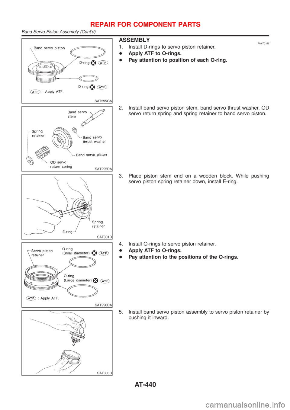
SAT595GA
ASSEMBLYNJAT01681. Install D-rings to servo piston retainer.
+Apply ATF to O-rings.
+Pay attention to position of each O-ring.
SAT295DA
2. Install band servo piston stem, band servo thrust washer, OD
servo return spring and spring retainer to band servo piston.
SAT301D
3. Place piston stem end on a wooden block. While pushing
servo piston spring retainer down, install E-ring.
SAT296DA
4. Install O-rings to servo piston retainer.
+Apply ATF to O-rings.
+Pay attention to the positions of the O-rings.
SAT303D
5. Install band servo piston assembly to servo piston retainer by
pushing it inward.
REPAIR FOR COMPONENT PARTS
Band Servo Piston Assembly (Cont'd)
AT-440
Page 445 of 2898
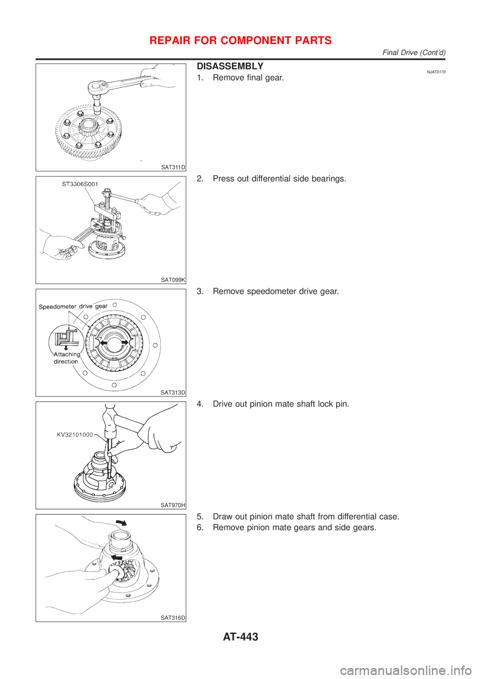
SAT311D
DISASSEMBLYNJAT01701. Remove final gear.
SAT099K
2. Press out differential side bearings.
SAT313D
3. Remove speedometer drive gear.
SAT970H
4. Drive out pinion mate shaft lock pin.
SAT316D
5. Draw out pinion mate shaft from differential case.
6. Remove pinion mate gears and side gears.
REPAIR FOR COMPONENT PARTS
Final Drive (Cont'd)
AT-443
Page 447 of 2898
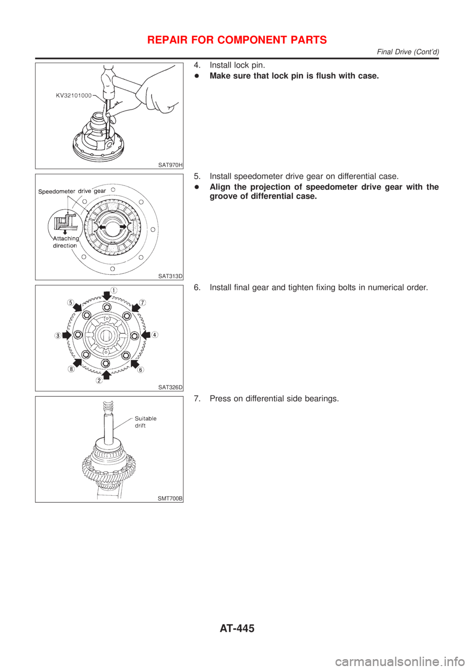
SAT970H
4. Install lock pin.
+Make sure that lock pin is flush with case.
SAT313D
5. Install speedometer drive gear on differential case.
+Align the projection of speedometer drive gear with the
groove of differential case.
SAT326D
6. Install final gear and tighten fixing bolts in numerical order.
SMT700B
7. Press on differential side bearings.
REPAIR FOR COMPONENT PARTS
Final Drive (Cont'd)
AT-445
