o2 sensor NISSAN ALMERA 2001 Service Manual
[x] Cancel search | Manufacturer: NISSAN, Model Year: 2001, Model line: ALMERA, Model: NISSAN ALMERA 2001Pages: 2898, PDF Size: 60.76 MB
Page 1375 of 2898
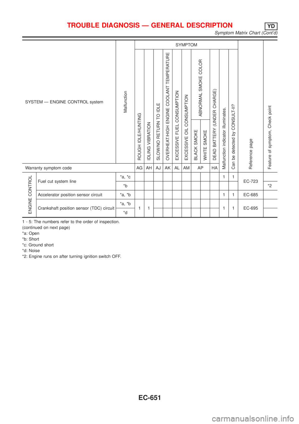
SYSTEM Ð ENGINE CONTROL system
Malfunction
SYMPTOM
Reference page
Feature of symptom, Check pointROUGH IDLE/HUNTING
IDLING VIBRATION
SLOW/NO RETURN TO IDLE
OVERHEAT/HIGH ENGINE COOLANT TEMPERATURE
EXCESSIVE FUEL CONSUMPTION
EXCESSIVE OIL CONSUMPTION
ABNORMAL SMOKE COLOR
DEAD BATTERY (UNDER CHARGE)
Malfunction indicator illuminates.
Can be detected by CONSULT-II?BLACK SMOKE
WHITE SMOKEWarranty symptom code AG AH AJ AK AL AM AP HA
ENGINE CONTROL
Fuel cut system line*a, *c 1 1
EC-723
*b*2
Accelerator position sensor circuit *a, *b 1 1 EC-685
Crankshaft position sensor (TDC) circuit*a, *b
1 1 1 1 EC-695
*d
1 - 5: The numbers refer to the order of inspection.
(continued on next page)
*a: Open
*b: Short
*c: Ground short
*d: Noise
*2: Engine runs on after turning ignition switch OFF.
TROUBLE DIAGNOSIS Ð GENERAL DESCRIPTIONYD
Symptom Matrix Chart (Cont'd)
EC-651
Page 1376 of 2898
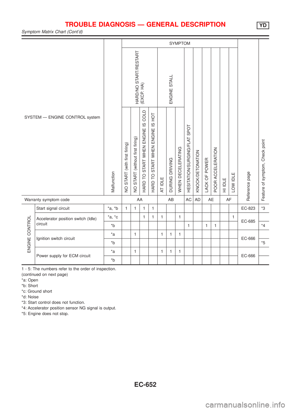
SYSTEM Ð ENGINE CONTROL system
Malfunction
SYMPTOM
Reference page
Feature of symptom, Check pointHARD/NO START/RESTART
(EXCP. HA)
ENGINE STALL
HESITATION/SURGING/FLAT SPOT
KNOCK/DETONATION
LACK OF POWER
POOR ACCELERATION
HI IDLE
LOW IDLE NO START (with first firing)
NO START (without first firing)
HARD TO START WHEN ENGINE IS COLD
HARD TO START WHEN ENGINE IS HOT
AT IDLE
DURING DRIVING
WHEN DECELERATINGWarranty symptom code AA AB AC AD AE AF
ENGINE CONTROL
Start signal circuit *a, *b1111EC-823 *3
Accelerator position switch (Idle)
circuit*a, *c 1 1 1 1 1
EC-685
*b 1 1 1 *4
Ignition switch circuit*a 1 111
EC-666
*b*5
Power supply for ECM circuit*a 1 111
EC-666
*b
1 - 5: The numbers refer to the order of inspection.
(continued on next page)
*a: Open
*b: Short
*c: Ground short
*d: Noise
*3: Start control does not function.
*4: Accelerator position sensor NG signal is output.
*5: Engine does not stop.
TROUBLE DIAGNOSIS Ð GENERAL DESCRIPTIONYD
Symptom Matrix Chart (Cont'd)
EC-652
Page 1377 of 2898
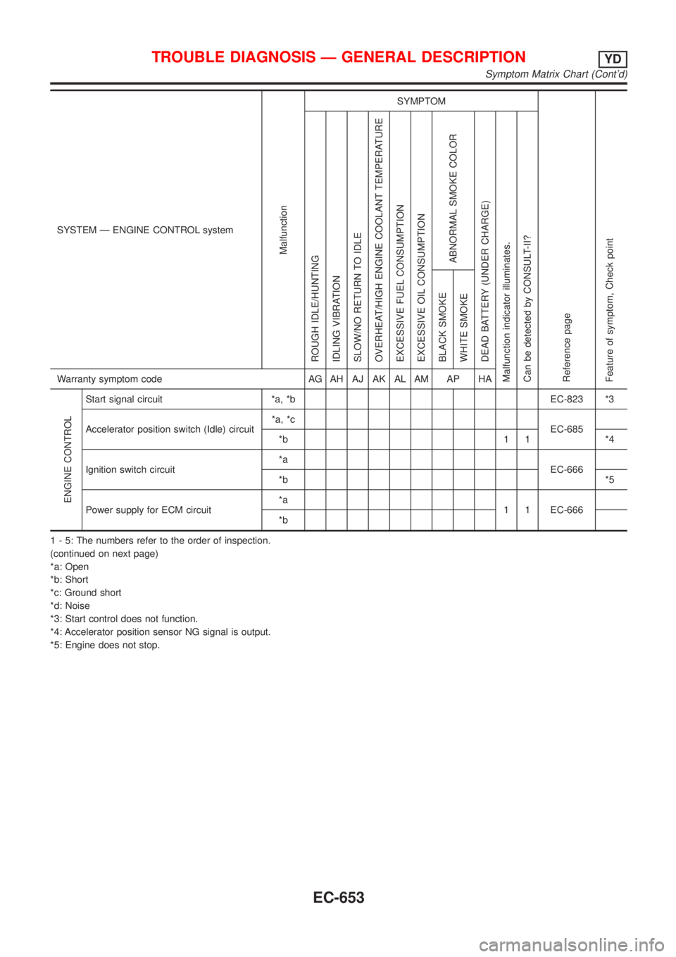
SYSTEM Ð ENGINE CONTROL system
Malfunction
SYMPTOM
Reference page
Feature of symptom, Check pointROUGH IDLE/HUNTING
IDLING VIBRATION
SLOW/NO RETURN TO IDLE
OVERHEAT/HIGH ENGINE COOLANT TEMPERATURE
EXCESSIVE FUEL CONSUMPTION
EXCESSIVE OIL CONSUMPTION
ABNORMAL SMOKE COLOR
DEAD BATTERY (UNDER CHARGE)
Malfunction indicator illuminates.
Can be detected by CONSULT-II?BLACK SMOKE
WHITE SMOKEWarranty symptom code AG AH AJ AK AL AM AP HA
ENGINE CONTROL
Start signal circuit *a, *b EC-823 *3
Accelerator position switch (Idle) circuit*a, *c
EC-685
*b 1 1 *4
Ignition switch circuit*a
EC-666
*b*5
Power supply for ECM circuit*a
1 1 EC-666
*b
1 - 5: The numbers refer to the order of inspection.
(continued on next page)
*a: Open
*b: Short
*c: Ground short
*d: Noise
*3: Start control does not function.
*4: Accelerator position sensor NG signal is output.
*5: Engine does not stop.
TROUBLE DIAGNOSIS Ð GENERAL DESCRIPTIONYD
Symptom Matrix Chart (Cont'd)
EC-653
Page 1382 of 2898
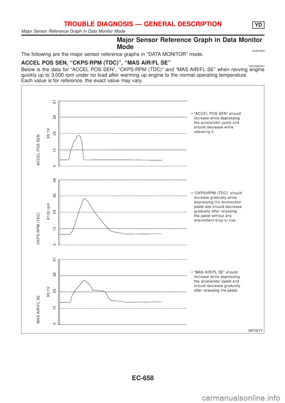
Major Sensor Reference Graph in Data Monitor
Mode
=NJEC0635The following are the major sensor reference graphs in ªDATA MONITORº mode.
ACCEL POS SEN, ªCKPS´RPM (TDC)º, ªMAS AIR/FL SEºNJEC0635S01Below is the data for ªACCEL POS SENº, ªCKPS´RPM (TDC)º and ªMAS AIR/FL SEº when revving engine
quickly up to 3,000 rpm under no load after warming up engine to the normal operating temperature.
Each value is for reference, the exact value may vary.
SEF321Y
TROUBLE DIAGNOSIS Ð GENERAL DESCRIPTIONYD
Major Sensor Reference Graph in Data Monitor Mode
EC-658
Page 1385 of 2898
![NISSAN ALMERA 2001 Service Manual TERMI-
NAL
NO.WIRE
COLORITEM CONDITIONDATA (DC Voltage and Pulse
Signal)
104
105
106B
B
BECM ground[Engine is running]
+Idle speedApproximately 0V
107
108
109R
R
RPower supply for ECM[Ignition switch NISSAN ALMERA 2001 Service Manual TERMI-
NAL
NO.WIRE
COLORITEM CONDITIONDATA (DC Voltage and Pulse
Signal)
104
105
106B
B
BECM ground[Engine is running]
+Idle speedApproximately 0V
107
108
109R
R
RPower supply for ECM[Ignition switch](/img/5/57348/w960_57348-1384.png)
TERMI-
NAL
NO.WIRE
COLORITEM CONDITIONDATA (DC Voltage and Pulse
Signal)
104
105
106B
B
BECM ground[Engine is running]
+Idle speedApproximately 0V
107
108
109R
R
RPower supply for ECM[Ignition switch ªONº]BATTERY VOLTAGE
(11 - 14V)
204 L Air conditioner relay[Engine is running]
+Air conditioner switch is ªOFFºBATTERY VOLTAGE
(11 - 14V)
[Engine is running]
+Both air conditioner switch and blower fan
switch are ªONº
(Compressor is operating)Approximately 0.1V
214 W/B Glow relay Refer to ªGlow Control Systemº, EC-806.
218 B Sensors' ground[Engine is running]
+Warm-up condition
+Idle speedApproximately 0V
219 LG/R Cooling fan relay (Low)[Engine is running]
+Cooling fan is not operatingBATTERY VOLTAGE
(11 - 14V)
[Engine is running]
+Cooling fan is operatingApproximately 0.1V
221 LG/B Cooling fan relay (High)[Engine is running]
+Cooling fan is not operating
+Cooling fan is operating at low speedBATTERY VOLTAGE
(11 - 14V)
[Engine is running]
+Cooling fan is operating at high speedApproximately 0.1V
223 WMass air flow sensor
power supply[Ignition switch ªONº]Approximately 5V
224 R Mass air flow sensor[Engine is running]
+Warm-up condition
+Idle speed1.5 - 2.0V
313 L/WElectronic control fuel
injection pump[Engine is running]
+Warm-up condition
+Idle speedApproximately 0.1V
314 L/RElectronic control fuel
injection pump[Engine is running]
+Warm-up condition
+Idle speedApproximately 0.4V
316 PUElectronic control fuel
injection pump[Engine is running]
+Warm-up condition
+Idle speedApproximately 2.5V
317 PElectronic control fuel
injection pump[Engine is running]
+Warm-up condition
+Idle speedApproximately 2.5V
325 G ECM relay (Self-shutoff)[Ignition switch ªONº]
[Ignition switch ªOFFº]
+For a few seconds after turning ignition switch
ªOFFºApproximately 0.25V
[Ignition switch ªOFFº]
+A few seconds passed after turning ignition
switch ªOFFºBATTERY VOLTAGE
(11 - 14V)
TROUBLE DIAGNOSIS Ð GENERAL DESCRIPTIONYD
ECM Terminals and Reference Value (Cont'd)
EC-661
Page 1386 of 2898
![NISSAN ALMERA 2001 Service Manual TERMI-
NAL
NO.WIRE
COLORITEM CONDITIONDATA (DC Voltage and Pulse
Signal)
331 ORCrankshaft position sen-
sor (TDC) ground[Engine is running]
+Warm-up condition
+Idle speedApproximately 0V
334 B/REngine NISSAN ALMERA 2001 Service Manual TERMI-
NAL
NO.WIRE
COLORITEM CONDITIONDATA (DC Voltage and Pulse
Signal)
331 ORCrankshaft position sen-
sor (TDC) ground[Engine is running]
+Warm-up condition
+Idle speedApproximately 0V
334 B/REngine](/img/5/57348/w960_57348-1385.png)
TERMI-
NAL
NO.WIRE
COLORITEM CONDITIONDATA (DC Voltage and Pulse
Signal)
331 ORCrankshaft position sen-
sor (TDC) ground[Engine is running]
+Warm-up condition
+Idle speedApproximately 0V
334 B/REngine coolant tempera-
ture sensor ground[Ignition switch ªONº]Approximately 0V
337
338
350
351W/L
PU/W
GY
OR/BEGR volume control
valve[Engine is running]
+Warm-up condition
+Idle speed0.1 - 14V
(Voltage signals of each ECM
terminals differ according to the
control position of EGR volume
control valve.)
344 WCrankshaft position sen-
sor (TDC)[Engine is running]
+Warm-up condition
+Idle speedApproximately 0V
SEF333Y
[Engine is running]
+Warm-up condition
+Engine speed is 2,000 rpmApproximately 0V
SEF334Y
347 L/BEngine coolant tempera-
ture sensor[Engine is running]Approximately 0 - 4.8V
Output voltage varies with
engine coolant temperature
403 R/L Air conditioner switch[Engine is running]
+Air conditioner switch is ªOFFºBATTERY VOLTAGE
(11 - 14V)
[Engine is running]
+Both air conditioner switch and blower fan
switch are ªONº
(Compressor is operating)Approximately 0.1V
405 R/G Stop lamp switch[Ignition switch ªONº]
+Brake pedal fully releasedApproximately 0V
[Ignition switch ªONº]
+Brake pedal depressedBATTERY VOLTAGE
(11 - 14V)
416 Y/BBrake pedal position
switch[Ignition switch ªONº]
+Brake pedal fully releasedBATTERY VOLTAGE
(11 - 14V)
[Ignition switch ªONº]
+Brake pedal depressedApproximately 0V
TROUBLE DIAGNOSIS Ð GENERAL DESCRIPTIONYD
ECM Terminals and Reference Value (Cont'd)
EC-662
Page 1387 of 2898
![NISSAN ALMERA 2001 Service Manual TERMI-
NAL
NO.WIRE
COLORITEM CONDITIONDATA (DC Voltage and Pulse
Signal)
417 PU/R Vehicle speed sensor[Engine is running]
+Lift up the vehicle
+In 1st gear position
+Vehicle speed is 10 km/h (6 MPH)0 NISSAN ALMERA 2001 Service Manual TERMI-
NAL
NO.WIRE
COLORITEM CONDITIONDATA (DC Voltage and Pulse
Signal)
417 PU/R Vehicle speed sensor[Engine is running]
+Lift up the vehicle
+In 1st gear position
+Vehicle speed is 10 km/h (6 MPH)0](/img/5/57348/w960_57348-1386.png)
TERMI-
NAL
NO.WIRE
COLORITEM CONDITIONDATA (DC Voltage and Pulse
Signal)
417 PU/R Vehicle speed sensor[Engine is running]
+Lift up the vehicle
+In 1st gear position
+Vehicle speed is 10 km/h (6 MPH)0 - Approximately 8V
SEF891Y
[Engine is running]
+Lift up the vehicle
+In 2nd gear position
+Vehicle speed is 30 km/h (19 MPH)Approximately 6V
SEF892Y
418 G/ORPark/Neutral position
switch (where fitted)[Ignition switch ªONº]
+Gear position is ªNeutralºApproximately 0V
[Ignition switch ªONº]
+Except the above gear positionBATTERY VOLTAGE
(11 - 14V)
422 B/Y Start signal[Ignition switch ªONº]Approximately 0V
[Ignition switch ªSTARTº]BATTERY VOLTAGE
(11 - 14V)
425 P/BAccelerator position sen-
sor ground[Engine is running]
+Warm-up condition
+Idle speedApproximately 0V
426 BR/RAccelerator position
switch (Idle) ground[Ignition switch ªONº]Approximately 0V
433 G/YAccelerator position sen-
sor power supply[Ignition switch ªONº]Approximately 5V
434 WAccelerator position sen-
sor[Ignition switch ªONº]
+Accelerator pedal fully released0.30 - 0.50V
[Ignition switch ªONº]
+Accelerator pedal fully depressed3.0 - 4.3V
435 W/GAccelerator position
switch (Idle)[Ignition switch ªONº]
+Accelerator pedal fully releasedApproximately 0V
[Ignition switch ªONº]
+Accelerator pedal depressedBATTERY VOLTAGE
(11 - 14V)
TROUBLE DIAGNOSIS Ð GENERAL DESCRIPTIONYD
ECM Terminals and Reference Value (Cont'd)
EC-663
Page 1397 of 2898
SEF987W
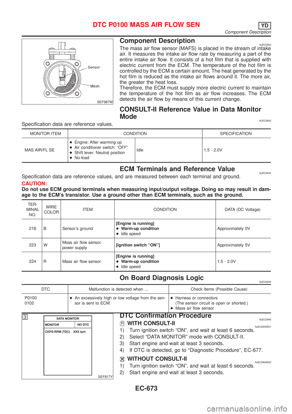
Component DescriptionNJEC0642The mass air flow sensor (MAFS) is placed in the stream of intake
air. It measures the intake air flow rate by measuring a part of the
entire intake air flow. It consists of a hot film that is supplied with
electric current from the ECM. The temperature of the hot film is
controlled by the ECM a certain amount. The heat generated by the
hot film is reduced as the intake air flows around it. The more air,
the greater the heat loss.
Therefore, the ECM must supply more electric current to maintain
the temperature of the hot film as air flow increases. The ECM
detects the air flow by means of this current change.
CONSULT-II Reference Value in Data Monitor
Mode
NJEC0643Specification data are reference values.
MONITOR ITEM CONDITION SPECIFICATION
MAS AIR/FL SE+Engine: After warming up
+Air conditioner switch: ªOFFº
+Shift lever: Neutral position
+No-loadIdle 1.5 - 2.0V
ECM Terminals and Reference ValueNJEC0644Specification data are reference values, and are measured between each terminal and ground.
CAUTION:
Do not use ECM ground terminals when measuring input/output voltage. Doing so may result in dam-
age to the ECM's transistor. Use a ground other than ECM terminals, such as the ground.
TER-
MINAL
NO.WIRE
COLORITEM CONDITION DATA (DC Voltage)
218 B Sensor's ground[Engine is running]
+Warm-up condition
+Idle speedApproximately 0V
223 WMass air flow sensor
power supply[Ignition switch ªONº]Approximately 5V
224 R Mass air flow sensor[Engine is running]
+Warm-up condition
+Idle speed1.5 - 2.0V
On Board Diagnosis LogicNJEC0645
DTC Malfunction is detected when ... Check Items (Possible Cause)
P0100
0102+An excessively high or low voltage from the sen-
sor is sent to ECM.+Harness or connectors
(The sensor circuit is open or shorted.)
+Mass air flow sensor
SEF817Y
DTC Confirmation ProcedureNJEC0646WITH CONSULT-IINJEC0646S011) Turn ignition switch ªONº, and wait at least 6 seconds.
2) Select ªDATA MONITORº mode with CONSULT-II.
3) Start engine and wait at least 3 seconds.
4) If DTC is detected, go to ªDiagnostic Procedureº, EC-677.
WITHOUT CONSULT-IINJEC0646S021) Turn ignition switch ªONº, and wait at least 6 seconds.
2) Start engine and wait at least 3 seconds.
DTC P0100 MASS AIR FLOW SENYD
Component Description
EC-673
Page 1401 of 2898
Diagnostic ProcedureNJEC0648
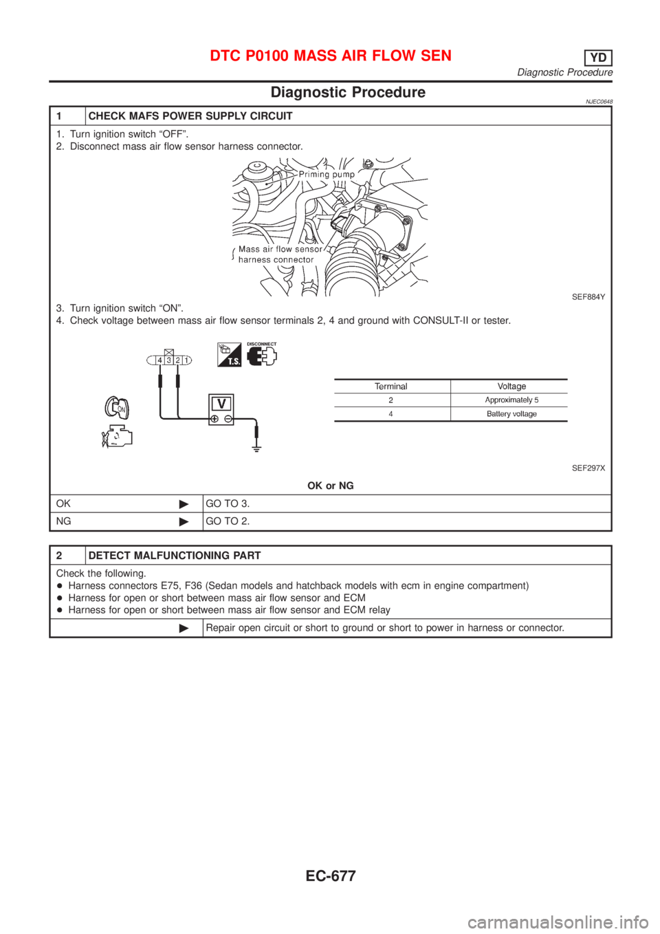
1 CHECK MAFS POWER SUPPLY CIRCUIT
1. Turn ignition switch ªOFFº.
2. Disconnect mass air flow sensor harness connector.
SEF884Y
3. Turn ignition switch ªONº.
4. Check voltage between mass air flow sensor terminals 2, 4 and ground with CONSULT-II or tester.
SEF297X
OK or NG
OK©GO TO 3.
NG©GO TO 2.
2 DETECT MALFUNCTIONING PART
Check the following.
+Harness connectors E75, F36 (Sedan models and hatchback models with ecm in engine compartment)
+Harness for open or short between mass air flow sensor and ECM
+Harness for open or short between mass air flow sensor and ECM relay
©Repair open circuit or short to ground or short to power in harness or connector.
DTC P0100 MASS AIR FLOW SENYD
Diagnostic Procedure
EC-677
Page 1402 of 2898
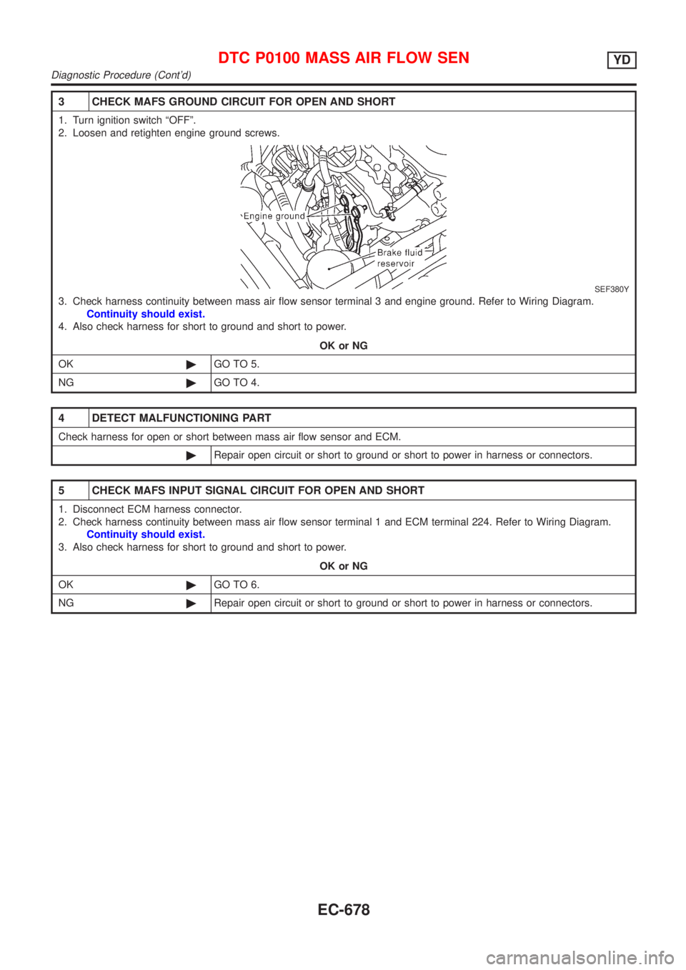
3 CHECK MAFS GROUND CIRCUIT FOR OPEN AND SHORT
1. Turn ignition switch ªOFFº.
2. Loosen and retighten engine ground screws.
SEF380Y
3. Check harness continuity between mass air flow sensor terminal 3 and engine ground. Refer to Wiring Diagram.
Continuity should exist.
4. Also check harness for short to ground and short to power.
OK or NG
OK©GO TO 5.
NG©GO TO 4.
4 DETECT MALFUNCTIONING PART
Check harness for open or short between mass air flow sensor and ECM.
©Repair open circuit or short to ground or short to power in harness or connectors.
5 CHECK MAFS INPUT SIGNAL CIRCUIT FOR OPEN AND SHORT
1. Disconnect ECM harness connector.
2. Check harness continuity between mass air flow sensor terminal 1 and ECM terminal 224. Refer to Wiring Diagram.
Continuity should exist.
3. Also check harness for short to ground and short to power.
OK or NG
OK©GO TO 6.
NG©Repair open circuit or short to ground or short to power in harness or connectors.
DTC P0100 MASS AIR FLOW SENYD
Diagnostic Procedure (Cont'd)
EC-678