lock NISSAN ALMERA 2001 Manual Online
[x] Cancel search | Manufacturer: NISSAN, Model Year: 2001, Model line: ALMERA, Model: NISSAN ALMERA 2001Pages: 2898, PDF Size: 60.76 MB
Page 514 of 2898
SRA712A
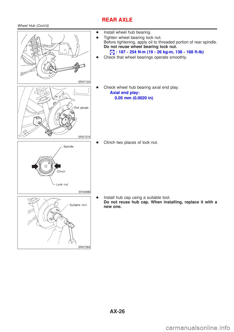
+Install wheel hub bearing.
+Tighten wheel bearing lock nut.
Before tightening, apply oil to threaded portion of rear spindle.
Do not reuse wheel bearing lock nut.
: 187 - 254 N´m (19 - 26 kg-m, 138 - 188 ft-lb)
+Check that wheel bearings operate smoothly.
SRA737A
+Check wheel hub bearing axial end play.
Axial end play:
0.05 mm (0.0020 in)
SFA599B
+Clinch two places of lock nut.
SRA738A
+Install hub cap using a suitable tool.
Do not reuse hub cap. When installing, replace it with a
new one.
REAR AXLE
Wheel Hub (Cont'd)
AX-26
Page 515 of 2898
Service Data and Specifications (SDS)
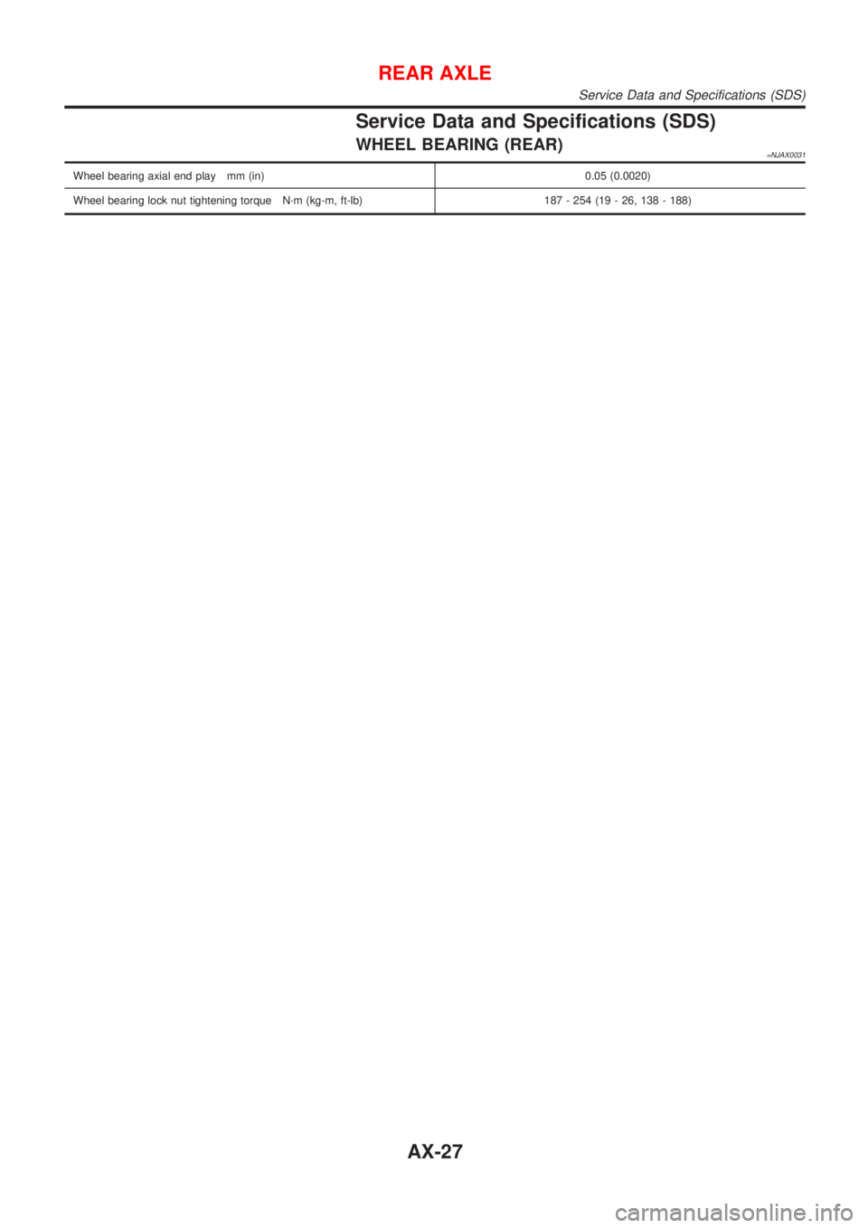
WHEEL BEARING (REAR)=NJAX0031
Wheel bearing axial end play mm (in) 0.05 (0.0020)
Wheel bearing lock nut tightening torque N´m (kg-m, ft-lb) 187 - 254 (19 - 26, 138 - 188)
REAR AXLE
Service Data and Specifications (SDS)
AX-27
Page 518 of 2898
REAR DISC BRAKE (CAM & STRUT TYPE)..............35
Component ................................................................35
Pad Replacement ......................................................35
Removal .....................................................................37
Disassembly...............................................................37
Inspection...................................................................38
CALIPER.................................................................38
ROTOR...................................................................39
Assembly ...................................................................39
Installation ..................................................................42
REAR DISC BRAKE (BALL & RAMP TYPE)..............43
Component ................................................................43
Pad Replacement ......................................................43
Removal .....................................................................45
Disassembly...............................................................45
Inspection...................................................................45
CALIPER.................................................................45
ROTOR...................................................................46
Installation ..................................................................46
PARKING BRAKE CONTROL......................................47
Components...............................................................47
Removal and Installation ...........................................47
Inspection...................................................................47
Adjustment .................................................................48
ABS
DESCRIPTION...............................................................49
Purpose......................................................................49
ABS (Anti-Lock Brake System) Operation ................49
ABS Hydraulic Circuit ................................................49
System Components .................................................50
System Description ....................................................50
SENSOR.................................................................50
CONTROL UNIT......................................................50
ABS ACTUATOR AND ELECTRIC UNIT....................50
Component Parts and Harness Connector
Location .....................................................................52
Schematic/Sedan .......................................................53
Wiring Diagram - ABS -/Sedan..................................54
Schematic/Hatchback ................................................58
Wiring Diagram - ABS -/Hatchback ...........................59
MODELS WITH SELF-DIAGNOSIS FUNCTION
(DATA LINK CONNECTOR TERMINAL NO. 9)
...........59
MODELS WITHOUT SELF-DIAGNOSIS
FUNCTION (DATA LINK CONNECTOR TERMINAL
NO. 9)
.....................................................................60
ON BOARD DIAGNOSTIC SYSTEM
DESCRIPTION...............................................................63
Self-diagnosis (Only Models with Data Link
Connector Terminal No. 9) ........................................63
FUNCTION..............................................................63
SELF-DIAGNOSIS PROCEDURE..............................63
HOW TO READ SELF-DIAGNOSTIC RESULTS
(MALFUNCTION CODES)
........................................64
HOW TO ERASE SELF-DIAGNOSTIC RESULTS
(MALFUNCTION CODES)
........................................64
CONSULT-II ...............................................................65
CONSULT-II APPLICATION TO ABS..........................65
ECU (ABS CONTROL UNIT) PART NUMBER
MODE
.....................................................................65
CONSULT-II Inspection Procedure............................65
SELF-DIAGNOSIS PROCEDURE..............................65
SELF-DIAGNOSTIC RESULTS MODE.......................67
DATA MONITOR PROCEDURE................................68
ACTIVE TEST PROCEDURE....................................69
DATA MONITOR MODE...........................................70
ACTIVE TEST MODE...............................................70
TROUBLE DIAGNOSIS - INTRODUCTION..................71
How to Perform Trouble Diagnoses for Quick
and Accurate Repair ..................................................71
INTRODUCTION......................................................71
TROUBLE DIAGNOSIS - BASIC INSPECTION...........72
Preliminary Check......................................................72
Ground Circuit Check ................................................75
ABS ACTUATOR AND ELECTRIC UNIT GROUND.....75
TROUBLE DIAGNOSIS - GENERAL
DESCRIPTION...............................................................76
Malfunction Code/Symptom Chart.............................76
MODELS WITH SELF-DIAGNOSIS FUNCTION
(DATA LINK CONNECTOR TERMINAL NO. 9)
...........76
TROUBLE DIAGNOSES FOR SELF-DIAGNOSTIC
ITEMS.............................................................................78
Wheel Sensor or Rotor ..............................................78
DIAGNOSTIC PROCEDURE.....................................78
ABS Actuator Solenoid Valve or Solenoid Valve
Relay ..........................................................................81
DIAGNOSTIC PROCEDURE.....................................81
Motor Relay or Motor.................................................84
DIAGNOSTIC PROCEDURE.....................................84
Low Voltage ...............................................................86
DIAGNOSTIC PROCEDURE.....................................86
Control Unit ................................................................88
DIAGNOSTIC PROCEDURE.....................................88
TROUBLE DIAGNOSES FOR SYMPTOMS.................89
1. ABS Works Frequently ..........................................89
2. Unexpected Pedal Action ......................................89
3. Long Stopping Distance ........................................90
4. ABS Does Not Work ..............................................91
5. Pedal Vibration and Noise.....................................92
6. ABS Warning Lamp Does Not Come On
When Ignition Switch Is Turned On...........................93
7. ABS Warning Lamp Stays On When Ignition
Switch Is Turned On ..................................................95
REMOVAL AND INSTALLATION.................................97
Wheel Sensors ..........................................................97
ABS Actuator and Electric Unit..................................98
CONTENTS(Cont'd)
BR-2
Page 526 of 2898
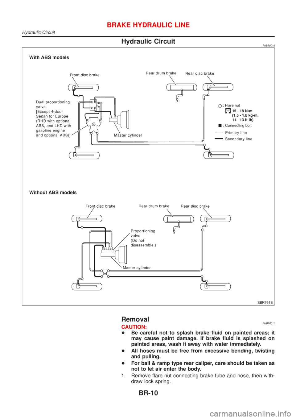
Hydraulic CircuitNJBR0010
SBR751E
RemovalNJBR0011CAUTION:
+Be careful not to splash brake fluid on painted areas; it
may cause paint damage. If brake fluid is splashed on
painted areas, wash it away with water immediately.
+All hoses must be free from excessive bending, twisting
and pulling.
+For ball & ramp type rear caliper, care should be taken as
not to let air enter the body.
1. Remove flare nut connecting brake tube and hose, then with-
draw lock spring.
BRAKE HYDRAULIC LINE
Hydraulic Circuit
BR-10
Page 529 of 2898
SBR229E
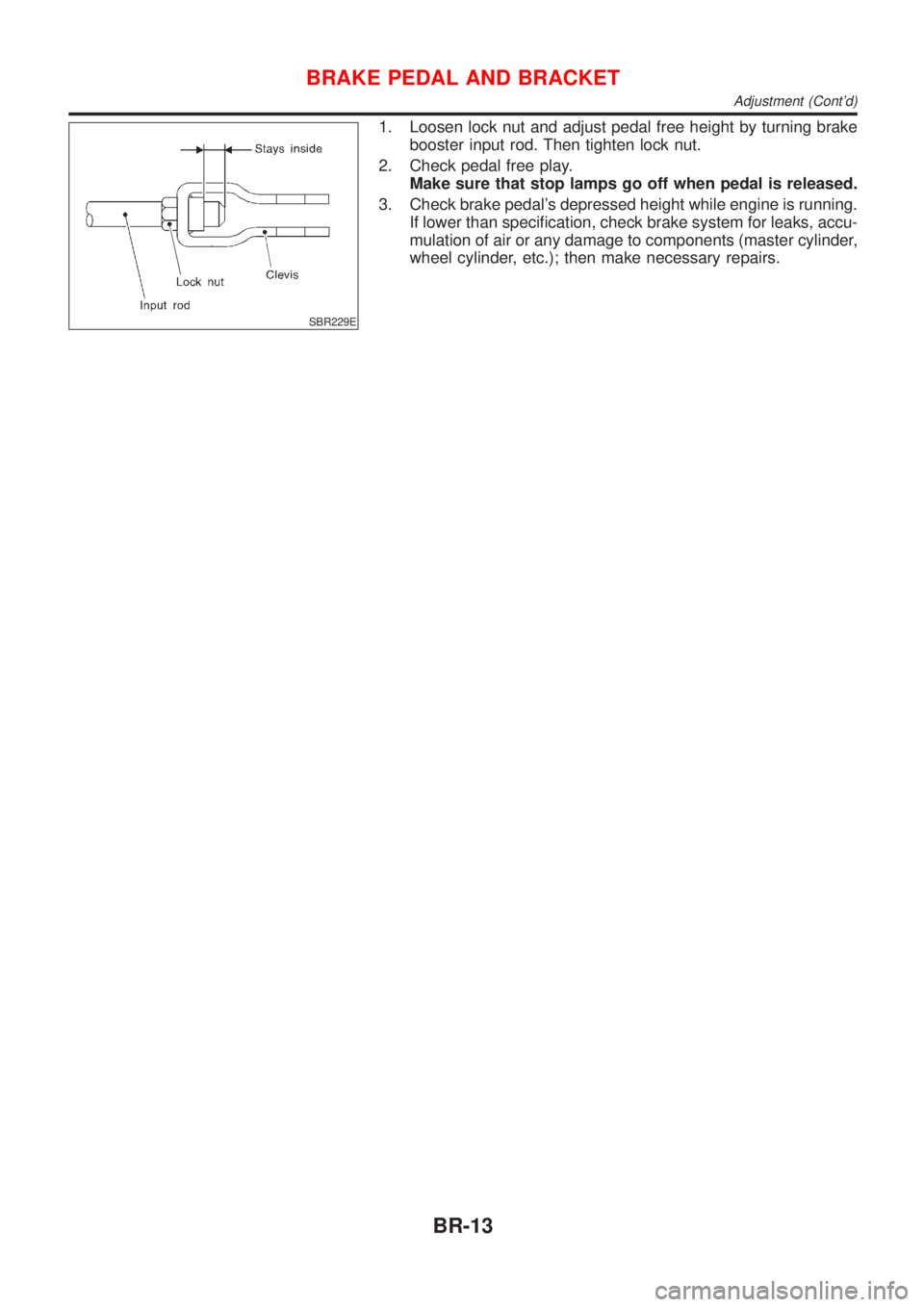
1. Loosen lock nut and adjust pedal free height by turning brake
booster input rod. Then tighten lock nut.
2. Check pedal free play.
Make sure that stop lamps go off when pedal is released.
3. Check brake pedal's depressed height while engine is running.
If lower than specification, check brake system for leaks, accu-
mulation of air or any damage to components (master cylinder,
wheel cylinder, etc.); then make necessary repairs.
BRAKE PEDAL AND BRACKET
Adjustment (Cont'd)
BR-13
Page 552 of 2898
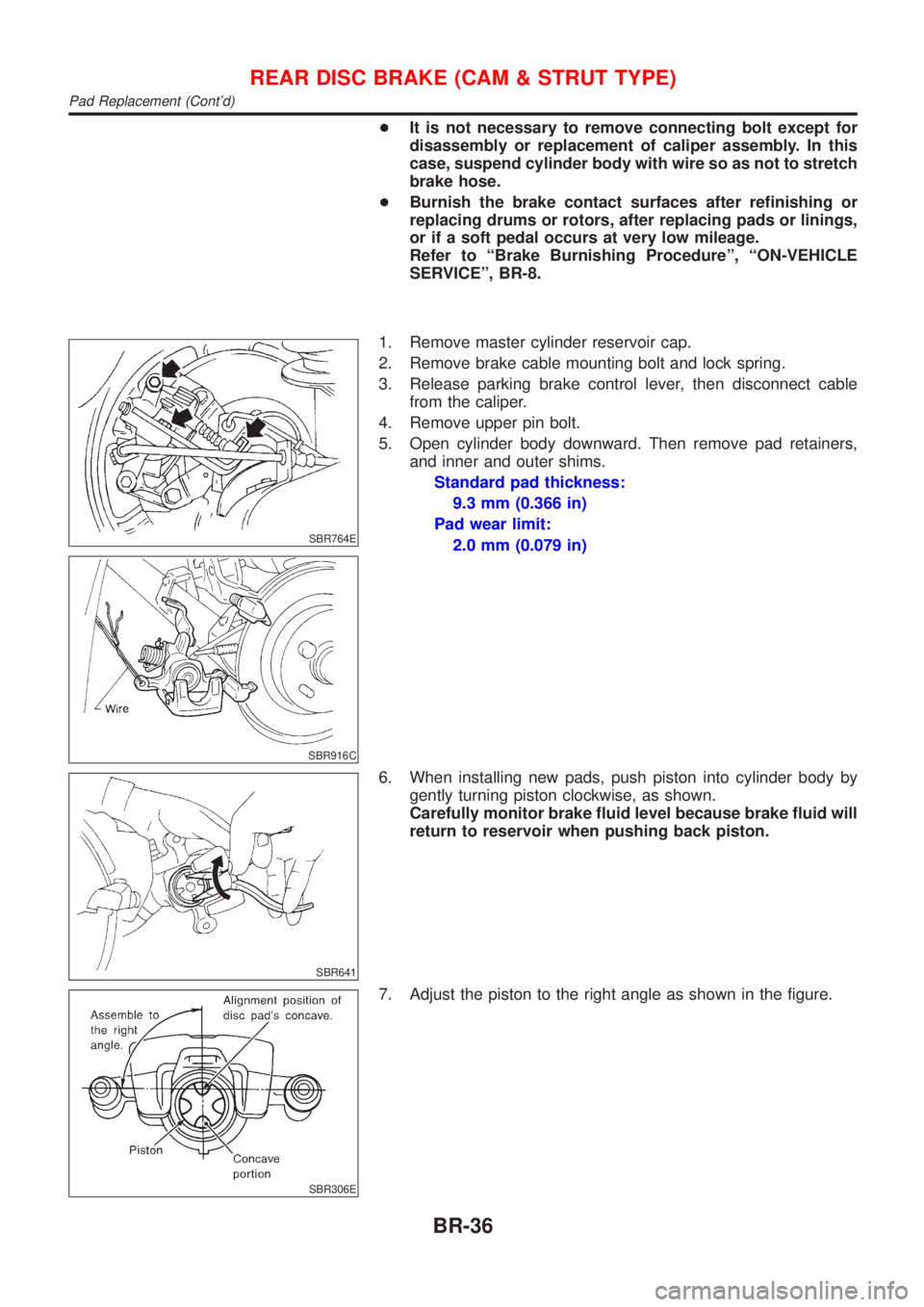
+It is not necessary to remove connecting bolt except for
disassembly or replacement of caliper assembly. In this
case, suspend cylinder body with wire so as not to stretch
brake hose.
+Burnish the brake contact surfaces after refinishing or
replacing drums or rotors, after replacing pads or linings,
or if a soft pedal occurs at very low mileage.
Refer to ªBrake Burnishing Procedureº, ªON-VEHICLE
SERVICEº, BR-8.
SBR764E
SBR916C
1. Remove master cylinder reservoir cap.
2. Remove brake cable mounting bolt and lock spring.
3. Release parking brake control lever, then disconnect cable
from the caliper.
4. Remove upper pin bolt.
5. Open cylinder body downward. Then remove pad retainers,
and inner and outer shims.
Standard pad thickness:
9.3 mm (0.366 in)
Pad wear limit:
2.0 mm (0.079 in)
SBR641
6. When installing new pads, push piston into cylinder body by
gently turning piston clockwise, as shown.
Carefully monitor brake fluid level because brake fluid will
return to reservoir when pushing back piston.
SBR306E
7. Adjust the piston to the right angle as shown in the figure.
REAR DISC BRAKE (CAM & STRUT TYPE)
Pad Replacement (Cont'd)
BR-36
Page 553 of 2898
SBR307E
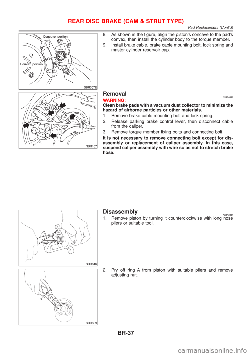
8. As shown in the figure, align the piston's concave to the pad's
convex, then install the cylinder body to the torque member.
9. Install brake cable, brake cable mounting bolt, lock spring and
master cylinder reservoir cap.
NBR167
RemovalNJBR0039WARNING:
Clean brake pads with a vacuum dust collector to minimize the
hazard of airborne particles or other materials.
1. Remove brake cable mounting bolt and lock spring.
2. Release parking brake control lever, then disconnect cable
from the caliper.
3. Remove torque member fixing bolts and connecting bolt.
It is not necessary to remove connecting bolt except for dis-
assembly or replacement of caliper assembly. In this case,
suspend caliper assembly with wire so as not to stretch brake
hose.
SBR646
DisassemblyNJBR00401. Remove piston by turning it counterclockwise with long nose
pliers or suitable tool.
SBR889
2. Pry off ring A from piston with suitable pliers and remove
adjusting nut.
REAR DISC BRAKE (CAM & STRUT TYPE)
Pad Replacement (Cont'd)
BR-37
Page 557 of 2898
SBR892
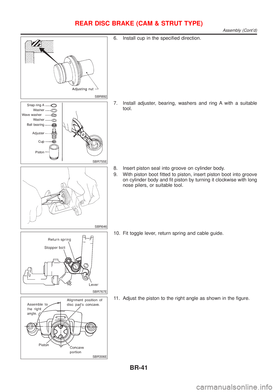
6. Install cup in the specified direction.
SBR755E
7. Install adjuster, bearing, washers and ring A with a suitable
tool.
SBR646
8. Insert piston seal into groove on cylinder body.
9. With piston boot fitted to piston, insert piston boot into groove
on cylinder body and fit piston by turning it clockwise with long
nose pilers, or suitable tool.
SBR767E
10. Fit toggle lever, return spring and cable guide.
SBR306E
11. Adjust the piston to the right angle as shown in the figure.
REAR DISC BRAKE (CAM & STRUT TYPE)
Assembly (Cont'd)
BR-41
Page 560 of 2898
NBR423
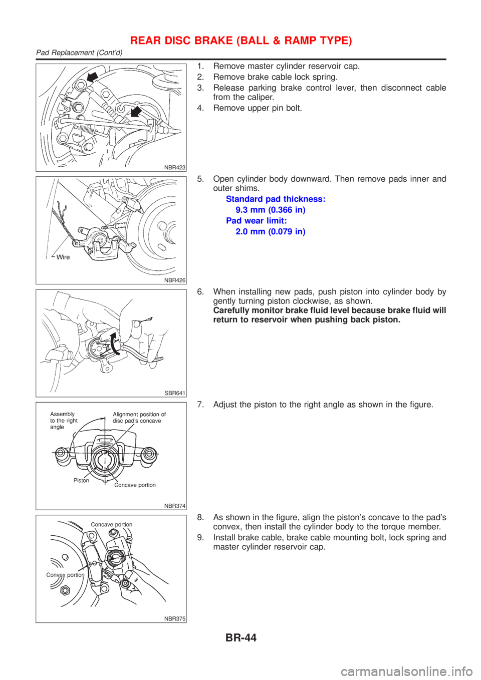
1. Remove master cylinder reservoir cap.
2. Remove brake cable lock spring.
3. Release parking brake control lever, then disconnect cable
from the caliper.
4. Remove upper pin bolt.
NBR426
5. Open cylinder body downward. Then remove pads inner and
outer shims.
Standard pad thickness:
9.3 mm (0.366 in)
Pad wear limit:
2.0 mm (0.079 in)
SBR641
6. When installing new pads, push piston into cylinder body by
gently turning piston clockwise, as shown.
Carefully monitor brake fluid level because brake fluid will
return to reservoir when pushing back piston.
NBR374
7. Adjust the piston to the right angle as shown in the figure.
NBR375
8. As shown in the figure, align the piston's concave to the pad's
convex, then install the cylinder body to the torque member.
9. Install brake cable, brake cable mounting bolt, lock spring and
master cylinder reservoir cap.
REAR DISC BRAKE (BALL & RAMP TYPE)
Pad Replacement (Cont'd)
BR-44
Page 561 of 2898
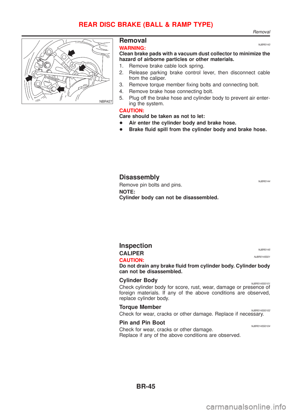
NBR427
RemovalNJBR0143WARNING:
Clean brake pads with a vacuum dust collector to minimize the
hazard of airborne particles or other materials.
1. Remove brake cable lock spring.
2. Release parking brake control lever, then disconnect cable
from the caliper.
3. Remove torque member fixing bolts and connecting bolt.
4. Remove brake hose connecting bolt.
5. Plug off the brake hose and cylinder body to prevent air enter-
ing the system.
CAUTION:
Care should be taken as not to let:
+Air enter the cylinder body and brake hose.
+Brake fluid spill from the cylinder body and brake hose.
DisassemblyNJBR0144Remove pin bolts and pins.
NOTE:
Cylinder body can not be disassembled.
InspectionNJBR0145CALIPERNJBR0145S01CAUTION:
Do not drain any brake fluid from cylinder body. Cylinder body
can not be disassembled.
Cylinder BodyNJBR0145S0101Check cylinder body for score, rust, wear, damage or presence of
foreign materials. If any of the above conditions are observed,
replace cylinder body.
Torque MemberNJBR0145S0102Check for wear, cracks or other damage. Replace if necessary.
Pin and Pin BootNJBR0145S0104Check for wear, cracks or other damage.
Replace if any of the above conditions are observed.
REAR DISC BRAKE (BALL & RAMP TYPE)
Removal
BR-45