Assembly NISSAN ALMERA 2001 Service Manual
[x] Cancel search | Manufacturer: NISSAN, Model Year: 2001, Model line: ALMERA, Model: NISSAN ALMERA 2001Pages: 2898, PDF Size: 60.76 MB
Page 5 of 2898
Component Inspection .............................................251
DTC P0755 SHIFT SOLENOID VALVE B..................252
Description ...............................................................252
Wiring Diagram - AT - SSV/B ..................................254
Diagnostic Procedure ..............................................255
Component Inspection .............................................257
DTC P1705 THROTTLE POSITION SENSOR...........258
Description ...............................................................258
Wiring Diagram - AT - TPS ......................................261
Diagnostic Procedure ..............................................263
Component Inspection .............................................267
DTC P1760 OVERRUN CLUTCH SOLENOID
VALVE..........................................................................268
Description ...............................................................268
Wiring Diagram - AT - OVRCSV..............................270
Diagnostic Procedure ..............................................271
Component Inspection .............................................273
DTC BATT/FLUID TEMP SEN (A/T FLUID TEMP
SENSOR CIRCUIT AND TCM POWER SOURCE)....274
Description ...............................................................274
Wiring Diagram - AT - BA/FTS ................................276
Diagnostic Procedure ..............................................277
Component Inspection .............................................280
DTC VHCL SPEED SEN.MTR VEHICLE SPEED
SENSOR.MTR..............................................................281
Description ...............................................................281
Wiring Diagram - AT - VSSMTR ..............................283
Diagnostic Procedure ..............................................285
DTC CONTROL UNIT (RAM), CONTROL UNIT
(ROM)...........................................................................286
Description ...............................................................286
Diagnostic Procedure ..............................................286
DTC CONTROL UNIT (EEP ROM).............................288
Description ...............................................................288
Diagnostic Procedure ..............................................289
TROUBLE DIAGNOSES FOR SYMPTOMS...............290
Wiring Diagram - AT - NONDTC/General and
Except for Euro-OBD ...............................................290
Wiring Diagram - AT - NONDTC/EURO-OBD .........292
1. O/D OFF Indicator Lamp Does Not Come On....296
2. Engine Cannot Be Started In²P²and²N²
Position ....................................................................299
3. In²P²Position, Vehicle Moves Forward Or
Backward When Pushed .........................................300
4. In²N²Position, Vehicle Moves ...........................301
5. Large Shock.²N²->²R²Position .......................303
6. Vehicle Does Not Creep Backward In²R²
Position ....................................................................305
7. Vehicle Does Not Creep Forward In²D²,²2²
Or²1²Position .........................................................3088. Vehicle Cannot Be Started From D
1................... 311
9. A/T Does Not Shift: D
1-> D2Or Does Not
Kickdown: D
4-> D2..................................................314
10. A/T Does Not Shift: D
2-> D3.............................317
11. A/T Does Not Shift: D
3-> D4.............................320
12. A/T Does Not Perform Lock-up .........................323
13. A/T Does Not Hold Lock-up Condition ..............325
14. Lock-up Is Not Released ...................................327
15. Engine Speed Does Not Return To Idle (Light
Braking D
4-> D3).....................................................328
16. Vehicle Does Not Start From D
1.......................330
17. A/T Does Not Shift: D
4-> D3, When
Overdrive Control Switch²ON²->²OFF²...............331
18. A/T Does Not Shift: D
3-> 22, When Selector
Lever²D²->²2²Position.........................................332
19. A/T Does Not Shift: 2
2-> 11, When Selector
Lever²2²->²1²Position .........................................333
20. Vehicle Does Not Decelerate By Engine
Brake........................................................................334
21. TCM Self-diagnosis Does Not Activate (PNP,
Overdrive Control and Throttle Position Switches
Circuit Checks) ........................................................334
A/T SHIFT LOCK SYSTEM.........................................343
Description ...............................................................343
Shift Lock System Electrical Parts Location............343
Wiring Diagram - SHIFT -........................................344
Diagnostic Procedure ..............................................345
KEY INTERLOCK CABLE..........................................349
Components.............................................................349
Removal ...................................................................349
Installation ................................................................350
ON-VEHICLE SERVICE..............................................351
Control Valve Assembly and Accumulators .............351
Control Cable Adjustment ........................................352
Park/Neutral Position (PNP) Switch Adjustment .....352
Differential Side Oil Seal Replacement ...................353
Revolution Sensor Replacement .............................353
REMOVAL AND INSTALLATION...............................354
Removal ...................................................................354
Installation ................................................................355
OVERHAUL.................................................................357
Components-1 3AX00, 3AX01, 3AX19, 3AX63
and 3AX64 models ..................................................357
Components-1 3AX10 and 3AX18 models .............358
Components-2 3AX00, 3AX01, 3AX19, 3AX63
and 3AX64 models ..................................................359
Components-2 3AX10 and 3AX18 models .............360
Components-3 3AX00, 3AX01, 3AX19, 3AX63
and 3AX64 models ..................................................361
Components-3 3AX10 and 3AX18 models .............362
Oil Channel ..............................................................363
CONTENTS(Cont'd)
AT-3
Page 6 of 2898
Locations of Adjusting Shims, Needle Bearings,
Thrust Washers and Snap Rings - 3AX00, 01,
19, 63 and 64 models..............................................364
Locations of Adjusting Shims, Needle Bearings,
Thrust Washers and Snap Rings - 3AX10 and
3AX18 models .........................................................365
DISASSEMBLY............................................................366
REPAIR FOR COMPONENT PARTS.........................381
Manual Shaft............................................................381
Oil Pump ..................................................................384
Control Valve Assembly ...........................................388
Control Valve Upper Body .......................................397
Control Valve Lower Body .......................................401
Reverse Clutch ........................................................403
High Clutch ..............................................................407
Forward Clutch and Overrun Clutch........................412
Low & Reverse Brake..............................................419
Rear Internal Gear, Forward Clutch Hub and
Overrun Clutch Hub .................................................423
O/Shaft, O/Gear, I/Gear, R/Pinion Gear and B/
Retainer - 3AX00, 01, 19, 63 and 64 models .........427
Output Shaft, Idler Gear, Reduction Pinion Gear
and Bearing Retainer - 3AX10 and 3AX18
models .....................................................................432
Band Servo Piston Assembly ..................................437
Final Drive................................................................442
ASSEMBLY..................................................................446
Assembly (1) ............................................................446
Adjustment (1) .........................................................447
Assembly (2) ............................................................455Adjustment (2) .........................................................459
Assembly (3) ............................................................462
Assembly (4) ............................................................465
SERVICE DATA AND SPECIFICATIONS (SDS).......470
General Specifications .............................................470
Shift Schedule..........................................................470
Stall Revolution ........................................................473
Line Pressure...........................................................473
Control Valves..........................................................474
Clutch and Brakes ...................................................474
Clutch and Brake Return Springs............................477
Oil Pump ..................................................................477
Input Shaft ...............................................................478
Planetary Carrier......................................................478
Final Drive................................................................478
Reduction Pinion Gear ............................................480
Output Shaft - 3AX00, 3AX01, 3AX19, 3AX63
and 3AX64 models ..................................................481
Output Shaft - 3AX10 and 3AX18 models ..............483
Bearing Retainer ......................................................484
Total End Play..........................................................484
Reverse Clutch End Play ........................................484
Accumulator .............................................................484
Band Servo ..............................................................485
Removal and Installation .........................................485
Shift Solenoid Valves ...............................................485
Resistance ...............................................................485
ATF Temp. Sensor ...................................................485
Revolution Sensor ...................................................485
Dropping Resistor ....................................................485
CONTENTS(Cont'd)
AT-4
Page 10 of 2898
AAT470A
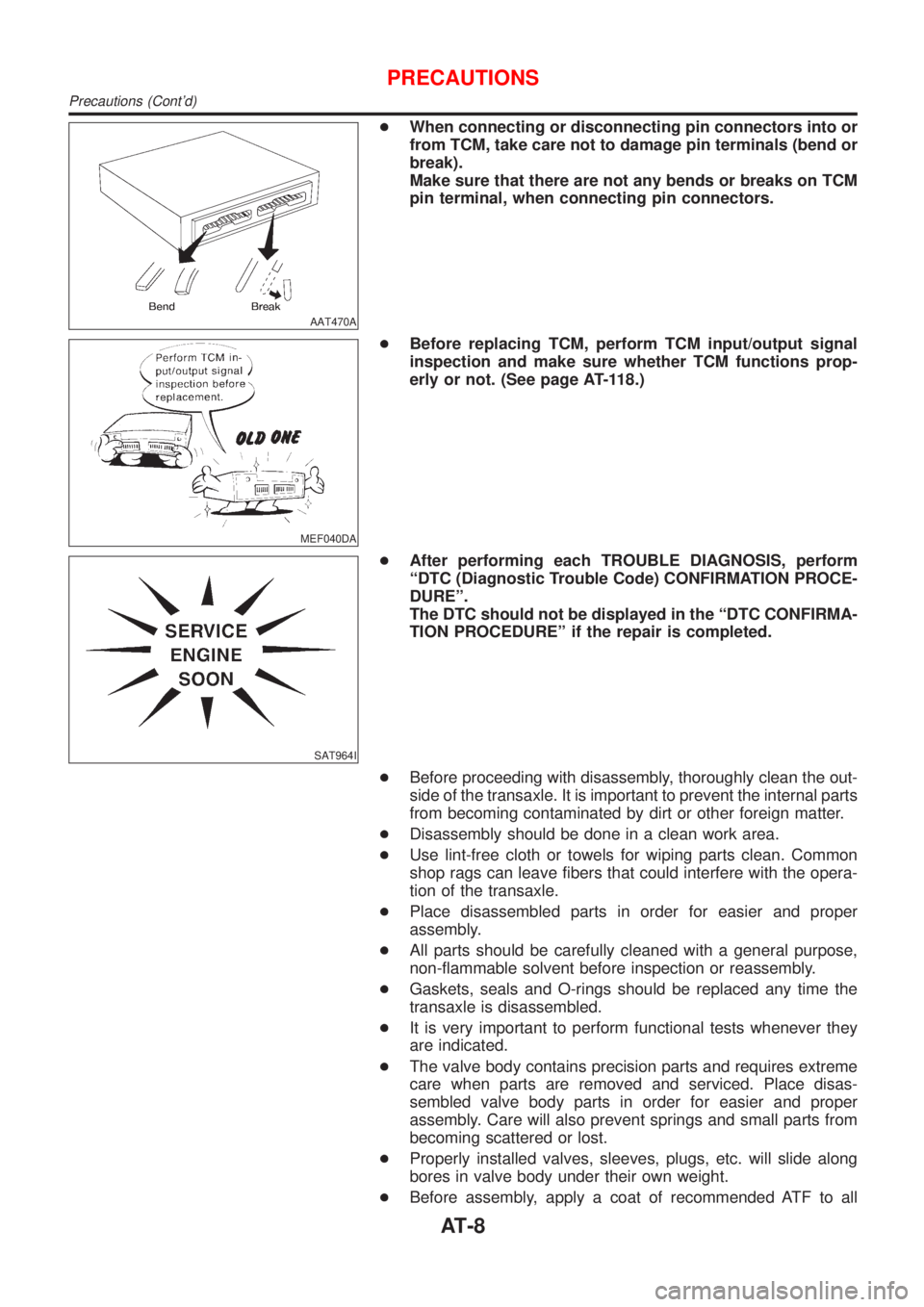
+When connecting or disconnecting pin connectors into or
from TCM, take care not to damage pin terminals (bend or
break).
Make sure that there are not any bends or breaks on TCM
pin terminal, when connecting pin connectors.
MEF040DA
+Before replacing TCM, perform TCM input/output signal
inspection and make sure whether TCM functions prop-
erly or not. (See page AT-118.)
SAT964I
+After performing each TROUBLE DIAGNOSIS, perform
ªDTC (Diagnostic Trouble Code) CONFIRMATION PROCE-
DUREº.
The DTC should not be displayed in the ªDTC CONFIRMA-
TION PROCEDUREº if the repair is completed.
+Before proceeding with disassembly, thoroughly clean the out-
side of the transaxle. It is important to prevent the internal parts
from becoming contaminated by dirt or other foreign matter.
+Disassembly should be done in a clean work area.
+Use lint-free cloth or towels for wiping parts clean. Common
shop rags can leave fibers that could interfere with the opera-
tion of the transaxle.
+Place disassembled parts in order for easier and proper
assembly.
+All parts should be carefully cleaned with a general purpose,
non-flammable solvent before inspection or reassembly.
+Gaskets, seals and O-rings should be replaced any time the
transaxle is disassembled.
+It is very important to perform functional tests whenever they
are indicated.
+The valve body contains precision parts and requires extreme
care when parts are removed and serviced. Place disas-
sembled valve body parts in order for easier and proper
assembly. Care will also prevent springs and small parts from
becoming scattered or lost.
+Properly installed valves, sleeves, plugs, etc. will slide along
bores in valve body under their own weight.
+Before assembly, apply a coat of recommended ATF to all
PRECAUTIONS
Precautions (Cont'd)
AT-8
Page 11 of 2898
parts. Apply petroleum jelly to protect O-rings and seals, or
hold bearings and washers in place during assembly. Do not
use grease.
+Extreme care should be taken to avoid damage to O-rings,
seals and gaskets when assembling.
+After overhaul, refill the transaxle with new ATF.
+When the A/T drain plug is removed, only some of the fluid is
drained. Old A/T fluid will remain in torque converter and ATF
cooling system.
Always follow the procedures under ªChanging A/T Fluidº in the
AT section when changing A/T fluid. Refer to ªChanging A/T
Fluidº, AT-15.
Service Notice or PrecautionsNJAT0247FAIL-SAFENJAT0247S01The TCM has an electronic Fail-Safe (limp home mode). This allows the vehicle to be driven even if a major
electrical input/output device circuit is damaged.
Under Fail-Safe, the vehicle always runs in third gear, even with a shift lever position of ª1º, ª2º or ªDº. The
customer may complain of sluggish or poor acceleration.
When the ignition key is turned ªONº following Fail-Safe operation, O/D OFF indicator lamp blinks for about
8 seconds. (For GENERAL AND EXCEPT FOR EURO-OBD; ªSELF-DIAGNOSTIC PROCEDURE (WITHOUT
CONSULT-II)º, refer to AT-44 and for EURO-OBD; ªTCM SELF-DIAGNOSTIC PROCEDURE (No Tools)º, refer
to AT-63.)
Fail-Safe may occur without electrical circuit damage if the vehicle is driven under extreme conditions (such
as excessive wheel spin followed by sudden braking). To recover normal shift pattern, turn the ignition key
ªOFFº for 5 seconds, then ªONº.
The blinking of the O/D OFF indicator lamp for about 8 seconds will appear only once and be cleared. The
customer may resume normal driving conditions.
Always follow the ªWORK FLOWº [Refer to AT-73 (General and except for Euro-OBD), AT-78 (EURO-OBD).]
The SELF-DIAGNOSIS results will be as follows:
The first SELF-DIAGNOSIS will indicate damage to the vehicle speed sensor or the revolution sensor.
During the next SELF-DIAGNOSIS, performed after checking the sensor, no damages will be indicated.
TORQUE CONVERTER SERVICENJAT0247S02The torque converter should be replaced under any of the following conditions:
+External leaks in the hub weld area.
+Converter hub is scored or damaged.
+Converter pilot is broken, damaged or fits poorly into crankshaft.
+Steel particles are found after flushing the cooler and cooler lines.
+Pump is damaged or steel particles are found in the converter.
+Vehicle has TCC shudder and/or no TCC apply. Replace only after all hydraulic and electrical diagnoses
have been made. (Converter clutch material may be glazed.)
+Converter is contaminated with engine coolant containing antifreeze.
+Internal failure of stator roller clutch.
+Heavy clutch debris due to overheating (blue converter).
+Steel particles or clutch lining material found in fluid filter or on magnet when no internal parts in unit are
worn or damaged Ð indicates that lining material came from converter.
PRECAUTIONS
Precautions (Cont'd)
AT-9
Page 107 of 2898
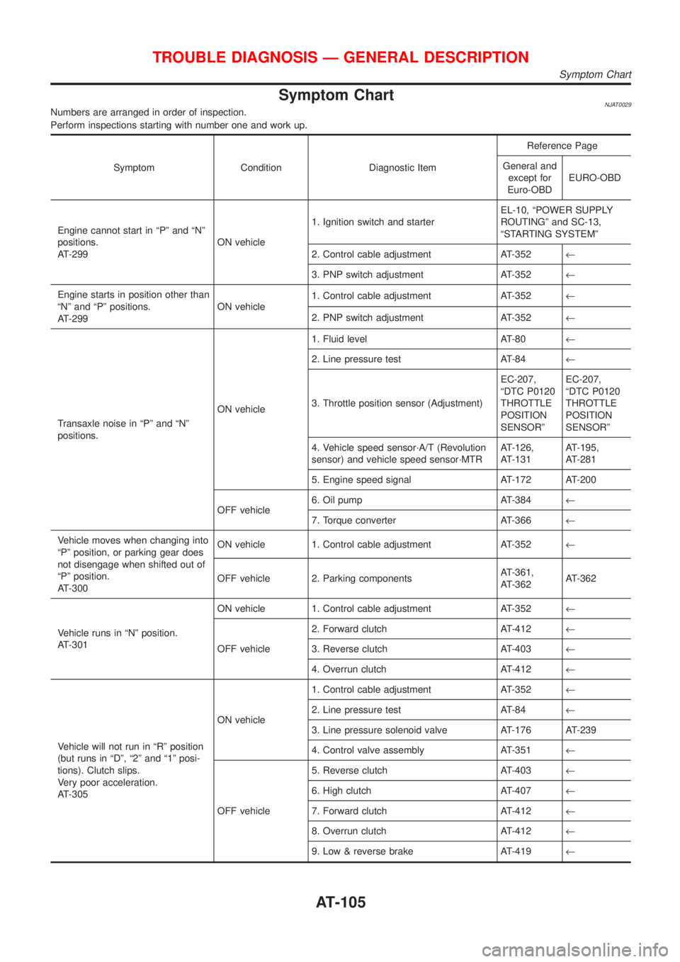
Symptom ChartNJAT0029Numbers are arranged in order of inspection.
Perform inspections starting with number one and work up.
Symptom Condition Diagnostic ItemReference Page
General and
except for
Euro-OBDEURO-OBD
Engine cannot start in ªPº and ªNº
positions.
AT-299ON vehicle1. Ignition switch and starterEL-10, ªPOWER SUPPLY
ROUTINGº and SC-13,
ªSTARTING SYSTEMº
2. Control cable adjustment AT-352¬
3. PNP switch adjustment AT-352¬
Engine starts in position other than
ªNº and ªPº positions.
AT-299ON vehicle1. Control cable adjustment AT-352¬
2. PNP switch adjustment AT-352¬
Transaxle noise in ªPº and ªNº
positions.ON vehicle1. Fluid level AT-80¬
2. Line pressure test AT-84¬
3. Throttle position sensor (Adjustment)EC-207,
ªDTC P0120
THROTTLE
POSITION
SENSORºEC-207,
ªDTC P0120
THROTTLE
POSITION
SENSORº
4. Vehicle speed sensor´A/T (Revolution
sensor) and vehicle speed sensor´MTRAT-126,
AT-131AT-195,
AT-281
5. Engine speed signal AT-172 AT-200
OFF vehicle6. Oil pump AT-384¬
7. Torque converter AT-366¬
Vehicle moves when changing into
ªPº position, or parking gear does
not disengage when shifted out of
ªPº position.
AT-300ON vehicle 1. Control cable adjustment AT-352¬
OFF vehicle 2. Parking componentsAT-361,
AT-362AT-362
Vehicle runs in ªNº position.
AT-301ON vehicle 1. Control cable adjustment AT-352¬
OFF vehicle2. Forward clutch AT-412¬
3. Reverse clutch AT-403¬
4. Overrun clutch AT-412¬
Vehicle will not run in ªRº position
(but runs in ªDº, ª2º and ª1º posi-
tions). Clutch slips.
Very poor acceleration.
AT-305ON vehicle1. Control cable adjustment AT-352¬
2. Line pressure test AT-84¬
3. Line pressure solenoid valve AT-176 AT-239
4. Control valve assembly AT-351¬
OFF vehicle5. Reverse clutch AT-403¬
6. High clutch AT-407¬
7. Forward clutch AT-412¬
8. Overrun clutch AT-412¬
9. Low & reverse brake AT-419¬
TROUBLE DIAGNOSIS Ð GENERAL DESCRIPTION
Symptom Chart
AT-105
Page 108 of 2898
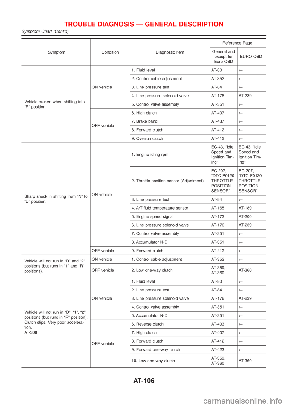
Symptom Condition Diagnostic ItemReference Page
General and
except for
Euro-OBDEURO-OBD
Vehicle braked when shifting into
ªRº position.ON vehicle1. Fluid level AT-80¬
2. Control cable adjustment AT-352¬
3. Line pressure test AT-84¬
4. Line pressure solenoid valve AT-176 AT-239
5. Control valve assembly AT-351¬
OFF vehicle6. High clutch AT-407¬
7. Brake band AT-437¬
8. Forward clutch AT-412¬
9. Overrun clutch AT-412¬
Sharp shock in shifting from ªNº to
ªDº position.ON vehicle1. Engine idling rpmEC-43, ªIdle
Speed and
Ignition Tim-
ingºEC-43, ªIdle
Speed and
Ignition Tim-
ingº
2. Throttle position sensor (Adjustment)EC-207,
ªDTC P0120
THROTTLE
POSITION
SENSORºEC-207,
ªDTC P0120
THROTTLE
POSITION
SENSORº
3. Line pressure test AT-84¬
4. A/T fluid temperature sensor AT-165 AT-189
5. Engine speed signal AT-172 AT-200
6. Line pressure solenoid valve AT-176 AT-239
7. Control valve assembly AT-351¬
8. Accumulator N-D AT-351¬
OFF vehicle 9. Forward clutch AT-412¬
Vehicle will not run in ªDº and ª2º
positions (but runs in ª1º and ªRº
positions).ON vehicle 1. Control cable adjustment AT-352¬
OFF vehicle 2. Low one-way clutchAT-359,
AT-360AT-360
Vehicle will not run in ªDº, ª1º, ª2º
positions (but runs in ªRº position).
Clutch slips. Very poor accelera-
tion.
AT-308ON vehicle1. Fluid level AT-80¬
2. Line pressure test AT-84¬
3. Line pressure solenoid valve AT-176 AT-239
4. Control valve assembly AT-351¬
5. Accumulator N-D AT-351¬
OFF vehicle6. Reverse clutch AT-403¬
7. High clutch AT-407¬
8. Forward clutch AT-412¬
9. Forward one-way clutch AT-423¬
10. Low one-way clutchAT-359,
AT-360AT-360
TROUBLE DIAGNOSIS Ð GENERAL DESCRIPTION
Symptom Chart (Cont'd)
AT-106
Page 109 of 2898
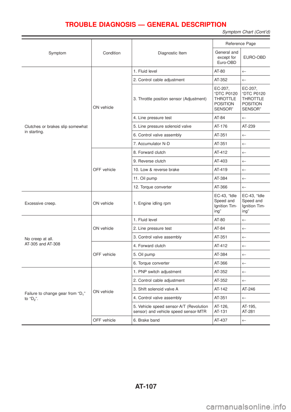
Symptom Condition Diagnostic ItemReference Page
General and
except for
Euro-OBDEURO-OBD
Clutches or brakes slip somewhat
in starting.ON vehicle1. Fluid level AT-80¬
2. Control cable adjustment AT-352¬
3. Throttle position sensor (Adjustment)EC-207,
ªDTC P0120
THROTTLE
POSITION
SENSORºEC-207,
ªDTC P0120
THROTTLE
POSITION
SENSORº
4. Line pressure test AT-84¬
5. Line pressure solenoid valve AT-176 AT-239
6. Control valve assembly AT-351¬
7. Accumulator N-D AT-351¬
OFF vehicle8. Forward clutch AT-412¬
9. Reverse clutch AT-403¬
10. Low & reverse brake AT-419¬
11. Oil pump AT-384¬
12. Torque converter AT-366¬
Excessive creep. ON vehicle 1. Engine idling rpmEC-43, ªIdle
Speed and
Ignition Tim-
ingºEC-43, ªIdle
Speed and
Ignition Tim-
ingº
No creep at all.
AT-305 and AT-308ON vehicle1. Fluid level AT-80¬
2. Line pressure test AT-84¬
3. Control valve assembly AT-351¬
OFF vehicle4. Forward clutch AT-412¬
5. Oil pump AT-384¬
6. Torque converter AT-366¬
Failure to change gear from ªD
1º
to ªD
2º.ON vehicle1. PNP switch adjustment AT-352¬
2. Control cable adjustment AT-352¬
3. Shift solenoid valve A AT-142 AT-246
4. Control valve assembly AT-351¬
5. Vehicle speed sensor´A/T (Revolution
sensor) and vehicle speed sensor´MTRAT-126,
AT-131AT-195,
AT-281
OFF vehicle 6. Brake band AT-437¬
TROUBLE DIAGNOSIS Ð GENERAL DESCRIPTION
Symptom Chart (Cont'd)
AT-107
Page 110 of 2898
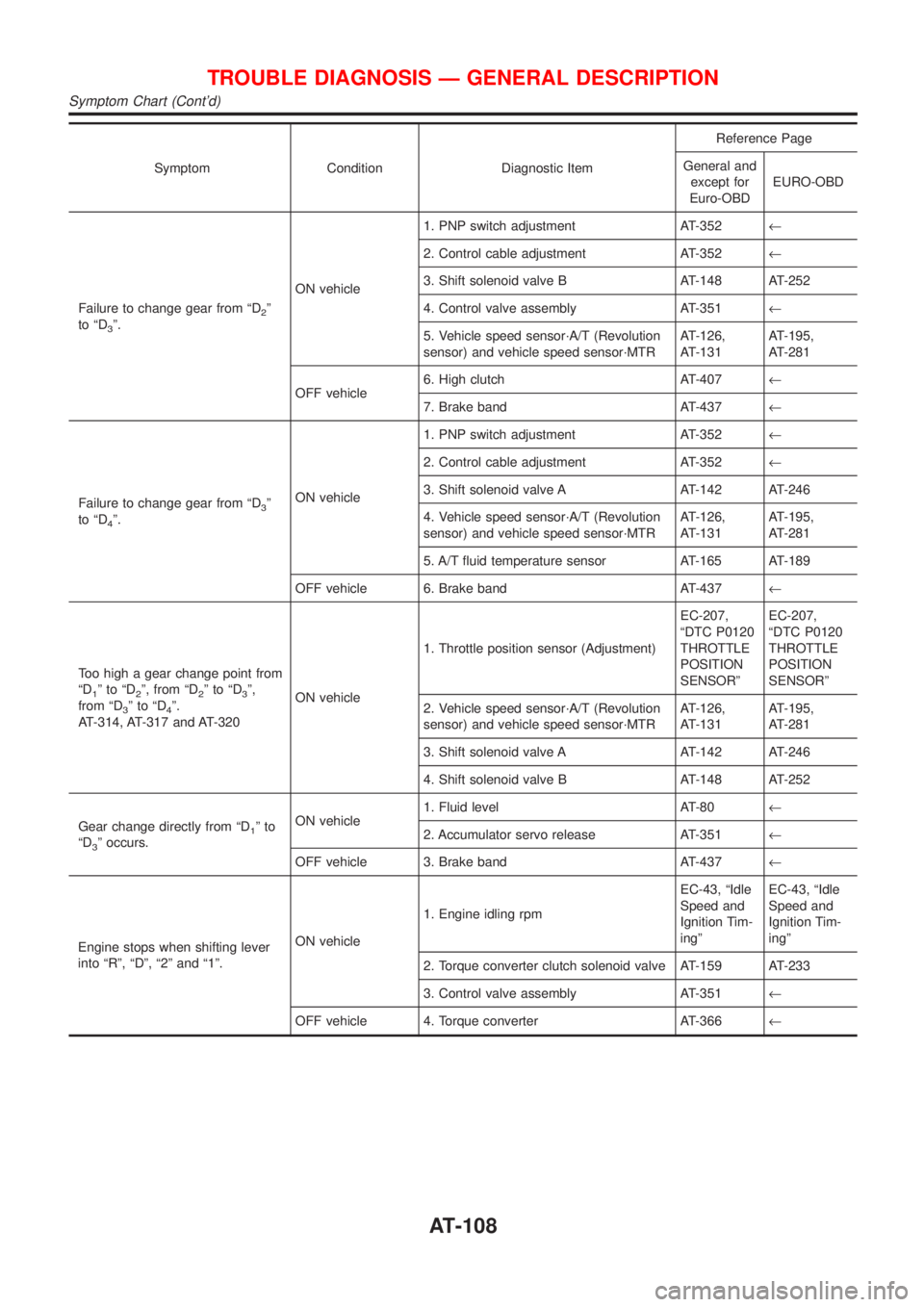
Symptom Condition Diagnostic ItemReference Page
General and
except for
Euro-OBDEURO-OBD
Failure to change gear from ªD
2º
to ªD
3º.ON vehicle1. PNP switch adjustment AT-352¬
2. Control cable adjustment AT-352¬
3. Shift solenoid valve B AT-148 AT-252
4. Control valve assembly AT-351¬
5. Vehicle speed sensor´A/T (Revolution
sensor) and vehicle speed sensor´MTRAT-126,
AT-131AT-195,
AT-281
OFF vehicle6. High clutch AT-407¬
7. Brake band AT-437¬
Failure to change gear from ªD
3º
to ªD
4º.ON vehicle1. PNP switch adjustment AT-352¬
2. Control cable adjustment AT-352¬
3. Shift solenoid valve A AT-142 AT-246
4. Vehicle speed sensor´A/T (Revolution
sensor) and vehicle speed sensor´MTRAT-126,
AT-131AT-195,
AT-281
5. A/T fluid temperature sensor AT-165 AT-189
OFF vehicle 6. Brake band AT-437¬
Too high a gear change point from
ªD
1ºtoªD2º, from ªD2ºtoªD3º,
from ªD
3ºtoªD4º.
AT-314, AT-317 and AT-320ON vehicle1. Throttle position sensor (Adjustment)EC-207,
ªDTC P0120
THROTTLE
POSITION
SENSORºEC-207,
ªDTC P0120
THROTTLE
POSITION
SENSORº
2. Vehicle speed sensor´A/T (Revolution
sensor) and vehicle speed sensor´MTRAT-126,
AT-131AT-195,
AT-281
3. Shift solenoid valve A AT-142 AT-246
4. Shift solenoid valve B AT-148 AT-252
Gear change directly from ªD
1ºto
ªD
3º occurs.ON vehicle1. Fluid level AT-80¬
2. Accumulator servo release AT-351¬
OFF vehicle 3. Brake band AT-437¬
Engine stops when shifting lever
into ªRº, ªDº, ª2º and ª1º.ON vehicle1. Engine idling rpmEC-43, ªIdle
Speed and
Ignition Tim-
ingºEC-43, ªIdle
Speed and
Ignition Tim-
ingº
2. Torque converter clutch solenoid valve AT-159 AT-233
3. Control valve assembly AT-351¬
OFF vehicle 4. Torque converter AT-366¬
TROUBLE DIAGNOSIS Ð GENERAL DESCRIPTION
Symptom Chart (Cont'd)
AT-108
Page 111 of 2898
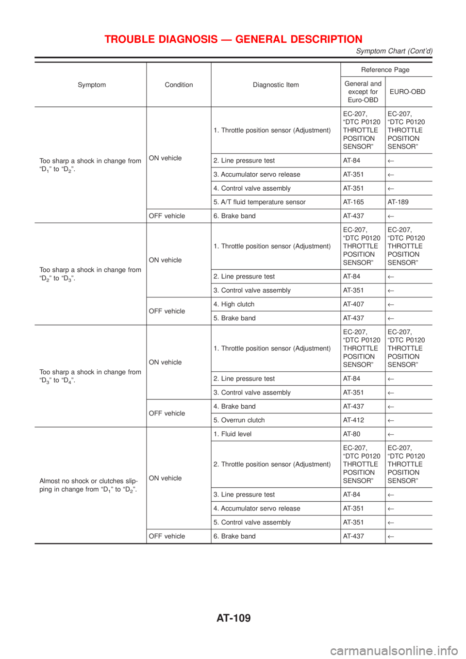
Symptom Condition Diagnostic ItemReference Page
General and
except for
Euro-OBDEURO-OBD
Too sharp a shock in change from
ªD
1ºtoªD2º.ON vehicle1. Throttle position sensor (Adjustment)EC-207,
ªDTC P0120
THROTTLE
POSITION
SENSORºEC-207,
ªDTC P0120
THROTTLE
POSITION
SENSORº
2. Line pressure test AT-84¬
3. Accumulator servo release AT-351¬
4. Control valve assembly AT-351¬
5. A/T fluid temperature sensor AT-165 AT-189
OFF vehicle 6. Brake band AT-437¬
Too sharp a shock in change from
ªD
2ºtoªD3º.ON vehicle1. Throttle position sensor (Adjustment)EC-207,
ªDTC P0120
THROTTLE
POSITION
SENSORºEC-207,
ªDTC P0120
THROTTLE
POSITION
SENSORº
2. Line pressure test AT-84¬
3. Control valve assembly AT-351¬
OFF vehicle4. High clutch AT-407¬
5. Brake band AT-437¬
Too sharp a shock in change from
ªD
3ºtoªD4º.ON vehicle1. Throttle position sensor (Adjustment)EC-207,
ªDTC P0120
THROTTLE
POSITION
SENSORºEC-207,
ªDTC P0120
THROTTLE
POSITION
SENSORº
2. Line pressure test AT-84¬
3. Control valve assembly AT-351¬
OFF vehicle4. Brake band AT-437¬
5. Overrun clutch AT-412¬
Almost no shock or clutches slip-
ping in change from ªD
1ºtoªD2º.ON vehicle1. Fluid level AT-80¬
2. Throttle position sensor (Adjustment)EC-207,
ªDTC P0120
THROTTLE
POSITION
SENSORºEC-207,
ªDTC P0120
THROTTLE
POSITION
SENSORº
3. Line pressure test AT-84¬
4. Accumulator servo release AT-351¬
5. Control valve assembly AT-351¬
OFF vehicle 6. Brake band AT-437¬
TROUBLE DIAGNOSIS Ð GENERAL DESCRIPTION
Symptom Chart (Cont'd)
AT-109
Page 112 of 2898
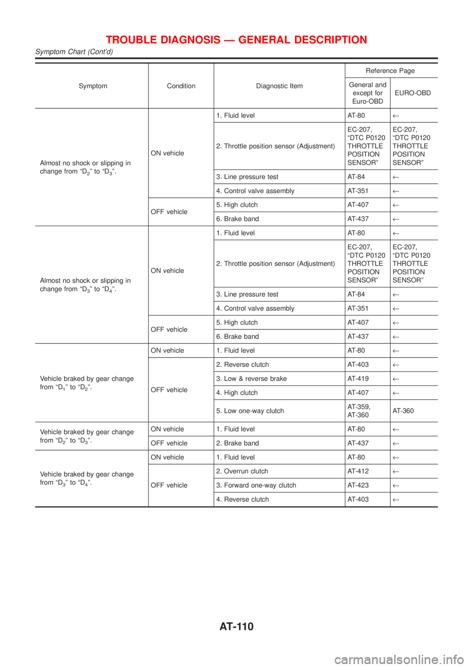
Symptom Condition Diagnostic ItemReference Page
General and
except for
Euro-OBDEURO-OBD
Almost no shock or slipping in
change from ªD
2ºtoªD3º.ON vehicle1. Fluid level AT-80¬
2. Throttle position sensor (Adjustment)EC-207,
ªDTC P0120
THROTTLE
POSITION
SENSORºEC-207,
ªDTC P0120
THROTTLE
POSITION
SENSORº
3. Line pressure test AT-84¬
4. Control valve assembly AT-351¬
OFF vehicle5. High clutch AT-407¬
6. Brake band AT-437¬
Almost no shock or slipping in
change from ªD
3ºtoªD4º.ON vehicle1. Fluid level AT-80¬
2. Throttle position sensor (Adjustment)EC-207,
ªDTC P0120
THROTTLE
POSITION
SENSORºEC-207,
ªDTC P0120
THROTTLE
POSITION
SENSORº
3. Line pressure test AT-84¬
4. Control valve assembly AT-351¬
OFF vehicle5. High clutch AT-407¬
6. Brake band AT-437¬
Vehicle braked by gear change
from ªD
1ºtoªD2º.ON vehicle 1. Fluid level AT-80¬
OFF vehicle2. Reverse clutch AT-403¬
3. Low & reverse brake AT-419¬
4. High clutch AT-407¬
5. Low one-way clutchAT-359,
AT-360AT-360
Vehicle braked by gear change
from ªD
2ºtoªD3º.ON vehicle 1. Fluid level AT-80¬
OFF vehicle 2. Brake band AT-437¬
Vehicle braked by gear change
from ªD
3ºtoªD4º.ON vehicle 1. Fluid level AT-80¬
OFF vehicle2. Overrun clutch AT-412¬
3. Forward one-way clutch AT-423¬
4. Reverse clutch AT-403¬
TROUBLE DIAGNOSIS Ð GENERAL DESCRIPTION
Symptom Chart (Cont'd)
AT-110