NISSAN ALMERA N15 1995 Service Manual
Manufacturer: NISSAN, Model Year: 1995, Model line: ALMERA N15, Model: NISSAN ALMERA N15 1995Pages: 1701, PDF Size: 82.27 MB
Page 1691 of 1701
POWERSTEERING GEARANDLINKAGE (ModelPR24AC)
Assembly (Cont'd)
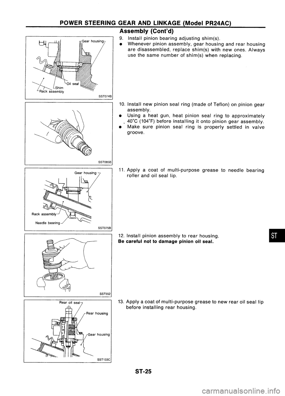
9. Install pinionbearing adjusting shim(s).
• Whenever pinionassembly, gearhousing andrear housing
are disassembled, replaceshim(s)withnewones. Always
use thesame number ofshim(s) whenreplacing.
SST074B
10.Install newpinion sealring(made ofTeflon) onpinion gear
assembly.
• Using aheat gun, heatpinion sealringtoapproximately
. 40°C (104°F) beforeinstalling itonto pinion gearassembly.
• Make surepinion sealringisproperly settledinvalve
groove.
SST085B
11.Apply acoat ofmulti-purpose greasetoneedle bearing
roller andoilseal lip.
SST075B
12.Install pinionassembly torear housing.
Be careful nottodamage pinionoilseal.
SST552
•
13. Apply acoat ofmulti-purpose greasetonew rearoilseal lip
before installing rearhousing.
Gear housing
SST133C ST-25
Page 1692 of 1701
POWERSTEERING GEARANDLINKAGE (ModelPR24AC)
Assembly (Cont'd)
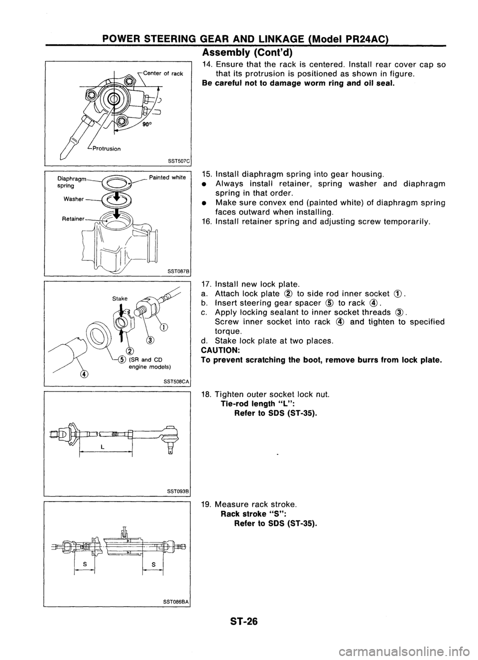
14. Ensure thattherack iscentered. Installrearcover capso
that itsprotrusion ispositioned asshown infigure.
Be careful nottodamage wormringandoilseal.
88T507C
15.Install diaphragm springintogear housing.
• Always installretainer, springwasher anddiaphragm
spring inthat order.
• Make sureconvex end(painted white)ofdiaphragm spring
faces outward wheninstalling.
16. Install retainer springandadjusting screwtemporarily.
88T0878
17.Install newlockplate.
a. Attach lockplate
@
toside rodinner socket
(!).
b. Insert steering gearspacer
CID
torack
@.
c. Apply locking sealant toinner socket threads
CID.
Screw innersocket intorack
@
and tighten tospecified
torque.
d. Stake lockplate attwo places.
CAUTION:
To prevent scratching theboot, remove burrsfromlockplate.
18. Tighten outersocket locknut.
Tie-rod length
"L":
Refer toSOS (ST-35).
88T0938
19.Measure rackstroke.
Rack stroke
"5":
Refer to50S (ST-35).
s
88T0868A ST-26
Page 1693 of 1701
POWERSTEERING GEARANDLINKAGE (ModelPR24AC)
Assembly (Cont'd)
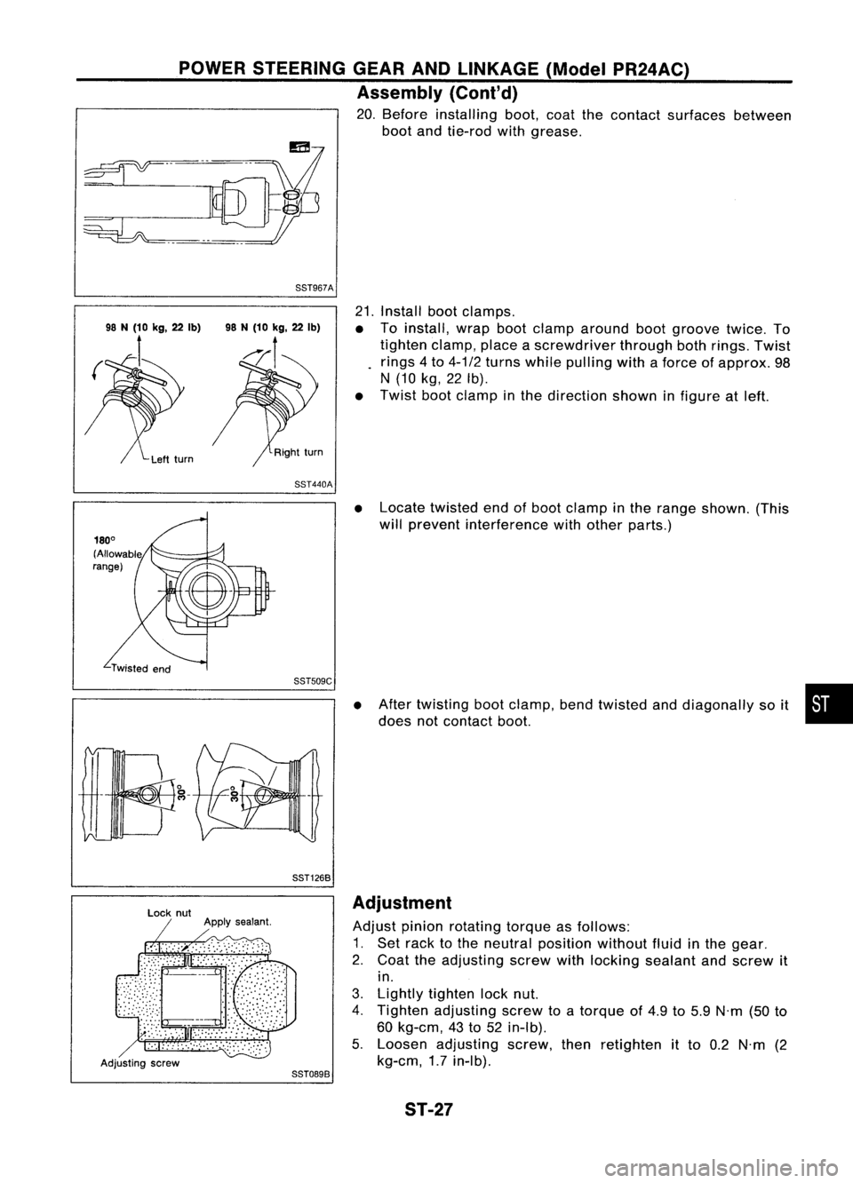
20. Before installing boot,coatthecontact surfaces between
boot andtie-rod withgrease.
88T967A
21.Install bootclamps.
• Toinstall, wrapbootclamp around bootgroove twice.To
tighten clamp,placeascrewdriver throughbothrings. Twist
rings 4to 4-1/2 turns while pulling withaforce ofapprox. 98
N (10 kg,22Ib).
• Twist bootclamp inthe direction showninfigure atleft.
88T440A
•Locate twisted endofboot clamp inthe range shown. (This
will prevent interference withother parts.)
88TS09C
88T1268
•
After twisting bootclamp, bendtwisted anddiagonally soit •
does notcontact boot.
Adjusting screw
88T0898Adjustment
Adjust pinionrotating torqueasfollows:
1. Set rack tothe neutral position withoutfluidinthe gear.
2. Coat theadjusting screwwithlocking sealant andscrew it
in.
3. Lightly tighten locknut.
4. Tighten adjusting screwtoatorque of4.9 to5.9 N'm (50to
60 kg-em, 43to52 in-Ib).
5. Loosen adjusting screw,thenretighten itto 0.2 N'm (2
kg-em, 1.7in-Ib).
ST-27
Page 1694 of 1701
POWERSTEERING GEARANDLINKAGE (ModelPR24AC)
Adjustment (Cont'd)
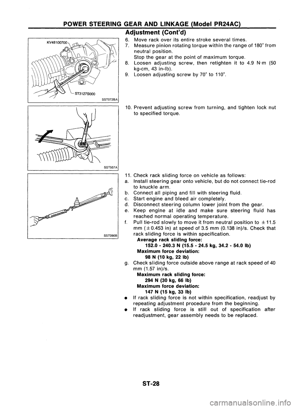
6. Move rackover itsentire stroke several times.
7. Measure pinionrotating torquewithintherange of180° from
neutral position.
Stop thegear atthe point ofmaximum torque.
8. Loosen adjusting screw,thenretighten itto 4.9 N'm (50
kg-em, 43in-Ib).
9. Loosen adjusting screwby70° to110°.
SST072BA
10.Prevent adjusting screwfromturning, andtighten locknut
to specified torque.
SST557A
SST090B
11.
Check racksliding forceonvehicle asfollows:
a. Install steering gearontovehicle, butdonot connect tie-rod
to knuckle arm.
b. Connect allpiping andfillwith steering fluid.
c. Start engine andbleed aircompletely.
d. Disconnect steeringcolumnlowerjointfrom thegear.
e. Keep engine atidle and make suresteering fluidhas
reached normaloperating temperature.
f. Pull tie-rod slowlytomove itfrom neutral position to
:l:
11.5
mm
(:l:
0.453 in)atspeed of3.5 mm (0.138 in)/s.Check that
rack sliding forceiswithin specification.
Average racksliding force:
152.0 -240.3 N(15.5 .24.5 kg,34.2.54.0 Ib)
Maximum forcedeviation:
98 N(10 kg,22Ib)
g. Check sliding forceoutside aboverangeatrack speed of40
mm (1.57 in)/s.
Maximum racksliding force:
294 N(30 kg, 66Ib)
Maximum forcedeviation:
147 N(15 kg, 33Ib)
• Ifrack sliding forceisnot within specification, readjustby
repeating adjustment procedurefromthebeginning.
• If
rack sliding forceisstill outofspecification after
readjustment, gearassembly needstobe replaced.
ST-28
Page 1695 of 1701
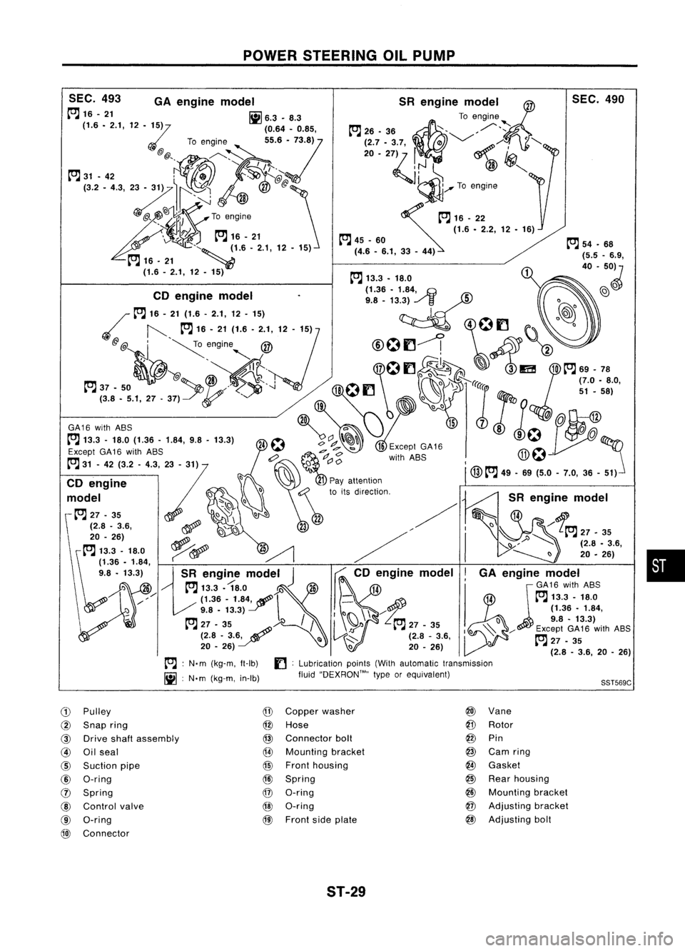
POWERSTEERING OILPUMP
•
SST569C
SEC.
490
SR engine model~
To engine
~26. 36~ ,/"~
;~7 ..
':ij m '-/
~/i<> ·"-
~':J ~
@
'CJ!I",
1~ ........To engine
~16_22 (1.6•2.2, 12•16)
~ 45-60
(4.6 -6.1, 33-44)
SEC.
493 GAengine model
~16-21 [ij6.3.8.3
(1.6. 2.1,12
'Z5)
(0.64.0.85,
To engine
55.6:/73.8)
@ @" ./'----~
, "I
/e;..
~ 31•42 ',.., 0
.'$>J
K@
J:
<~~~iX':I~
Toengine
\1f!.7~
Pm
16-21
v. ~-..
, "~ ~1.6'2.1,12•15)
~ 16. 21 _~
(1.6 -2.1, 12. 15) ~
54.68
{5.5 -6.9,
40 -50~
~ 13.3. 18.0
. (1.36•1.84,
.G
@)
0
CD engine model
9.8_13.3) ../
/3
5
0
~ 16-21 (1.6 -2.1, 12-15)
l.~
@@ ,
~engine @
@Of1--! ~
2
" ," I~
.' "@
It. 17
0
f1 ~ ~~ 3lEi! 10~
69-78
37 •50 /,
'-l
18
f1
..>
lei
51•58)
(3.8. 5.1,27.37)
0,
:r:
19
0()
W
~Q
@
GA16
with
ASS
c:>
1578
0.
Except
GA16
with
ASS
,d
e7
b
Except
GA16 ITh~ .
6? ~
<:>
withASS
-J.1;~
~ 31-42 (3.2 -4.3, 23-31) ()
C'
0
I
() @~
49.69 (5.0-7.0,36 -51)
CD engine
:7 ~~
21
Pay attention
d I
f:j
0:\
toits direction.
mo e -'" ()
-~
~ 27-35 \)~
00
22
(2.8 -3.6, ~,~
23
20 _26)
ri /
~ 13.3 -18.0 ~~
2~ /
~1'36 •1.84,
9.8 •13.3)
13R
engi~e
model
J ~
CD engine model
I
') 26 ~
13.3. 18.0
Y.l~6 14
jGA16
with
ASS
/// (1.36-
1.84f \
-\:f
14~
13.3 -18.0
9.8 •13.3)
I() \\"-/
(1.36•1.84,
/ 09.8-13.3)
~ 27.35:~)-e /
I
\~'l ~
27-35
~l)~ / Except
GA16
with
ASS
(2.8 -3.6~ III~..::::-- (2.8-3.6, ~27•35
20 •26) \)20-26) ~ (2.8_3.6, 20_26)
~ :N'm (kg-m, It-Ib)
f]:
Lubrication points(Withautomatic transmission
[ij :
N'm (kg-m, in-Ib) fluid''DEXRON™,, typeorequivalent)
CD
Pulley
@
Copper washer @
Vane
@
Snap ring
@
Hose
@
Rotor
@ Drive shaftassembly
@
Connector boll
@
Pin
@ Oilseal
@
Mounting bracket
@
Carn ring
@
Suction pipe
@
Front housing
@
Gasket
@
O-ring
@l
Spring
@
Rear housing
0
Spring
@
O-ring
@
Mounting bracket
@
Control valve @O-ring
@
Adjusting bracket
@ O-ring
@)
Front sideplate @
Adjusting boll
@)
Connector
ST-29
Page 1696 of 1701
POWERSTEERING OILPUMP
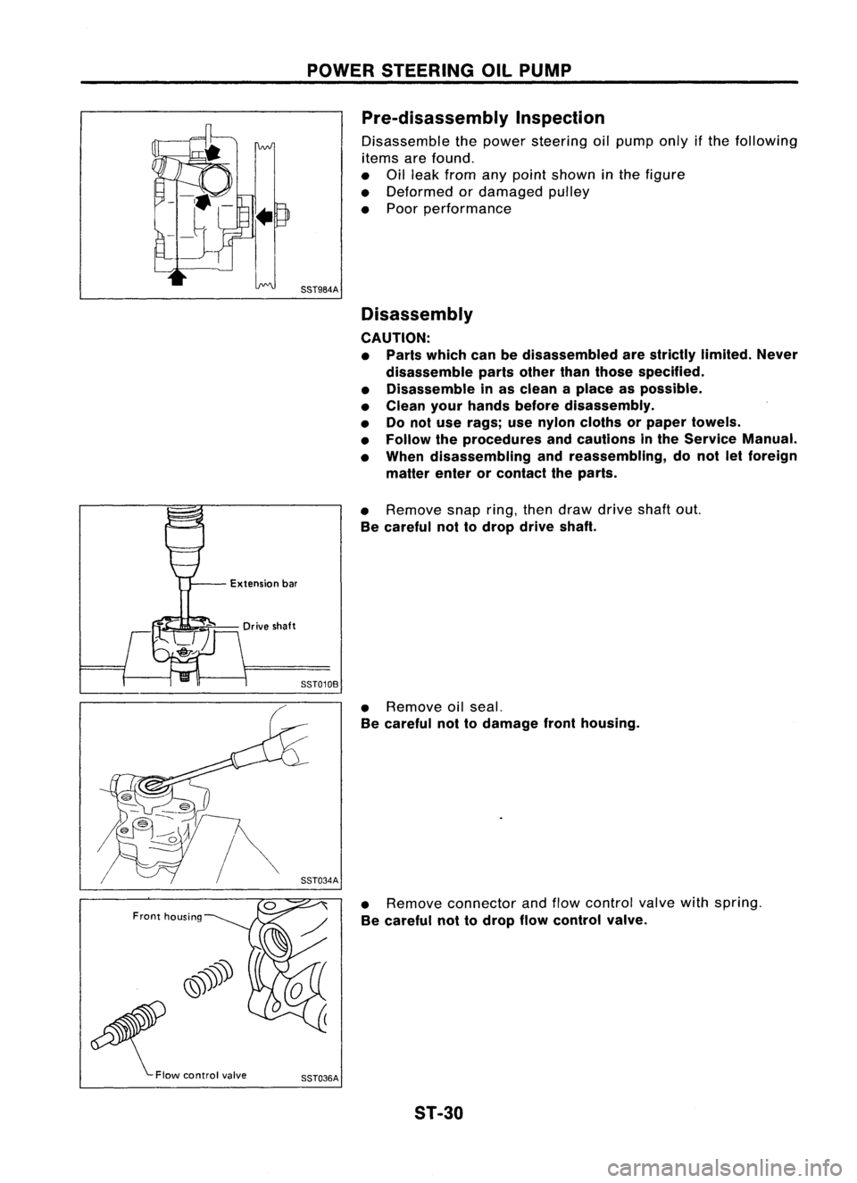
Pre-disassembly Inspection
Disassemble thepower steering oilpump onlyifthe following
items arefound.
• Oilleak from anypoint shown inthe figure
• Deformed ordamaged pulley
• Poor performance
SST984A Disassembly
CAUTION: • Parts which canbedisassembled arestrictly limited. Never
disassemble partsother thanthose specified.
• Disassemble inas clean aplace aspossible.
• Clean yourhands before disassembly.
• Donot use rags; usenylon cloths orpaper towels.
• Follow theprocedures andcautions inthe Service Manual.
• When disassembling andreassembling, donot letforeign
matter enterorcontact theparts.
Front housing Extension
bar
•
Remove snapring,thendraw drive shaftout.
Be careful nottodrop drive shaft.
SST010B
•Remove oilseal.
Be careful nottodamage fronthousing.
• Remove connector andflow control valvewithspring.
Be careful nottodrop flowcontrol valve.
SST036A 5T-30
Page 1697 of 1701
POWERSTEERING OILPUMP
Inspection
• Ifpulley iscracked ordeformed, replaceit.
• Ifan oil leak isfound around pulleyshaftoilseal, replace
the seal.
• Ifserration onpulley orpulley shaftisdeformed orworn,
replace it.
Rear housing side
Fronthousing side
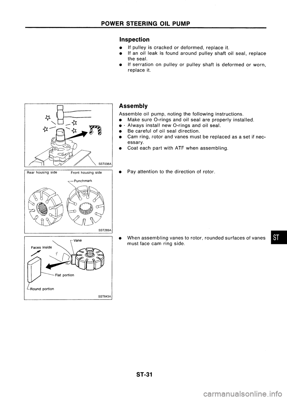
Assembly
Assemble oilpump, notingthefollowing instructions.
• Make sureO-rings andoilseal areproperly installed.
• .Always installnewO-rings andoilseal.
• Becareful ofoil seal direction.
• Cam ring,rotor andvanes mustbereplaced asaset ifnec-
essary.
• Coat each partwith ATFwhen assembling.
• Pay attention tothe direction ofrotor.
SST289A
Faces inside
./' 'I(}
~
Flatportion
SST843A
•
When assembling vanestorotor, rounded surfaces ofvanes •
must facecam ringside.
ST-31
Page 1698 of 1701
POWERSTEERING OILPUMP
Assembly (Cont'd)
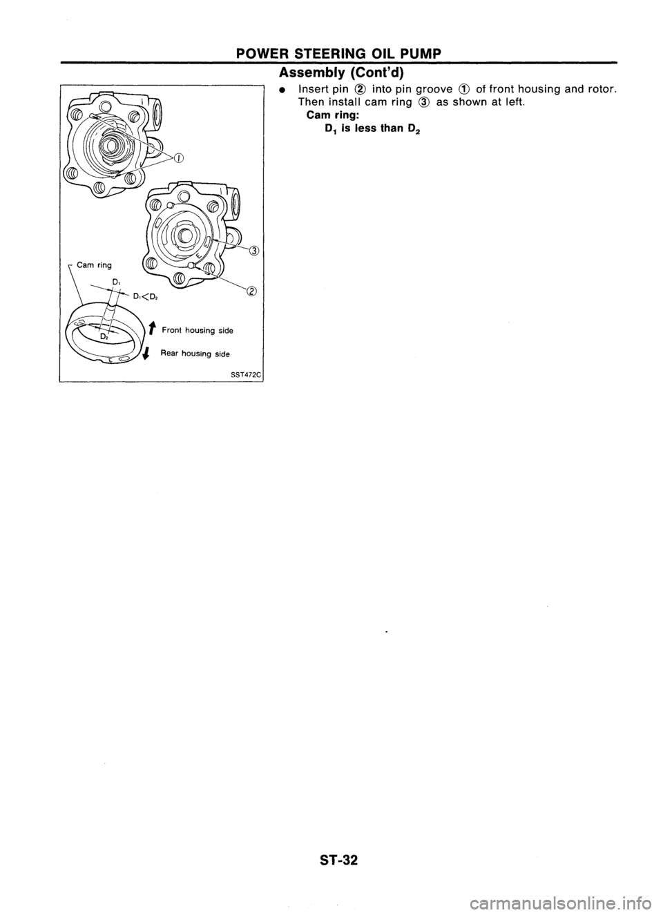
• Insert pin
CID
into pingroove
CD
offront housing androtor.
Then install earnring
CID
asshown atleft.
earn ring:
D
1
isless than D
2
SST472C
ST-32
Page 1699 of 1701
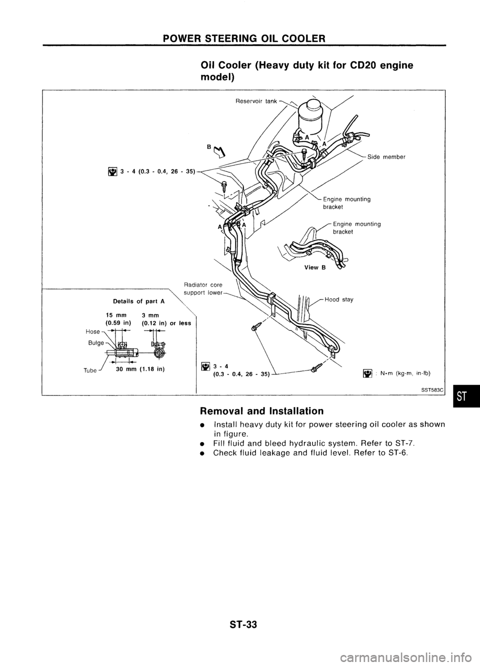
POWERSTEERING OILCOOLER
Oil Cooler (Heavy dutykitfor CD20 engine
model)
Removal andInstallation
• Install heavydutykitfor power steering oilcooler asshown
in figure.
• Fill fluid andbleed hydraulic system.RefertoST-7.
• Check fluidleakage andfluid level. Refer toST-6.
Hose
Bulge
Tube
~
3-4 (0.3 -0.4, 26-35)
Details ofpart A
15
mm
3
mm
(0.59 in) (0.12in)orless
.1 I-
30
mm
(1.18
in)
Reservoir
lank
~ 3-4
(0.3 -0.4, 26-35)
~
Enginemounting
/~bracket
\~ ~~eWB~
~•N.m (kg-m, in-Ib)
SST583C
•
ST-33
Page 1700 of 1701
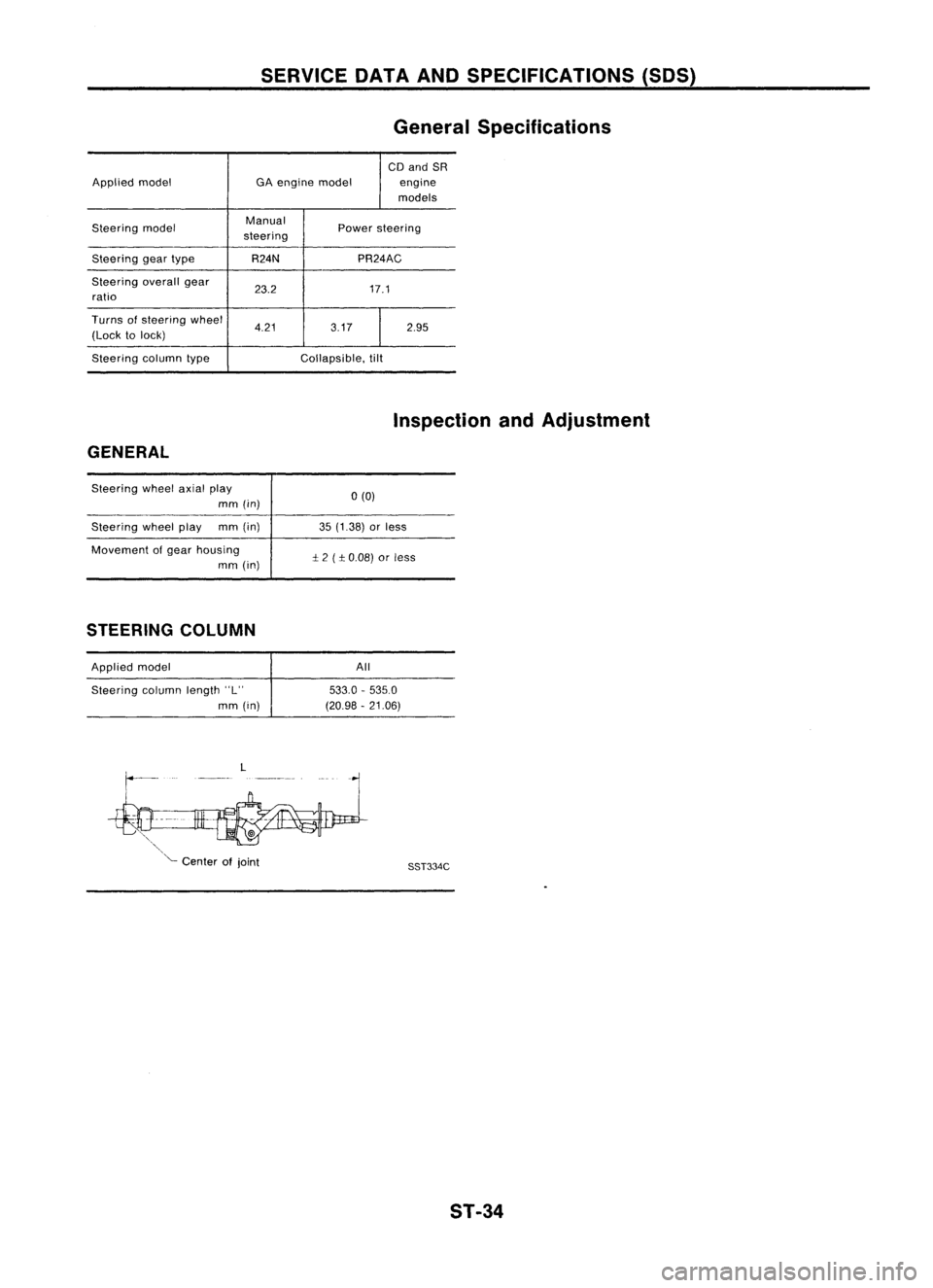
SERVICEDATAANDSPECIFICATIONS (SOS)
General Specifications
CD and SR
Applied model GAengine model engine
models
Steering model Manual
Powersteering
steering
Steering geartype R24N PR24AC
Steering overallgear
23.2 17.1
ratio
Turns ofsteering wheel
4.21 3.172.95
(Lock tolock)
Steering columntype Collapsible,tilt
Inspection andAdjustment
GENERAL
Steering wheelaxialplay
mm (in)
Steering wheelplay mm(in)
Movement ofgear housing
mm (in)
STEERING COLUMN
Applied model
Steering columnlength"L"
mm (in)
L
'"
'- Center ofjoint 0(0)
35 (1.38) orless
:!:
2 (
:!:
0.08) orless
All
533.0 -535.0
(20.98 -21.06)
SST334C
ST-34