NISSAN ALMERA N15 1995 Service Manual
Manufacturer: NISSAN, Model Year: 1995, Model line: ALMERA N15, Model: NISSAN ALMERA N15 1995Pages: 1701, PDF Size: 82.27 MB
Page 1671 of 1701
ON-VEHICLESERVICE
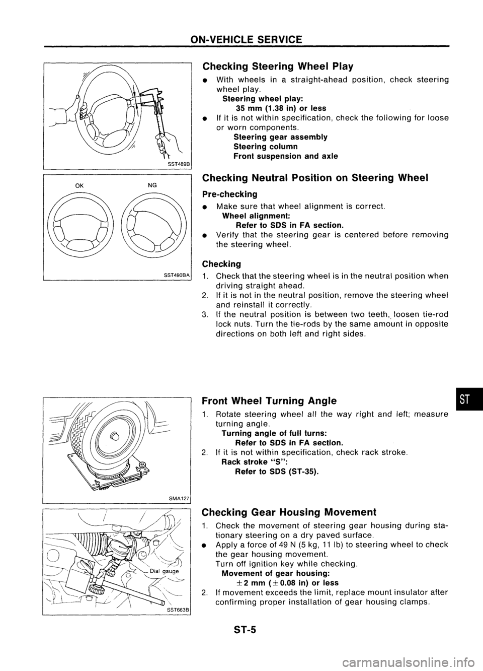
Checking SteeringWheelPlay
• With wheels inastraight-ahead position,checksteering
wheel play.
Steering wheelplay:
35 mm (1.38 in)orless
• Ifit is not within specification, checkthefollowing forloose
or worn components.
Steering gearassembly
Steering column
Front suspension andaxle
SST489B
OK
NGChecking
NeutralPosition onSteering Wheel
Pre-checking
• Make surethatwheel alignment iscorrect.
Wheel alignment:
Refer toSOS inFA section.
• Verify thatthesteering geariscentered beforeremoving
the steering wheel.
Checking
SST490BA
1.Check thatthesteering wheelisin the neutral position when
driving straight ahead.
2. Ifit is not inthe neutral position, removethesteering wheel
and reinstall itcorrectly.
3. Ifthe neutral position isbetween twoteeth,. loosen tie-rod
lock nuts. Turnthetie-rods bythe same amount inopposite
directions onboth leftand right sides.
Front Wheel Turning Angle •
1. Rotate steering wheelallthe way right andleft;measure
turning angle.
Turning angleoffull turns:
Refer toSOS inFA section.
2. Ifit is not within specification, checkrackstroke.
Rack stroke
"S":
Refer toSOS (ST-35).
SMA127 Checking GearHousing Movement
1. Check themovement ofsteering gearhousing duringsta-
tionary steering onadry paved surface.
• Apply aforce of49 N(5 kg, 11Ib) tosteering wheeltocheck
the gear housing movement.
Turn offignition keywhile checking.
Movement ofgear housing:
:I:
2 mm
(:I:
0.08 in)orless
2. Ifmovement exceedsthelimit, replace mountinsulator after
confirming properinstallation ofgear housing clamps.
ST-5
Page 1672 of 1701
ON-VEHICLESERVICE
Checking andAdjusting DriveBelts(Forpower
steering)
Refer to"Checking DriveBelts" for"ENGINE MAINTENANCE"
in MA section.
SST476C
S
r
SST681B Checking
Fluidlevel
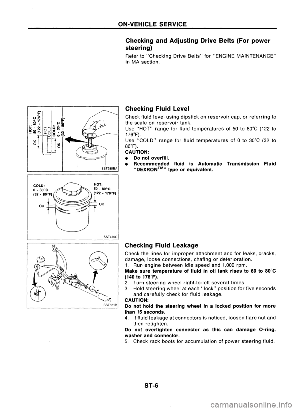
Check fluidlevel using dipstick onreservoir cap,orreferring to
the scale onreservoir tank.
Use "HOT" rangeforfluid temperatures of50 to80°C (122to
176°F).
Use "COLD" rangeforfluid temperatures of0to 30°C (32to
86°F).
CAUTION:
• Donot overfill.
• Recommended fluidisAutomatic Transmission Fluid
''DEXRON™,, typeorequivalent.
Checking Fluidleakage
Check thelines forimproper attachment andforleaks, cracks,
damage, looseconnections, chafingordeterioration.
1. Run engine between idlespeed and1,000 rpm.
Make suretemperature offluid inoil tank rises to60 to80°C
(140 to176°F).
2. Turn steering wheelright-to-Ieft severaltimes.
3. Hold steering wheelateach "lock" position forfive seconds
and carefully checkforfluid leakage.
CAUTION:
Do not hold thesteering wheelinalocked position formore
than 15seconds.
4. Iffluid leakage atconnectors isnoticed, loosenflarenutand
then retighten.
Do not overtighten connectorasthis candamage O-ring,
washer andconnector.
5. Check rackboots foraccumulation ofpower steering fluid.
ST-6
Page 1673 of 1701
SST491B
SST090B ON-VEHICLE
SERVICE
Bleeding Hydraulic System
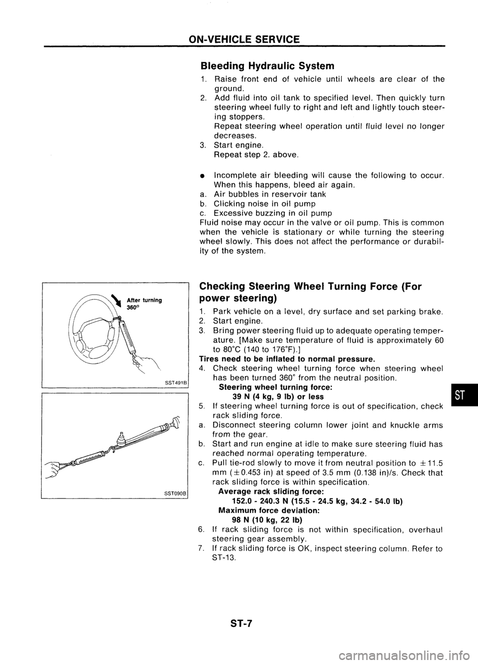
1. Raise frontendofvehicle untilwheels areclear ofthe
ground.
2. Add fluid intooiltank tospecified level.Thenquickly turn
steering wheelfullytoright andleftand lightly touchsteer-
ing stoppers.
Repeat steering wheeloperation untilfluid level nolonger
decreases.
3. Start engine.
Repeat step2.above.
• Incomplete airbleeding willcause thefollowing tooccur.
When thishappens, bleedairagain.
a. Air bubbles inreservoir tank
b. Clicking noiseinoil pump
c. Excessive buzzinginoil pump
Fluid noise mayoccur inthe valve oroil pump. Thisiscommon
when thevehicle isstationary orwhile turning thesteering
wheel slowly. Thisdoes notaffect theperformance ordurabil-
ity ofthe system.
Checking SteeringWheelTurning Force(For
power steering)
1. Park vehicle onalevel, drysurface andsetparking brake.
2. Start engine.
3. Bring power steering fluiduptoadequate operating temper-
ature. [Make suretemperature offluid isapproximately 60
to 80°C (140to176°F).]
Tires needtobe inflated tonormal pressure.
4. Check steering wheelturning forcewhen steering wheel
has been turned 360°from theneutral position.
Steering wheelturning force: •
39 N(4 kg, 9Ib) orless
5.
If
steering wheelturning forceisout ofspecification, check
rack sliding force.
a. Disconnect steeringcolumnlowerjointandknuckle arms
from thegear.
b. Start andrunengine atidle tomake suresteering fluidhas
reached normaloperating temperature.
c. Pull tie-rod slowlytomove itfrom neutral position to
::l::
11.5
mm
(::l::
0.453 in)atspeed of3.5 mm (0.138 in)/s.Check that
rack sliding forceiswithin specification.
Average racksliding force:
152.0 -240.3 N(15.5 -24.5 kg,34.2 -54.0 Ib)
Maximum forcedeviation:
98 N(10 kg, 22Ib)
6.
If
rack sliding forceisnot within specification, overhaul
steering gearassembly.
7. Ifrack sliding forceisOK, inspect steering column.Referto
ST-13.
ST-7
Page 1674 of 1701
ST27091000
.. :Direction ofoil flow Low-pressure
hose SST834-AON-VEHICLE
SERVICE
Checking Hydraulic System
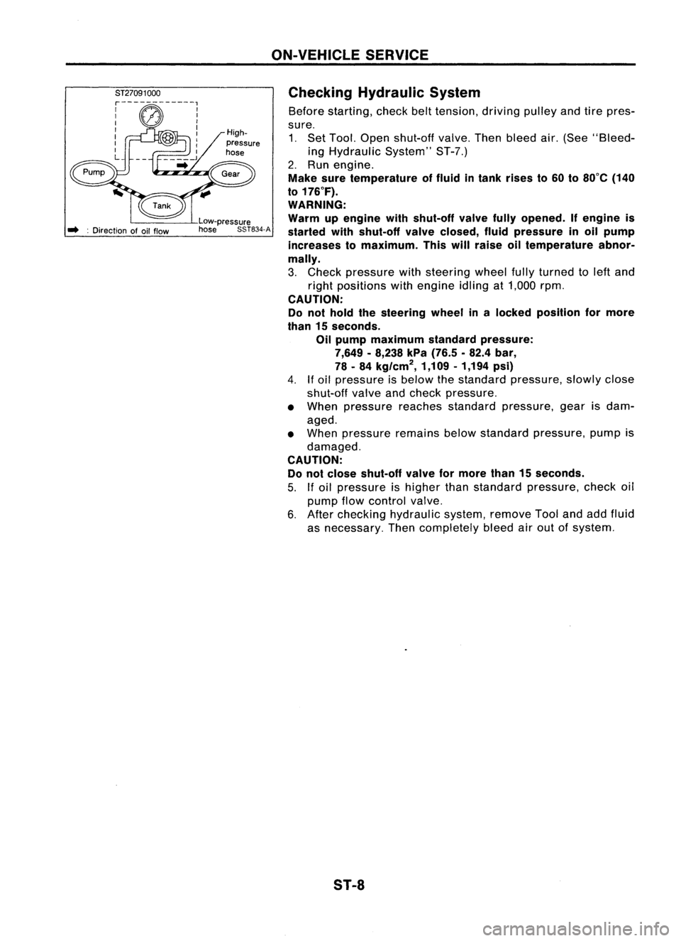
Before starting, checkbelttension, drivingpulleyandtirepres-
sure. 1. Set Tool. Open shut-off valve.Thenbleed air.(See "Bleed-
ing Hydraulic System"ST-7.)
2. Run engine.
Make suretemperature offluid intank rises to60 to80°C (140
to 176°F).
WARNING:
Warm upengine withshut-off valvefullyopened. Ifengine is
started withshut-off valveclosed, fluidpressure inoil pump
increases tomaximum. Thiswillraise oiltemperature abnor-
mally.
3. Check pressure withsteering wheelfullyturned toleft and
right positions withengine idlingat1,000 rpm.
CAUTION:
Do not hold thesteering wheelinalocked position formore
than 15seconds.
Oil pump maximum standardpressure:
7,649 -8,238 kPa(76.5 .82.4 bar,
78 -84 kg/cm
2,
1,109-1,194 psi)
4.
If
oil pressure isbelow thestandard pressure, slowlyclose
shut-off valveandcheck pressure.
• When pressure reachesstandard pressure, gearisdam-
aged.
• When pressure remainsbelowstandard pressure, pumpis
damaged.
CAUTION: Do not close shut-off valveformore than15seconds.
5.
If
oil pressure ishigher thanstandard pressure, checkoil
pump flowcontrol valve.
6. After checking hydraulic system,removeToolandaddfluid
as necessary. Thencompletely bleedairout ofsystem.
S1-8
Page 1675 of 1701
![NISSAN ALMERA N15 1995 Service Manual STEERINGWHEELANDSTEERING COLUMN
Removal andInstallation
SEC. 484.487.488
_~ ~4.0-4.9 (0.4 -0.5, 35-43)
ij] :
N.m (kg-m, in-Ib)
co;J :
N.m (kg-m. ft-Ib) With
airbag
Withoutairbag
SST538C
G)
Airb NISSAN ALMERA N15 1995 Service Manual STEERINGWHEELANDSTEERING COLUMN
Removal andInstallation
SEC. 484.487.488
_~ ~4.0-4.9 (0.4 -0.5, 35-43)
ij] :
N.m (kg-m, in-Ib)
co;J :
N.m (kg-m. ft-Ib) With
airbag
Withoutairbag
SST538C
G)
Airb](/img/5/57349/w960_57349-1674.png)
STEERINGWHEELANDSTEERING COLUMN
Removal andInstallation
SEC. 484.487.488
_~ ~4.0-4.9 (0.4 -0.5, 35-43)
ij] :
N.m (kg-m, in-Ib)
co;J :
N.m (kg-m. ft-Ib) With
airbag
Withoutairbag
SST538C
G)
Airbag module
@
Horn pad
@
Steering wheel
@
Spiral cable
@
Column cover
@
Combination switch
(J)
Steering columnassembly
@
Lower joint
@
Boot
CAUTION (SRSmodels only): •
• The rotation ofthe spiral cable(SRS"Airbag" component
part) islimited. Ifthe steering gearmust beremoved, set
the front wheels inthe straight-ahead direction.Donot
rotate thesteering columnwhilethesteering gearis
removed.
• Remove thesteering wheelbefore removing thesteering
lower jointtoavoid damaging theSRS spiral cable.
STEERING WHEEL
With AirBag
• Remove airbag module andspiral cable.
Refer to"Removal -Air Bag Module andSpiral Cable",
"SUPPLEMENTAL RESTRAINTSYSTEM"inRS section.
SBF812E ST-9
Page 1676 of 1701
STEERINGWHEELANDSTEERING COLUMN
Removal andInstallation (Cont'd)
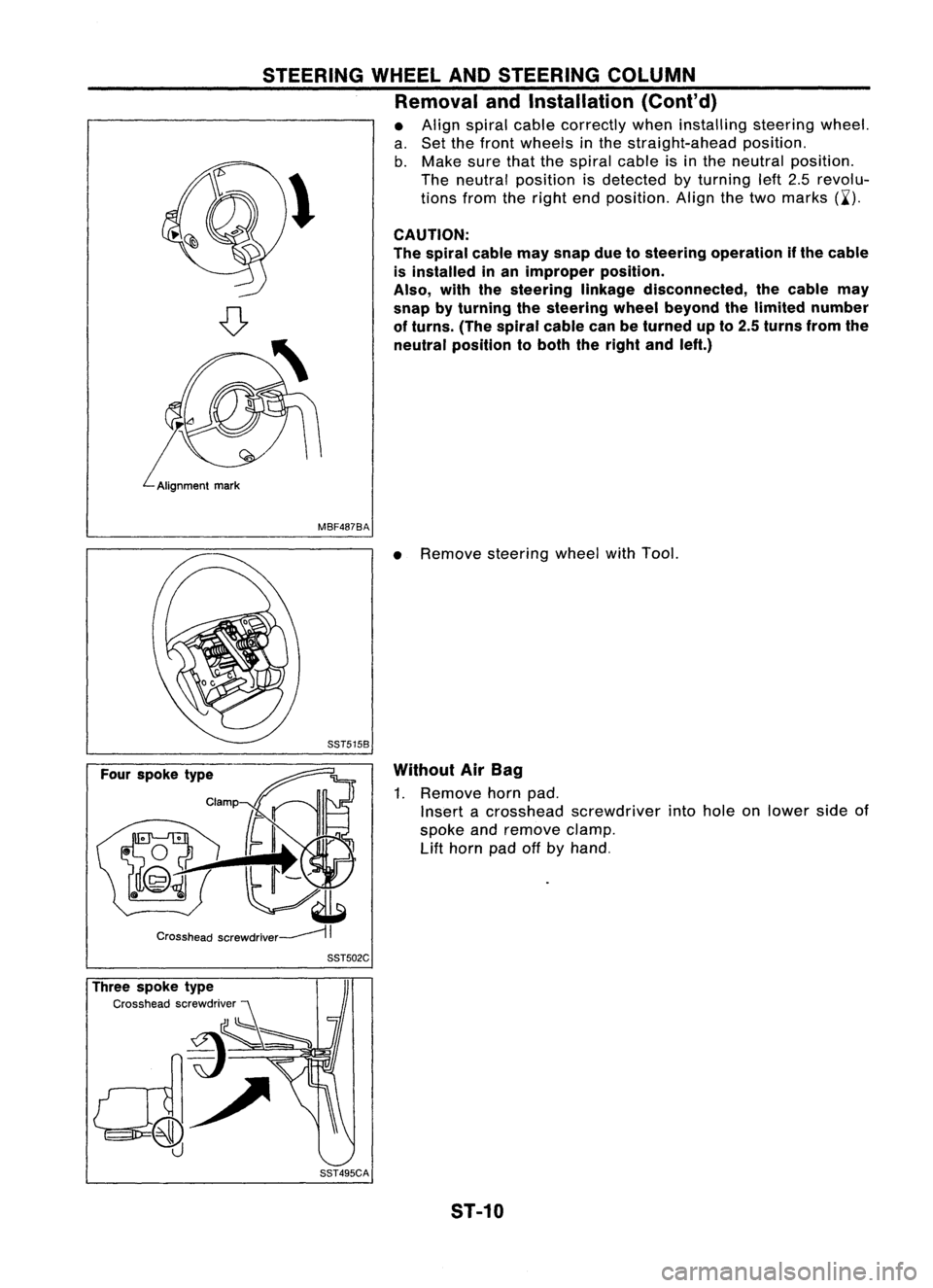
• Align spiral cablecorrectly wheninstalling steeringwheel.
a. Set thefront wheels inthe straight-ahead position.
b. Make surethatthespiral cableisin the neutral position.
\ Theneutral position isdetected byturning left2.5revolu-
~ tionsfromtheright endposition. Alignthetwo marks (~').
CAUTION:
The spiral cablemaysnap duetosteering operation ifthe cable
is installed inan improper position.
Also, withthesteering linkagedisconnected, thecable may
snap byturning thesteering wheelbeyond thelimited number
of turns. (Thespiral cablecanbeturned upto2.5 turns fromthe
neutral position toboth theright andleft.)
MBF487BA
•Remove steering wheelwithTool.
Without AirBag
1. Remove hornpad.
Insert acrosshead screwdriver intohole onlower sideof
spoke andremove clamp.
Lift
horn padoffbyhand.
Three spoke type
Cross headscrewdriver SST502C
SST495CA ST-10
Page 1677 of 1701
STEERINGWHEELANDSTEERING COLUMN
Removal andInstallation (Cont'd)
Two spoke type
Clamp
Crosshead screwdriver~
II
SST503C
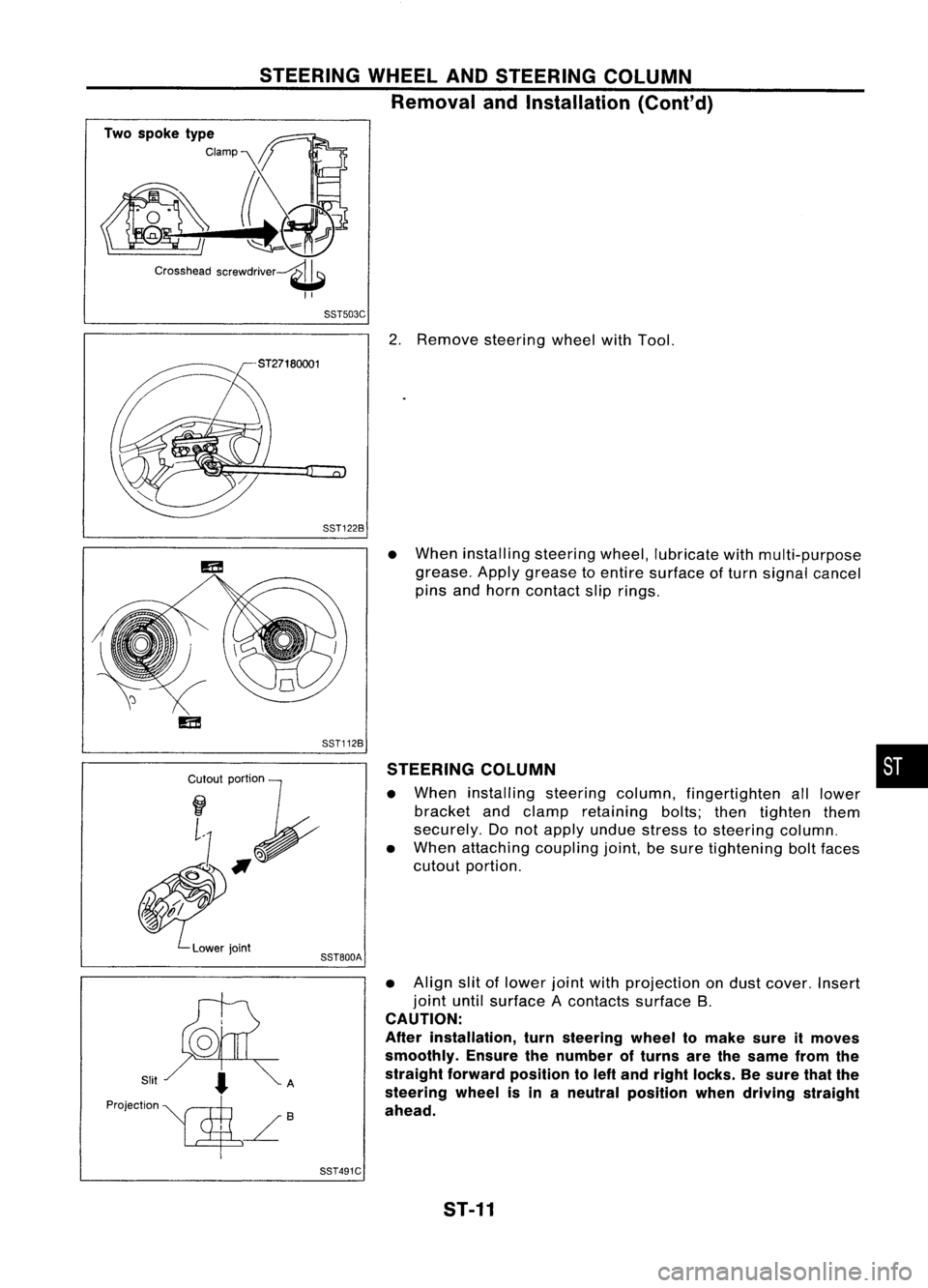
2.Remove steering wheelwithTool.
SST122B
Cr~I~I;~
~#f
~.'".
Lowerjoint
SST112B
SST800A
•
When installing steeringwheel,lubricate withmulti-purpose
grease. Applygrease toentire surface ofturn signal cancel
pins andhorn contact sliprings.
STEERING COLUMN
• When installing steeringcolumn,fingertighten alllower
bracket andclamp retaining bolts;thentighten them
securely. Donot apply undue stress tosteering column.
• When attaching couplingjoint,besure tightening boltfaces
cutout portion.
• Align slitoflower jointwithprojection ondust cover. Insert
joint untilsurface Acontacts surfaceB.
CAUTION:
After installation, turnsteering wheeltomake sureitmoves
smoothly. Ensurethenumber ofturns arethesame fromthe
straight forward position toleft and right locks. Besure thatthe
steering wheelisin aneutral position whendriving straight
ahead.
•
SST491C ST-11
Page 1678 of 1701
SEC.488 STEERING
WHEELANDSTEERING COLUMN
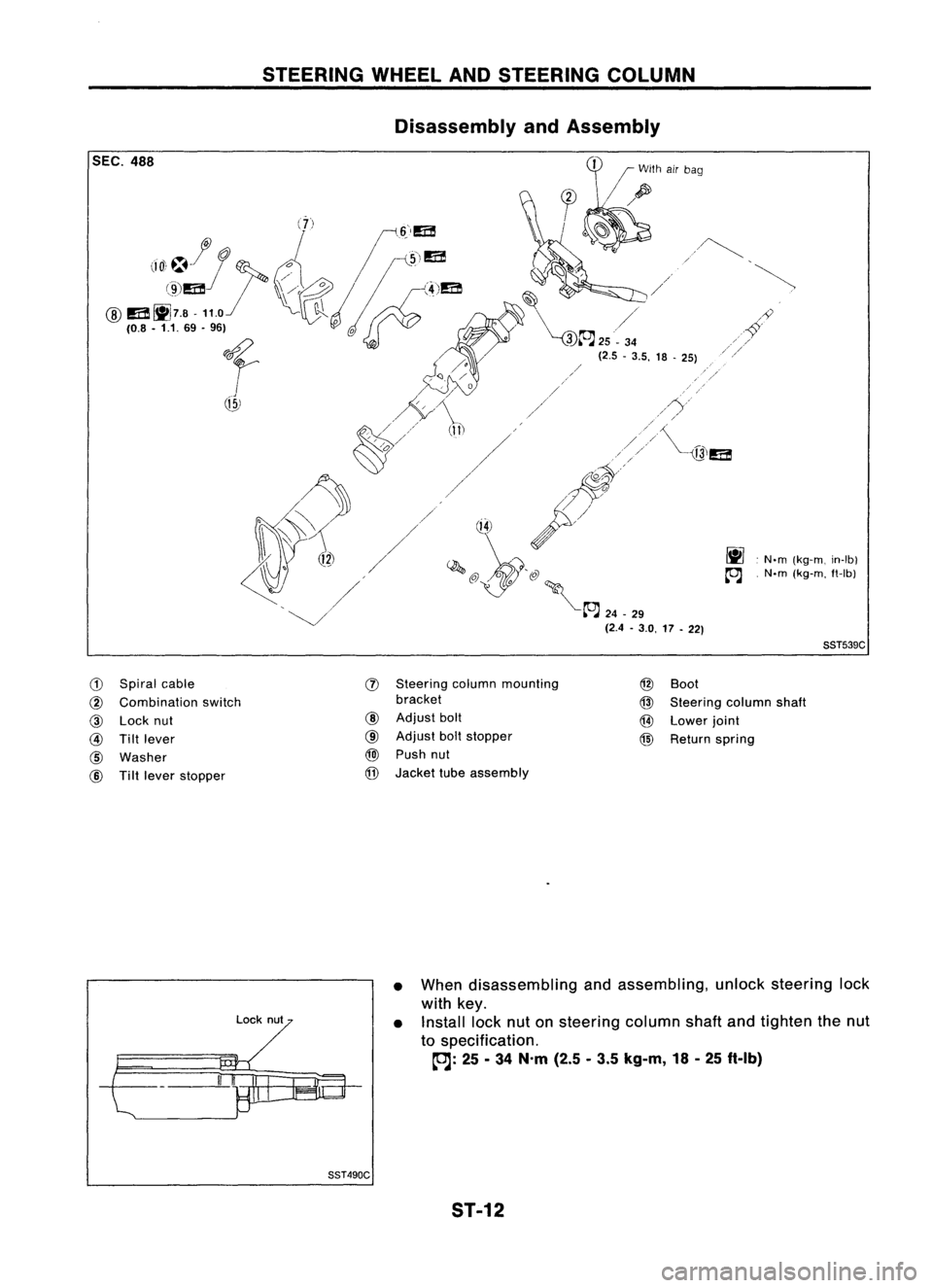
Disassembly andAssembly
~.N.m (kg-m, in-Ib)
~ .N.m (kg-m, ft-Ib)
SST539C
G)
Spiral cable
@
Combination switch
@
Lock nut
@
Tiltlever
@
Washer
@
Tiltlever stopper
!J)
Steering columnmounting
bracket
@
Adjust bolt
CID
Adjust boltstopper
@J
Push nut
@
Jacket tubeassembly
@
Boot
@
Steering columnshaft
@
Lower joint
@
Return spring
Lock nut
II
I
•
When disassembling andassembling, unlocksteering lock
with key.
• Install locknutonsteering columnshaftandtighten thenut
to specification.
~: 25-34 N.m (2.5-3.5 kg-m, 18-25 ft-Ib)
SST490C ST-12
Page 1679 of 1701

STEERINGWHEELANDSTEERING COLUMN
Disassembly andAssembly (Cont'd)
• Steering lock
a. Break self-shear typescrews withadrill orother appropri-
ate tool.
SST741A
b.Install newself-shear typescrews andthen cutoffself-
shear typescrew heads.
Self-shear screw
SST742A
L
-
--- ---_
..
_-------,
I
Center ofjoint
SST334C
1510.59) 15 (0.59)
Inspection
• When steering wheeldoesnotturn smoothly, checkthe
steering columnasfollows andreplace damaged parts.
a. Check column bearings fordamage orunevenness. Lubri-
cate with recommended multi-purposegreaseorreplace
steering columnasan assembly, ifnecessary.
b. Check jackettubefordeformation orbreakage. Replaceif
necessary.
• When thevehicle comesintoalight collision, checklength
ilL",
Column length
"L": •
533.0 -535.0 mm(20.98 -21.06 in)
If out ofthe specifications, replacesteering columnasan
assembly.
Tilt mechanism
• After installing steeringcolumn,checktiltmechanism oper-
ation.
Unit: mm(in)
8ST5828
ST-13
Page 1680 of 1701
MANUALSTEERING GEARANDLINKAGE (ModelR24N)
Removal andInstallation
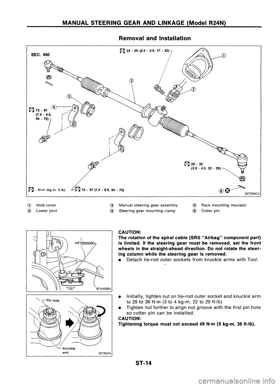
SEC. 480
A :
N.m (kg-m, tt-Ib)
(!)
Hole cover
@
Lower joint
@
Manual steering gearassembly
@
Steering gearmounting clamp
tt'J
29•39
(3.0 -4.0,22 -", ~
~
@~ SST056CA
@
Rack mounting insulator
@
Cotter pin
CAUTION:
The rotation ofthe spiral cable(SRS"Airbag" component part)
is limited.
If
the steering gearmust beremoved, setthe front
wheels inthe straight-ahead direction.Donot rotate thesteer-
ing column whilethesteering gearisremoved.
• Detach tie-rodoutersockets fromknuckle armswithTool.
• Initially, tightennutontie-rod outersocket andknuckle arm
to 29 to39 N'm (3to 4kg-m, 22to29 ft-Ib).
• Tighten nutfurther toalign nutgroove withthefirst pinhole
so cotter pincan beinstalled.
CAUTION:
Tightening torquemustnotexceed 49N.m (5kg-m, 36ft-Ib).
ST-14