roof NISSAN ALMERA N15 1995 User Guide
[x] Cancel search | Manufacturer: NISSAN, Model Year: 1995, Model line: ALMERA N15, Model: NISSAN ALMERA N15 1995Pages: 1701, PDF Size: 82.27 MB
Page 207 of 1701
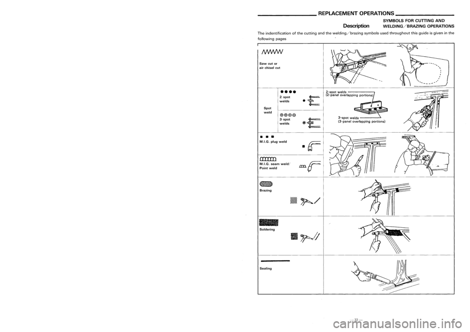
Description
_________
BODYALIGNMENT _
Body Center Marks ________
REPLACEMENTOPERATIONS _
SYMBOLS FORCUITING AND
WELDING/BRAZING OPERATIONS
..J
3-spot welds
(3-panel overlapping portions)
2-SDOt
welds
(2-panel overlapping portions)
••••
2-spot
welds
0000
3-spot
welds
Spot
weld
Brazing
Soldering
(ItIlI)
M.LG. seamweld/
Point weld
Saw
cutor
air chisel cut
•
•
•
M.LG. plugweld
-
The
indentification ofthe cutting andthewelding/brazing symbolsusedthroughout thisguide isgiven inthe
following pages
Portion F
Portion
C
Unit:
mm
Porton
H
3-Door Hatchback
and 5-Door Hatchback
• Front roof
• Second crossmember
Portion
D-Sedan
Portion E
-Sedan
Portion F
Portion E
Portion
8
Portion
G
~
Slot(7X 11)
/~/
• Rear waist panelslot
•
Cowl top
Portion
BPortion
C
Hole(4
dial
Portion
A
Portion D
Portion
A
• Rear roof
•
Upper radiator coresupport
A
mark hasbeen placed oneach partofthe body toindicate thevehicle center.Whenrepairing partsdamaged
by an accident whichmightaffectthevehicle frame(members, pillars,etc.)more accurate, effectiverepairwill
be possible byusing these marks together withbody alignment data.
Portion G
3-door and5-door Hatchback
Lozenge
mark
Portion
H
3-door and5-door Hatchback Sealing
• Rear roof •
Rear panel
-13- -32-
Page 211 of 1701

Undercoating REPLACEMENT
OPERATIONS
Front Pillar
(Work afterhoodledge reinforcement hasbeen removed.)
116
1lIl..
(Dri pchannel)
an
(Outer)
112
c;;;;?
FR
112
112
116
Unit:mm
<:=i
FR
1lIl..
( Inner)
112
~
113 :::::-----
Service
Joint
~I!!!!!!!!iiii!!!!!i!II :
Indicates undercoated portions
The
undersides ofthe floor andwheelhouse areundercoated toprevent rust,vibration, noiseandstone
chipping.
Therefore, whensuchapanel isreplaced orrepaired, applyundercoating tothat part. Useanundercoating with
the following properties: rustpreventive, soundproof, vibration-proof, shock-resistant, adhesive,anddurable.
Precautions inundercoating
1. Donot apply undercoating toany place unless specified (suchasthe areas above themuffler andcatalytic
converter whicharesubjected toheat).
2. Donot undercoat theexhaust pipe,other partswhich become hot,androtary parts.
3. Apply bitumen waxafter applying undercoating.
2-spotwelds 3-spotwelds
M.I.G plug wel(d For3panels plugweld method )..~:
G(F:~dm
weld/
• rr= •
A
==-=.
B~
.LLLL
GTJ --- ~
-9-
-36-
Page 221 of 1701
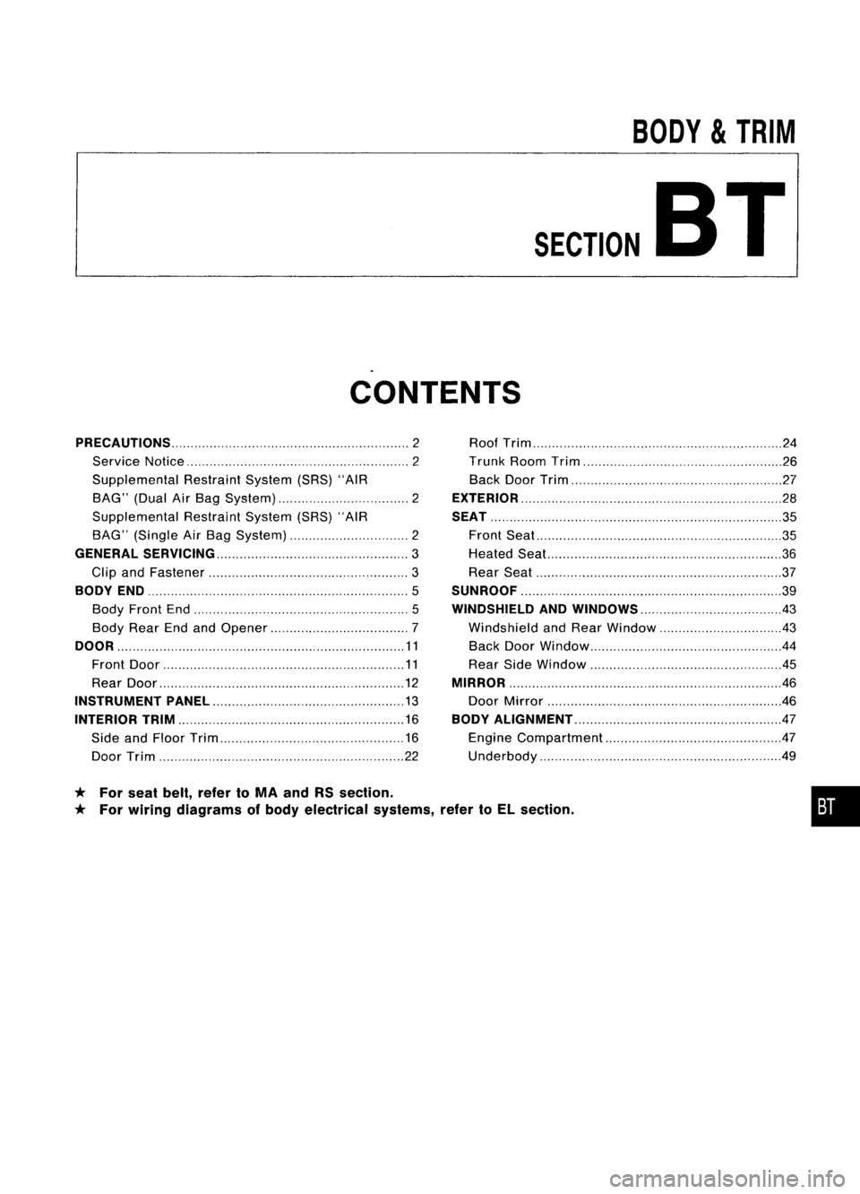
BODY
&
TRIM
SECTION
BT
CONTENTS
* For seat belt,refer toMA and RSsection.
* For wiring diagrams ofbody electrical systems,refertoEL section.
PRECAUTIONS
2
Service Notice 2
Supplemental RestraintSystem(SRS)"AIR
BAG" (DualAirBag System) 2
Supplemental RestraintSystem(SRS)"AIR
BAG" (Single AirBag System) 2
GENERAL SERViCiNG 3
Clip andFastener
3
BODY END
5
Body Front End
5
Body RearEndandOpener 7
DOOR 11
Front Door 11
Rear Door
12
INSTRUMENT PANEL
13
INTERIOR TRIM 16
Side andFloor Trim
16
Door Trim 22Roof
Trim 24
Trunk RoomTrim 26
Back DoorTrim 27
EXTERIOR 28
SEAT 35
Front Seat
35
Heated Seal... 36
Rear Seat 37
SUNROOF 39
WINDSHIELD ANDWINDOWS 43
Windshield andRear Window 43
Back DoorWindow 44
Rear SideWindow
.45
MIRROR 46
Door Mirror .46
BODY ALIGNMENT 47
Engine Compartment 47
Underbody .49
•
Page 244 of 1701
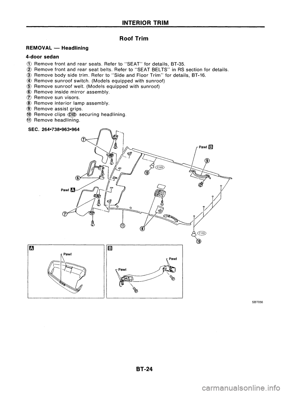
INTERIORTRIM
Roof Trim
REMOVAL -Headlining
4-door sedan
CD
Remove frontandrear seats. Referto"SEAT" fordetails, BT-35.
@
Remove frontandrear seat belts. Referto"SEAT BELTS" inRS section fordetails.
@)
Remove bodysidetrim. Refer to"Side andFloor Trim" fordetails, BT-16.
@
Remove sunroofswitch.(Models equipped withsunroof)
@
Remove sunroofwelt.(Models equipped withsunroof)
@
Remove insidemirror assembly.
([) Remove sunvisors.
@
Remove interiorlampassembly.
@
Remove assistgrips.
@)
Remove clips
@
securing headlining.
@
Remove headlining.
SEC. 264-738-963-964
9
Pawl'
Pawl SBT056
BT-24
Page 245 of 1701
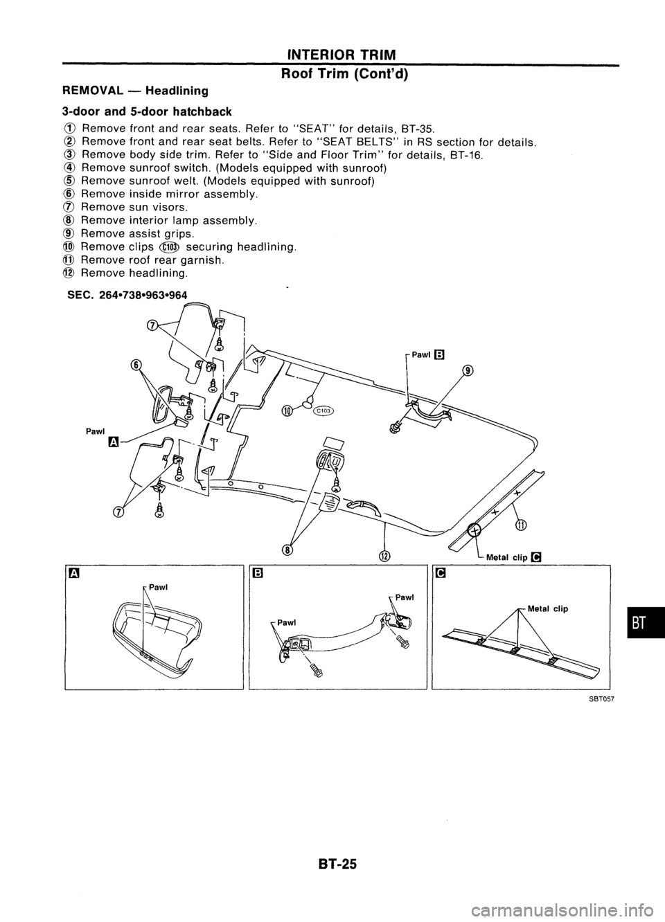
INTERIORTRIM
Roof Trim (Cont'd)
REMOVAL -Headlining
3-door and5-door hatchback
CD
Remove frontandrear seats. Referto"SEAT" fordetails, BT-35.
@
Remove frontandrear seat belts. Referto"SEAT BELTS" inRS section fordetails.
@)
Remove bodysidetrim. Refer to"Side andFloor Trim" fordetails, BT-16.
@
Remove sunroofswitch.(Models equipped withsunroof)
cID
Remove sunroofwelt.(Models equipped withsunroof)
@
Remove insidemirror assembly.
(f)
Remove sunvisors.
@
Remove interiorlampassembly.
@
Remove assistgrips.
@)
Remove clips
@
securing headlining.
(j]
Remove roofrear garnish.
@
Remove headlining.
SEC.
264-738-963-964
Pawl
•
Metal
clip
l!1
Pawlm
m
SBT05?
8T-25
Page 250 of 1701
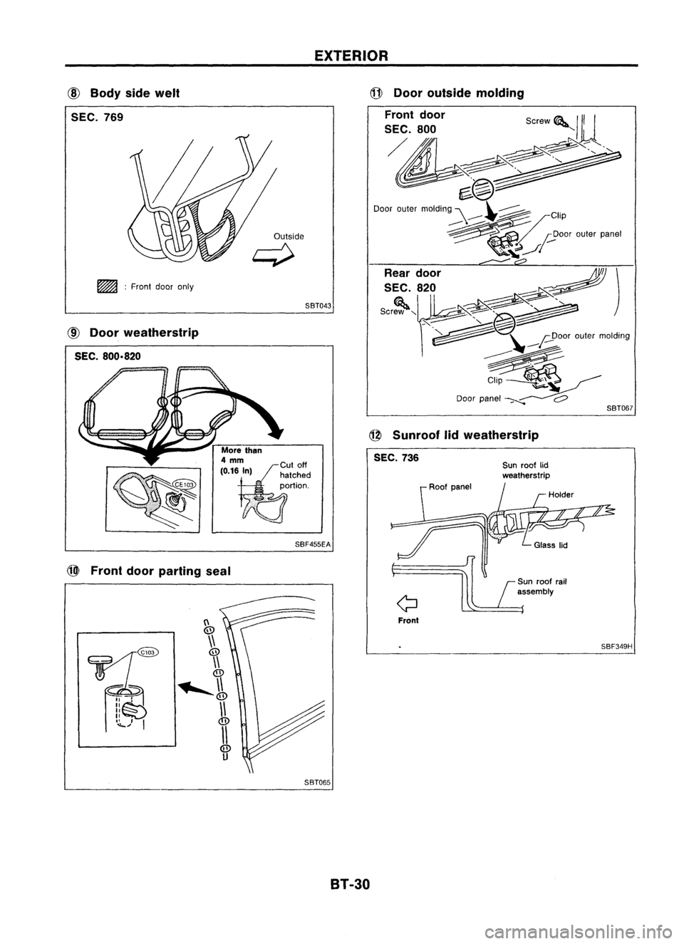
EXTERIOR
r
Sunroof rail
assembly
l
SBF349H
Front
Sun
roof lid
weatherstrip
Roof panel
SBT067
@
Door outside molding
Front door
SEC. 800 Screw'
III
~" g.@~
Door outer molding ~__
~/CIiP
~"..-/f'yoor outerpanel
Rear door ~
c:?
SEC. 820
~J
s,,~,~)
\.~ ~' "',,mold'"
CIIP~~
Door panel --~
~ 0
@
Sunroof lidweath .
S
erstnp
EC.736
SBT043
SBF455EA
d;!)de
(\
@
\\
@
\\
@
.........
\
\
@
\\
@
II
@
u
~~
::€t)£j
I.
II
.~) I
:
Front dooronly
CID
Door weatherstrip
SEC. 800.820
@
Body sidewelt
SEC. 769
@
Front doo .
r parting seal
SBT065
8T-30
Page 259 of 1701
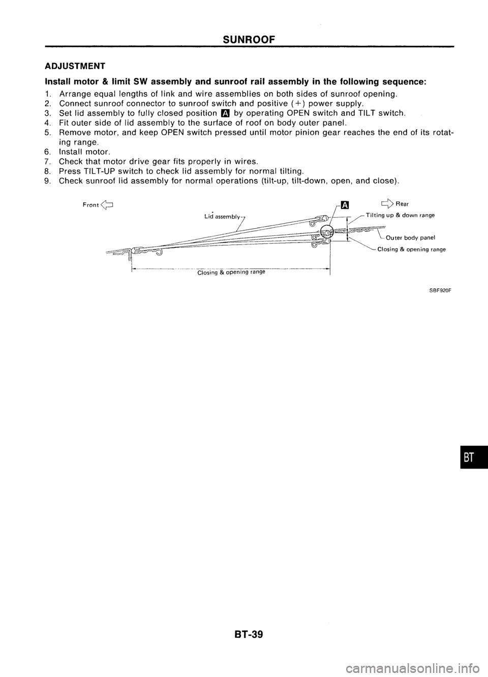
SUNROOF
ADJUSTMENT Install motor
&
limit SWassembly andsunroof railassembly inthe following sequence:
1. Arrange equallengths oflink and wire assemblies onboth sides ofsunroof opening.
2. Connect sunroofconnector tosunroof switchandpositive
(+)
power supply.
3. Set lidassembly tofully closed position
m
byoperating OPENswitch andTILT switch.
4. Fitouter sideoflid assembly tothe surface ofroof onbody outer panel.
5. Remove motor,andkeep OPEN switch pressed untilmotor pinion gearreaches theend ofits rotat-
ing range.
6. Install motor.
7. Check thatmotor drivegearfitsproperly inwires.
8. Press TILT-UP switchtocheck lidassembly fornormal tilting.
9. Check sunroof lidassembly fornormal operations (tilt-up,tilt-down, open,andclose).
FrontQ
Closing
&
opening range
81-39
ri1
9
Rear
/ Tilting up&down range
- ;:: u~
Outer bodypanel
~ Closing
&
opening range
SBF920F
•
Page 260 of 1701

SUNROOF
REMOVAL
• After anyadjustment, checksunroof operation andlidalignment.
• Handle finisher plateandglass lidwith care sonot tocause damage.
• Itis desirable foreasy installation tomark eachpoint before removal.
CAUTION:
Always workwithahelper.
Link andwire
assembly Sunroof
frame
assembly Shade
assembly
~
~
8T-40
Lid
assembly Motorassembly
Page 261 of 1701

SUNROOF
* For Wiring Diagram, referto"ELECTRIC SUNROOF" inEL section.
SEC. 736
@Motor assembly @Rear
drainassembly
7 Sunroof switchbracket
81-41
SBT081
•
Page 262 of 1701
![NISSAN ALMERA N15 1995 User Guide Linkassembly
MBF493B SUNROOF
m
Using flat-bladed screwdriver, pryshade assembly holder
off rail. Then pullshade assembly forwardtoremove itfrom
rail.
I]IIDisengage pawlsfromrail,then remove window d](/img/5/57349/w960_57349-261.png "NISSAN ALMERA N15 1995 User Guide Linkassembly
MBF493B SUNROOF
m
Using flat-bladed screwdriver, pryshade assembly holder
off rail. Then pullshade assembly forwardtoremove itfrom
rail.
I]IIDisengage pawlsfromrail,then remove window d")
Linkassembly
MBF493B SUNROOF
m
Using flat-bladed screwdriver, pryshade assembly holder
off rail. Then pullshade assembly forwardtoremove itfrom
rail.
I]IIDisengage pawlsfromrail,then remove window deflector
holder.
mUsing flat-bladed screwdriver, prystopper springoffrail
groove. Thensliderearguide backward toremove itfrom
rail.
mRemove wireandlinkassembly fromrailwhile pushing
link back withflat-bladed screwdriver.,
81-42