roof NISSAN ALMERA N15 1995 Owner's Manual
[x] Cancel search | Manufacturer: NISSAN, Model Year: 1995, Model line: ALMERA N15, Model: NISSAN ALMERA N15 1995Pages: 1701, PDF Size: 82.27 MB
Page 374 of 1701
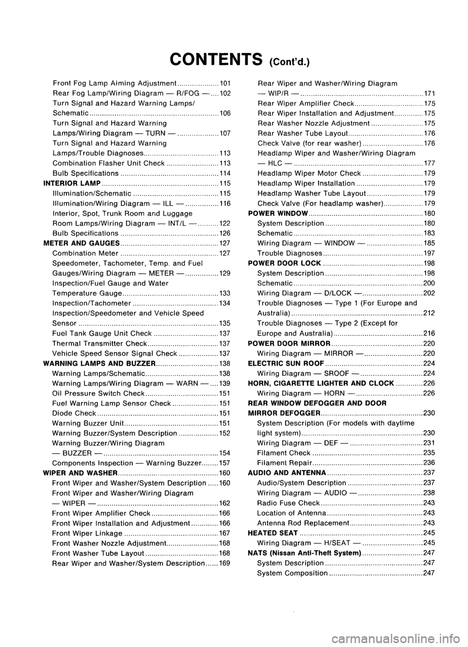
CONTENTS(Conl'd.)
Front FogLamp Aiming Adjustment.. 101
Rear FogLamp/Wiring Diagram-R/FOG -102
Turn Signal andHazard Warning Lamps/
Schematic 106
Turn Signal andHazard Warning
Lamps/Wiring Diagram-TURN - 107
Turn Signal andHazard Warning
Lamps/Trouble Diagnoses 113
Combination FlasherUnitCheck 113
Bulb Specifications 114
INTERIOR LAMP 115
Illumination/Schematic 115
Illumination/Wiring Diagram-ILL - 116
Interior, Spot,Trunk Room andLuggage
Room Lamps/Wiring Diagram-INT/L - 122
Bulb Specifications 126
METER ANDGAUGES 127
Combination Meter 127
Speedometer, Tachometer,Temp.andFuel
Gauges/Wiring Diagram-METER - 129
Inspection/Fuel GaugeandWater
Temperature Gauge 133
Inspection/Tachometer 134
Inspection/Speedometer andVehicle Speed
Sensor 135
Fuel Tank Gauge UnitCheck 137
Thermal Transmitter Check 137
Vehicle SpeedSensor SignalCheck 137
WARNING LAMPSANDBUZZER 138
Warning Lamps/Schematic 138
Warning Lamps/Wiring Diagram-WARN -139
Oil Pressure SwitchCheck 151
Fuel Warning LampSensor Check 151
Diode Check 151
Warning BuzzerUnit... 151
Warning Buzzer/System Description 152
Warning Buzzer/Wiring Diagram
- BUZZER - 154
Components Inspection-Warning Buzzer 157
WIPER ANDWASHER 160
Front Wiper andWasher/System Description160
Front Wiper andWasher/Wiring Diagram
- WIPER - 162
Front Wiper Amplifier Check 166
Front Wiper Installation andAdjustment.. 166
Front Wiper Linkage 167
Front Washer NozzleAdjustment... 168
Front Washer TubeLayout 168
Rear Wiper andWasher/System Description169Rear
Wiper andWasher/Wiring Diagram
- WIP/R - 171
Rear Wiper Amplifier Check 175
Rear Wiper Installation andAdjustment.. 175
Rear Washer NozzleAdjustment 175
Rear Washer TubeLayout.. 176
Check Valve(forrear washer) 176
Headlamp WiperandWasher/Wiring Diagram
- HLC - 177
Headlamp WiperMotorCheck 179
Headlamp WiperInstallation 179
Headlamp WasherTubeLayout.. 179
Check Valve(Forheadlamp washer) 179
POWER WINDOW 180
System Description 180
Schematic 183
Wiring Diagram -WINDOW - 185
Trouble Diagnoses 197
POWER DOORLOCK 198
System Description 198
Schematic 200
Wiring Diagram -D/LOCK - 202
Trouble Diagnoses -Type 1(For Europe and
Austral ia) 212
Trouble Diagnoses -Type 2(Except for
Europe andAustralia) 216
POWER DOORMIRROR 220
Wiring Diagram -MIRROR - 220
ELECTRIC SUNROOF 224
Wiring Diagram -SROOF - 224
HORN, CIGARETTE LIGHTERANDCLOCK 226
Wiring Diagram -HORN - 226
REAR WINDOW DEFOGGER ANDDOOR
MIRROR DEFOGGER 230
System Description (Formodels withdaytime
light system) 230
Wirin.g Diagram -DEF - 231
Filament Check 235
Fi lament Repai
r
236
AUDIO ANDANTENNA 237
Audio/System Description 237
Wiring Diagram -AUDIO - 238
Radio FuseCheck 243
Location ofAntenna 243
Antenna RodReplacement.. 243
HEATED SEAT 245
Wiring Diagram -H/SEAT - 245
NATS (Nissan Anti-Theft System) 247
System Description 247
System Composition 247
Page 377 of 1701
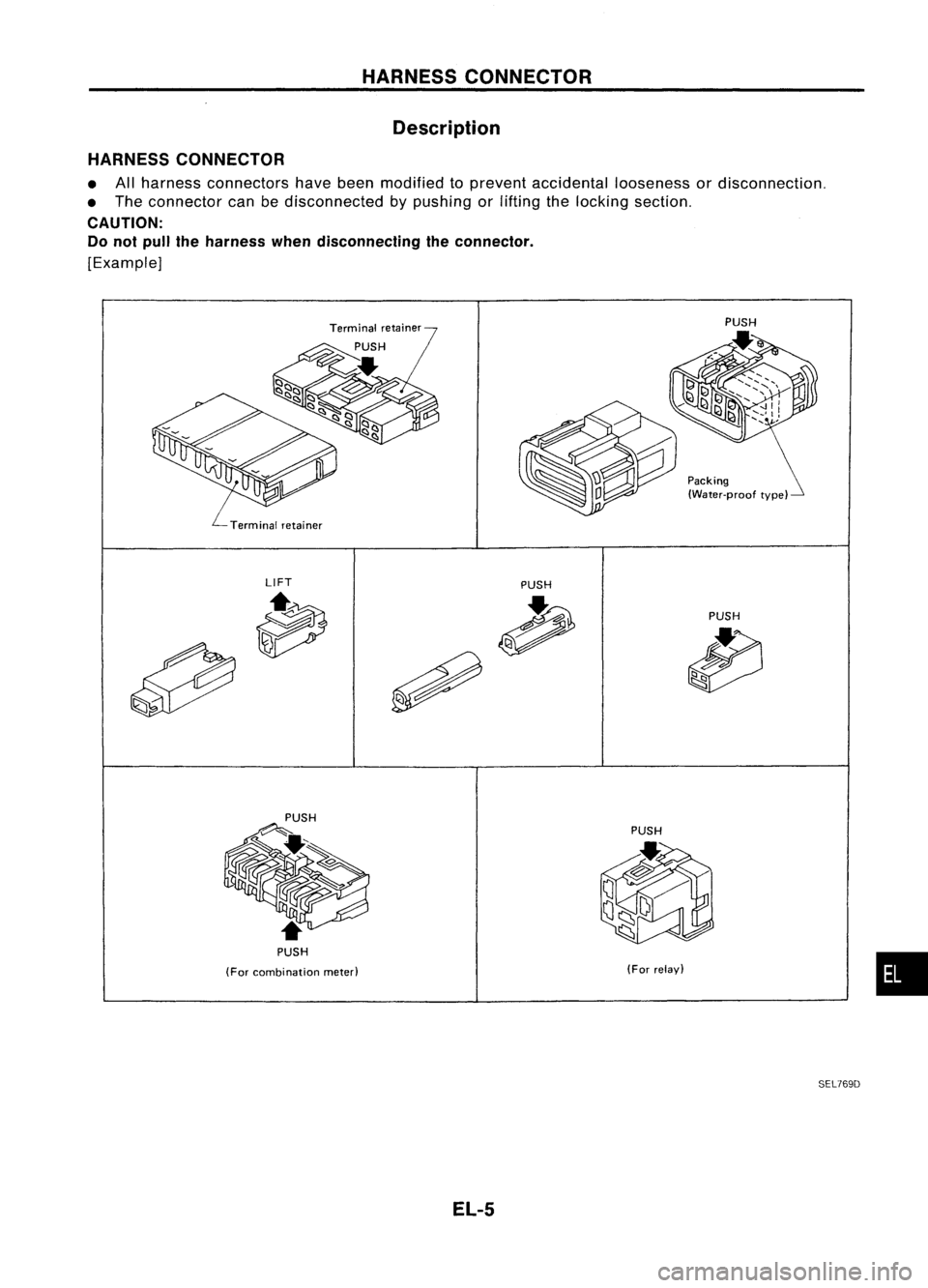
Packing(Water-proof type)
HARNESS
CONNECTOR
Description
HARNESS CONNECTOR
• Allharness connectors havebeen modified toprevent accidental loosenessordisconnection.
• The connector canbedisconnected bypushing orlifting thelocking section.
CAUTION: Do not pull theharness whendisconnecting theconnector.
[Example]
LIFT PUSH
PUSH
PUSH
(For combination meted
EL-5
PUSH
(For relay)
SEL769D
•
Page 380 of 1701
>-
a:
w
I--
I--
«
CD
75A
[ill
25A
m
30A
0
30A
lliJ
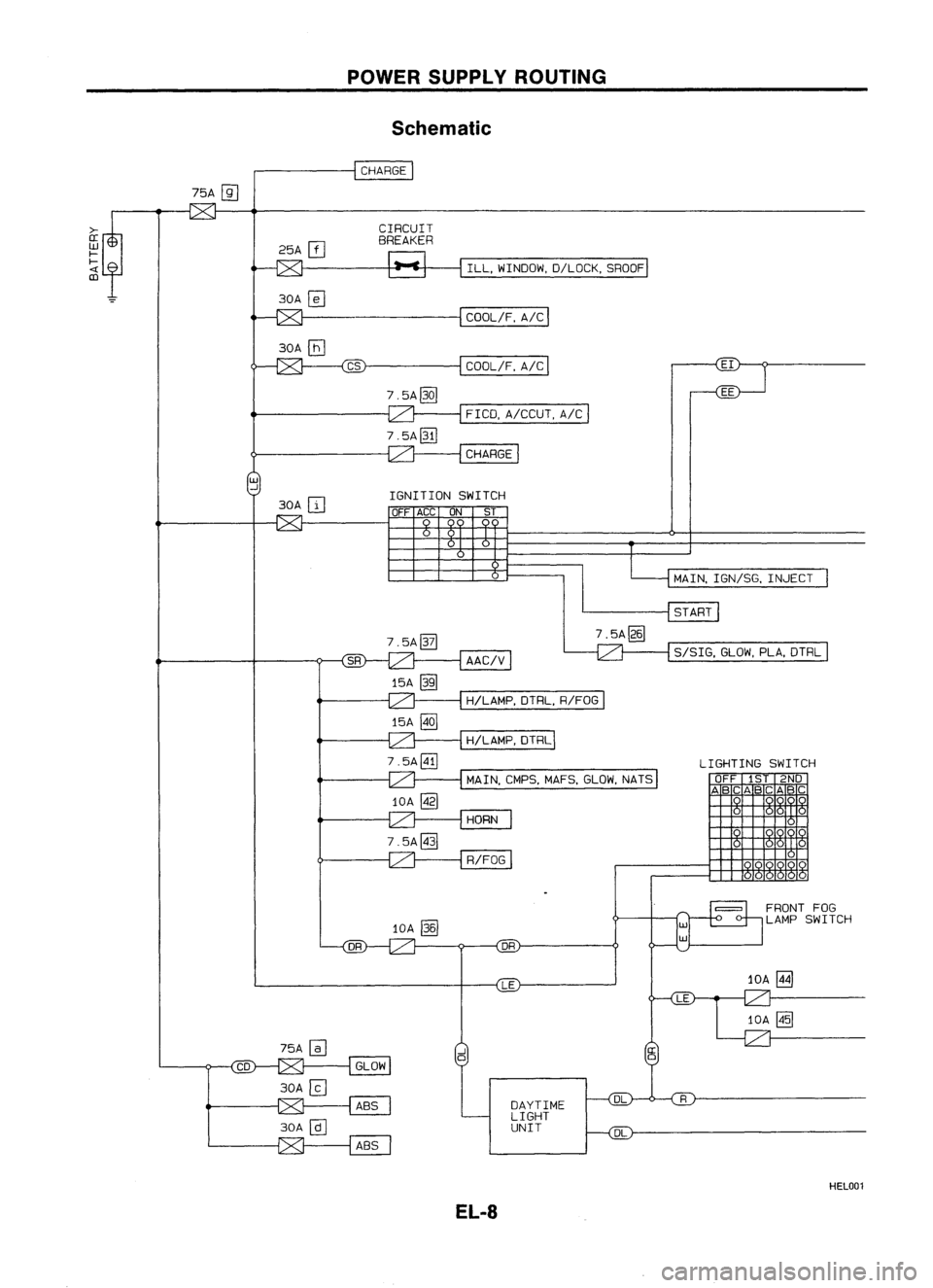
POWER
SUPPLY ROUTING
Schematic
CHARGE
CIRCUIT
BREAKER
ILL,WINDOW, D/LOCK,SROOF
I
COOl/F, A/C
I
COOl/F, A/C
7.5A@Q]
FICO,A/CCUT, A/C
7.5A@I]
CHARGE
UJ
..J
30A
ITJ
IGNITION
SWITCH
OFF ACC ON ST
7.5A~
AAC/V
15A
@ill
7.5A~
MAIN,
IGN/SG, INJECT
START
S/SIG, GLOW,PlA,DTRl
H/lAMP, DTRl,R/FOG
15A
@Q]
H/LAMP,DTRl
7.5A0J
MAIN,CMPS,MAFS,GLOW,NATS
10A ~
HORN
7.5A@]
R/FOG
10A
00
DR
LE
LIGHTING
SWITCH
OFF 1ST2ND
ABC ABCABC
FRONT FOG
lAMP SWITCH
10A
mI
CD
EL-8
DAYTIME
LIGHT
UNIT
DL
HEL001
Page 381 of 1701
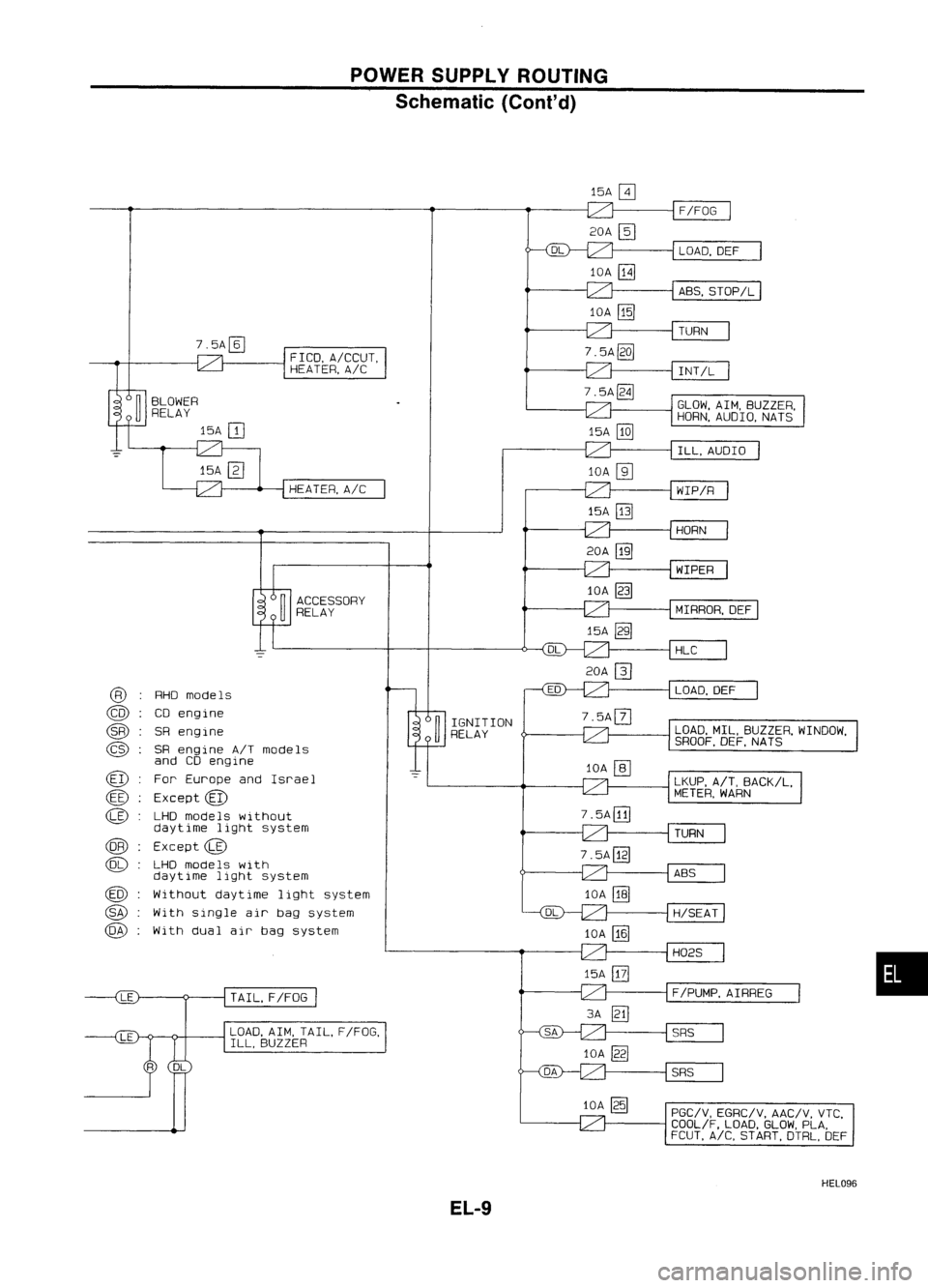
POWERSUPPLY ROUTING
Schematic (Cont'd)
l5A~
F/FOG
20A
@J
LOAD,DEF
lOA
[8J
ABS,SToP/L
lOA
[ill
TURN
FICO, A!CCUT,
HEATER, A!e
HEATER, A!e
7.5A@Q]
lOA
@]
l5A
[ill
INT/L
GLOW, AIM,BUZZER,
HORN, AUDIO, NATS
ILL, AUDIO
WIP/R
ACCESSORY
RELAY
20A
[ill
lOA ~
l5A ~ HORN
WIPER
MIRROR, DEF
HLC
20A []]
•
LOAD,
DEF
LOAD, MIL,BUZZER, WINDOW,
SROOF, DEF,NATS
LKUP, AIT,BACK/L,
METER, WARN
TURN
ABS
H/SEAT
H02S
F/PUMP, AIRREG
SRS
SRS
PGC/V, EGRC/V, AAC/V,VTC,
COOL/F, LOAD,GLOW,PLA,
FCUT, A/C,START, DTRL,DEF
3A
IE]
lOA
[ill
lOA
[ill
lOA ~
l5A
@]
7.
5A
[ill
n
IGNITION
U
RELAY
TAIL. F/FoG
LOAD, AIM,TAIL, F/FO~
ILL, BUZZER
RHO
models
eo engine
SR engine
SR engine A/Tmodels
and COengine
For Europe andIsrael
Except
@
LHD models without
daytime lightsystem
Except
@
LHo models with
daytime lightsystem
Without daytime lightsystem
With single airbag system
With dualairbag system
@
@
@
@
@
@
@
@
@
@
@
@)
HEL096
EL-9
Page 387 of 1701
POWERSUPPLY ROUTING
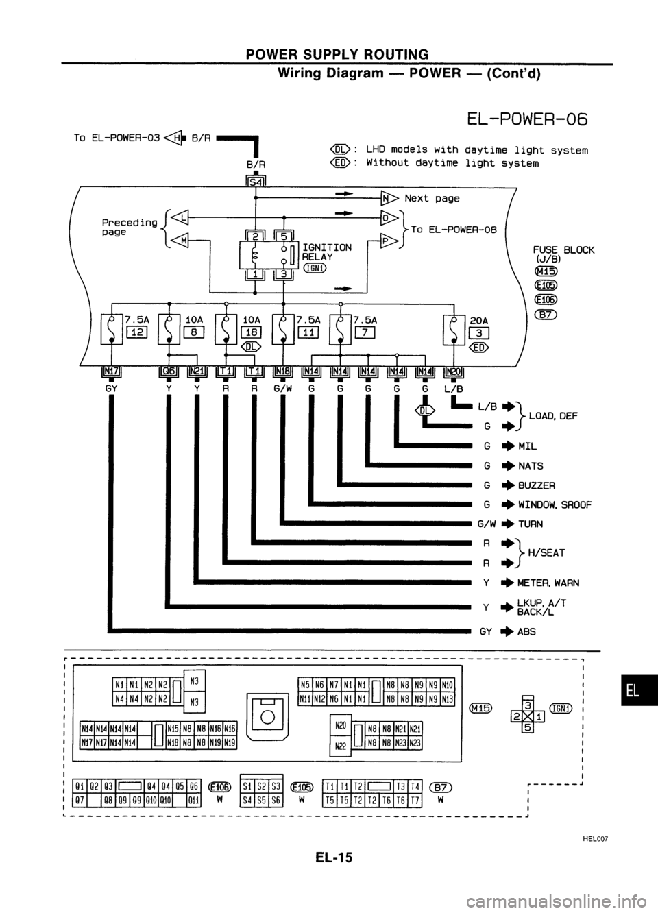
Wiring Diagram -POWER -(Coni' d)
EL-POWER-06
r-----------------------------------------------------------,
•
FUSE
BLOCK
(JIB)
(E105)
(f106)
@)
+
(IGNl)
2 1
5
20A
m
@)
G GLIB
t.=
L~B:} LOAD, DEF
G •MIL
G •NATS
G •BUZZER
G •WINDOW, SROOF
G/W •
TURN
: :} H/SEAT
Y •METER, WARN
Y •LKUP, AIT
BACK!L
GY •ABS
p
G G
-
@:
LHDmodels withdaytime lightsystem
@:
Without daytime lightsystem
R
G/W
G
R
Y
~
Y
Preceding
{L
page
To
EL-POWER-03 ~BIR--,
BIR
Is~1
----------------------------------------------------~
HEL007
EL-15
Page 391 of 1701
POWERSUPPLY ROUTING
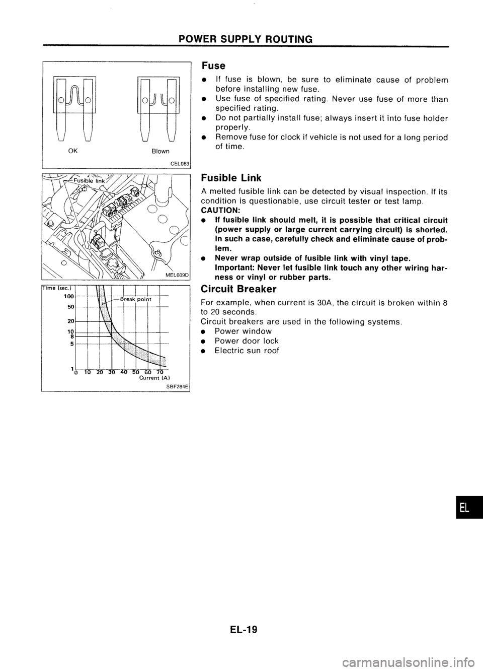
OK BlownFuse
• Iffuse isblown, besure toeliminate causeofproblem
before installing newfuse.
• Use fuse ofspecified rating.Neverusefuse ofmore than
specified rating.
• Donot partially installfuse;always insertitinto fuse holder
properly.
• Remove fuseforclock ifvehicle isnot used foralong period
of time.
ime (sec.)
100
50
20
10
8
5
CEL083
Fusible Link
A melted fusible linkcan bedetected byvisual inspection.
If
its
condition isquestionable, usecircuit testerortest lamp.
CAUTION:
• Iffusible linkshould melt,itis possible thatcritical circuit
(power supplyorlarge current carrying circuit)isshorted.
In such acase, carefully checkandeliminate causeofprob-
lem.
• Never wrapoutside offusible linkwith vinyl tape.
Important: Neverletfusible linktouch anyother wiring har-
ness orvinyl orrubber parts.
Circuit Breaker
For example, whencurrent is30A, thecircuit isbroken within8
to 20 seconds.
Circuit breakers areused inthe following systems.
• Power window
• Power doorlock
• Electric sunroof
SBF284E
EL-19
•
Page 394 of 1701
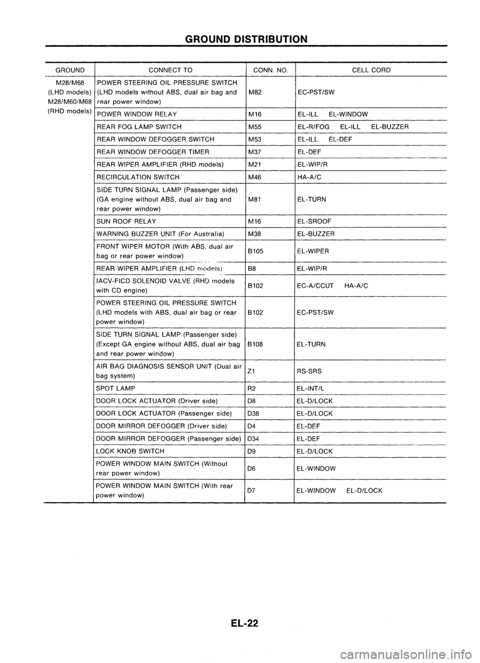
GROUNDDISTRIBUTION
GROUND CONNECT
TO CONN.NO.
CELLCORD
M28/M68
POWERSTEERING OILPRESSURE SWITCH
(LHD models) (LHDmodels withoutA8S,dualairbag and M82 EC-PST/SW
M28/M60/M68
rearpower window)
(RHD models)
POWERWINDOW RELAY
M16EL-ILLEL-WINDOW
REAR FOGLAMP SWITCH M55EL-R/FOGEL-ILLEL-8UZZER
REAR WINDOW DEFOGGER SWITCH M53EL-ILLEL-DEF
REAR WINDOW DEFOGGER TIMER M37EL-DEF
REAR WIPER AMPLIFIER (RHDmodels) M21EL-WIP/R
RECIRCULATION SWITCH M46HA-A/C
SIDE TURN SIGNAL LAMP(Passenger side)
(GA engine without A8S,dualairbag and M81 EL-TURN
rear power window)
SUN ROOF RELAY M16EL-SROOF
WARNING 8UZZERUNIT(ForAustralia)
M38EL-8UZZER
FRONT WIPERMOTOR (WithA8S,dualair
8105 EL-WIPER
bag orrear power window)
-_._-
-
REAR WIPER AMPLIFIER (LHDmodelsl 88EL-WIP/R
0-
IACV-FICD SOLENOID VALVE(RHDmodels
8102 EC-A/CCUTHA-A/C
with CDengine)
POWER STEERING OILPRESSURE SWITCH
(LHD models withASS, dualairbag orrear 8102 EC-PST/SW
power window)
SIDE TURN SIGNAL LAMP(Passenger side)
(Except GAengine without A8S,dualairbag 8108 EL-TURN
and rear power window)
AIR 8AG DIAGNOSIS SENSORUNIT(Dual air
Z1 RS-SRS
bag system)
SPOT LAMP
R2EL-INT/L
DOOR LOCKACTUATOR (Driverside)
D8 EL-D/LOCK
DOOR LOCKACTUATOR (Passengerside)
D38 EL-D/LOCK
DOOR MIRROR DEFOGGER (Driverside)
D4 EL-DEF
DOOR MIRROR DEFOGGER (Passengerside)
D34 EL-DEF
LOCK KN08 SWITCH
D9EL-D/LOCK
POWER WINDOW MAINSWITCH (Without
D6 EL-WINDOW
rear power window)
POWER WINDOW MAINSWITCH (Withrear
D7 EL-WINDOW EL-D/LOCK
power window)
EL-22
Page 494 of 1701
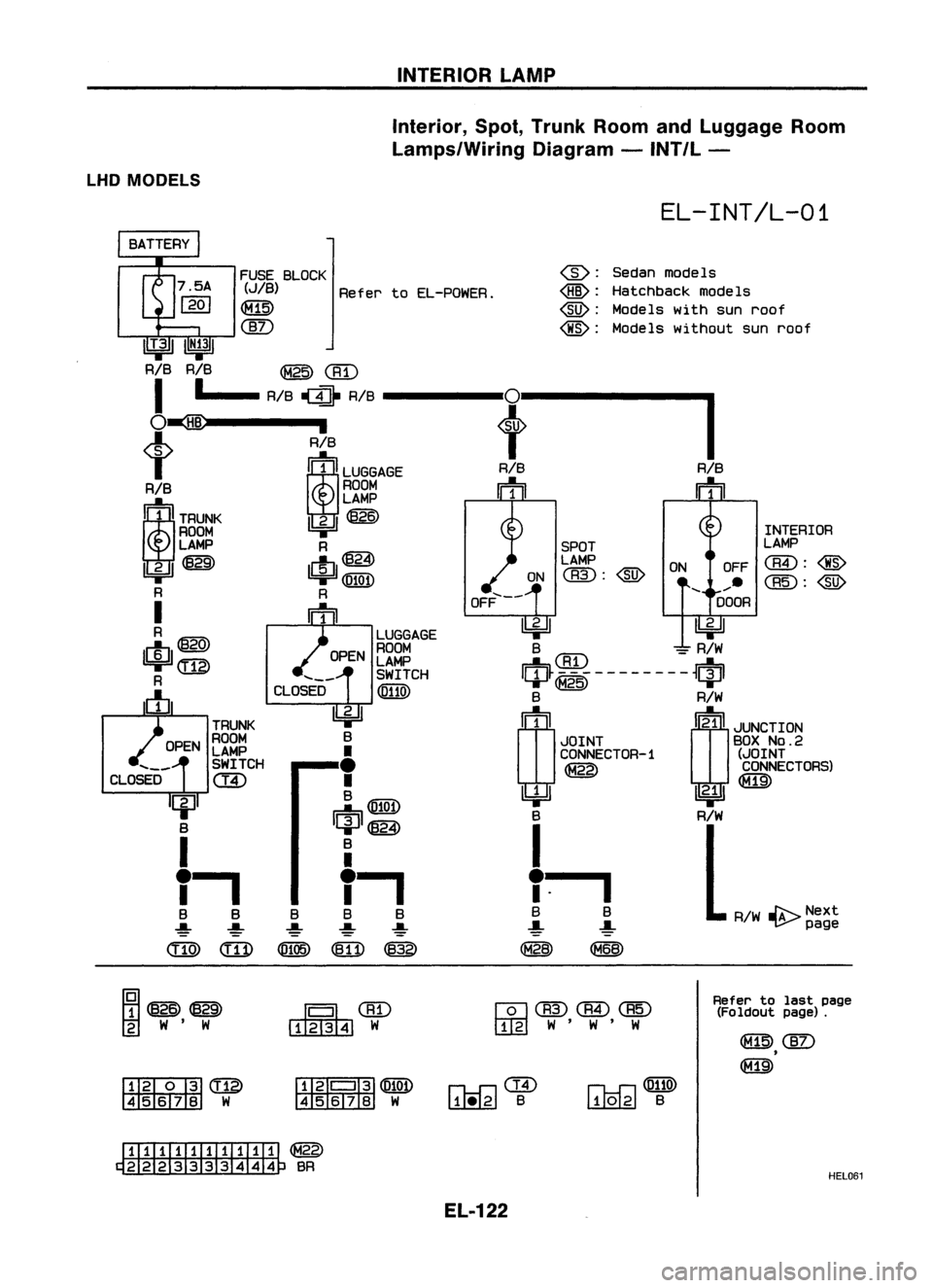
INTERIORLAMP
Interior, Spot,Trunk RoomandLuggage Room
Lamps/Wiring Diagram-INT/L -
LHD MODELS
EL-INT/L-01
FUSE BLOCK
(JIB)
RefertoEL-POWER.
~
@)
@:
Sedanmodels
@:
Hatchback modeIs
@:
Models withsunroof
@:
Models without sunroof
IIT.311
IN;31
RIB RIB
@@)
I
•
RIB
1II1}
RIB
0
I
O~
,
t
t
RIB
i~iLUGGAGE
RIB
RIB
RIB ROOM
m m
1~lrnu~
LAMP
~~
ROOM INTERIOR
LAMP R SPOTLAMP
lbi=Jl~
c!J@}
LAMP
ONOFF
aID:@
1bi=Jl@Q!)
ON
<:BID:
@)
......
R R
OFF.....--
DOOR
I
m
~~
R
LUGGAGE
$@
OPENROOM
B
CBD
=
R/W
LAMP
(ill)
SWITCH
IQP~~i~--------~qpl
R
CLOSED
@llID
c!J
B
R/W
~
rn(!)
JLNCTION
TRUNK
ROOM B
JOINTBOX
No.2
LAMP
•
CONNECTOR-1
(JOINT
SWITCH
•
CONNECTORS)
CLOSED
c::ID
•
~
B
~
m@W
~@)
B
R/W
I
B
I
r.
•
I
I
.
B BB B
B
R/W~Next
-!- -!--!-
-!-
-!-
page
<:ITID
(ill)
(Ql05)
~
@
~~
~CID
~W
wCBID(@@
rn::g]
W'W'W
~~~
~ W
I
W
I:illliTI]
@
~W
fHiI'
II~@W
4567B W
rh-f:l@
~ B
n.o-r:l@llID
LUQ.LgJ
B
Refer
tolast page
(Foldout page).
ITIillIITillIII
~BR
EL-122 HEL061
Page 496 of 1701
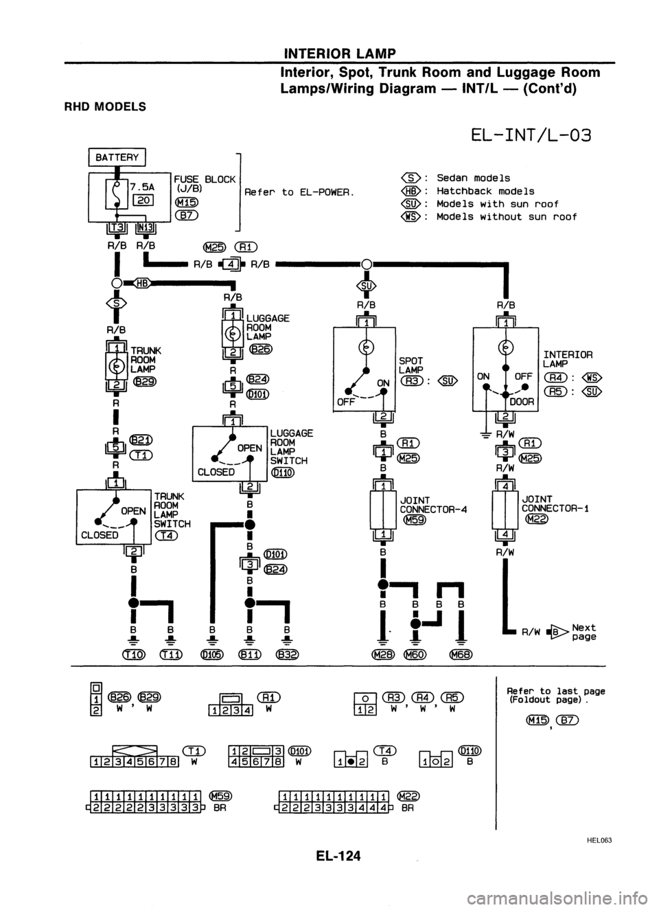
INTERIORLAMP
Interior, Spot,Trunk RoomandLuggage Room
Lamps/Wiring Diagram-INT/L -(Cant' d)
RHD MODELS
EL-INT/L-03
FUSE BLOCK
(JIB) RefertoEL-POWER.
~
CID
@:
Sedan modeIs
<@>:
Hatchback models
@:
Models withsunroof
@:
Models without sunroof
IIT.31
IIN~31
RIB RIB
~CRD
I
•
RIB
~ RIB
0
O~ ,
+
t
RIB
iLUGGAGE
RIB
IFh
RIB ROOM
1~ITRU~
LAMP
lbi=JI~
ROOM SPOT
LAMP R LAMP
U:jJI~
c!:I~
ON
aID:
@
1biJI@QD
OFF.....--
R R
I
n=h
~
R LUGGAGEB
c!J@
OPENROOM
m
CRD
I!:iJIcm
LAMP
qJ~
SWITCH
R
CLOSED
@llQ)
B
dJ
~
~
TRUNK
JOINT
ROOM B
.CONNECTOR-4
LAMP
•
~
SWITCH
•
CLOSED
@
•
4=ll
B
m@QD
B
[jJ~
I
B
,...,
n
I
f.
B
BBB
1-
I.J
J
B
B
B
!
~ ~~
('[@
@
(0105)
m
@
~
@
~
~@~
~QID
~am@)(][)
2 W' W
1234 W 1
2 W' W' W
~
RIB
IFh
INTERIOR
LAMP
ON OFF
C8!):
@
..... (][): @
DOOR
~
=
R/W
rnA'\
r=:b\..B.1..l
1[jJ1~
R/W
(1)
4
JOINT
CONNECTOR-1
~
~
R/W
R/W
..sa--.
Next
~page
Refer tolast page
(Foldout page).
I:HiII
I
Iii]
(O101)
45678 W
rk-OCffi
lli!.@
B
n-.,....c,
(0110)
l..!..l2@ B
ITIII:illITIIIT
@
~BR
ITIII:illITIIIT
~
~ BR
EL-124 HEL063
Page 596 of 1701
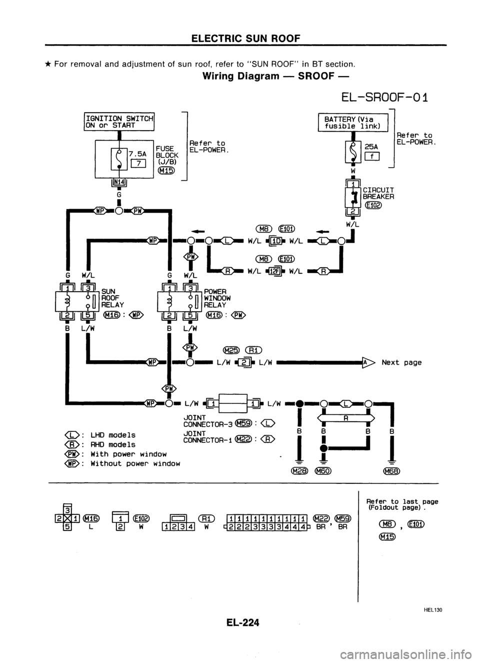
ELECTRICSUNROOF
*
For removal andadjustment ofsun roof, referto"SUN ROOF" in8T section.
Wiring Diagram -SROOF -
EL-SROOF-01
Referto
EL-POWER.
Refer to
EL-POWER.
PH
FUSE
7.5A BLOCK
m
(J/B)
CM15)
HP
IGNITION
SWITCH
ON or START
W
~1
CIRCUIT
BREAKER
([102)
~
.... CHID~ ....
W/L
I ~
-O-o~
W/L~ W/L
-ee-OJ
+
I
QID
lElQj)
I
G W!L GW/L ~ W!L~ W/L~
II:
t
I~II
SUN
II!"~II
POWER
n
ROOF
n
WINDOW
U
RELAY
U
RELAY
U:;JJ
Ibi=JI ~:
@
U:;JJ
Ibj:JJ ~:
@
B L/W BL/W
I ~
@CB"D
.----.~ -0-
L/W
(fi
L/W
--------B:>
Nextpage
HP
PH
0-
L/W~__
j1}
L/W
-.-O~O~
JOINT
I
<:
R
:>
CONNECTOR-3 ~:
models JOINT B
B BB
CONNECTOR-1 ~:
1
I
~
1
@:
RHOmodels
•
@:
Withpower window
!
@:
Without powerwindow
~
<8W
Refer tolast page
(Foldout page).
----'G2L
CBD
I1ITITIillIillI ~~
~W ~BR'BR
HEL130
EL-224