wheel NISSAN ALMERA N15 1995 Workshop Manual
[x] Cancel search | Manufacturer: NISSAN, Model Year: 1995, Model line: ALMERA N15, Model: NISSAN ALMERA N15 1995Pages: 1701, PDF Size: 82.27 MB
Page 345 of 1701

Note
Note Clean sensor fixing
portion, orreplace sen-
sor.
NG
OK
OK
Check clearance betweensensorand
rotor.
Clearance: Front0.1 -1.1
mm
(0.004 .0.043 in)
Rear 0.1 -1.1 mm
(0.004 -0.043 in)
WHEEL
SENSOR MECHANICAL CHECK
NGAdjust tirepressure or
replace tire(s).
Check forinflation pressure, wearand
size ofeach tire.
Note
Note Check wheelbearing axialendplay.
m
"Note
TROUBLE
DIAGNOSES
Diagnostic Procedure4(Conl'd)
@
SBR069C
\
\ Rotor
\\ Sensor
)6
Feeler gauge
)I
OK
Note Check sensor rotorforteeth damage.
NG
Note
Replace sensorrotor.
OK
Check control unitpinterminals for
damage orthe connection ofcontrol
unit harness connector.
Reconnect controlunitharness connec-
tor. Then retest.
Note:
Wheel position should •••
be distinguished by
code
No.except code
No. 18(sensor rotor).
BR-75
Page 352 of 1701

TROUBLEDIAGNOSES
Diagnostic Procedure8
CONTROL UNIT
(Malfunction codeNo.71)
Carry outself-diagnosis aftererasing
self-diagnostic results,BR-56.
Does warning lampindicate codeNo.
71 again?
No
Inspect thesystem according tothe
code No. Yes
Replace controlunit.
Brake pedal Diagnostic
Procedure9
SYMPTOM: Pedalvibration andnoise
No
Does thesymptom appearwhenelectri-
SAT797A
calequipment switches(suchashead-
lamp) areoperated?
1.
Apply brake.
2. Start engine.
3. Does thesymptom appearonlywhen
engine isstarted?
No
Yes
Check wheelsensor shieldgrou.nd
secured withcontrol unitmounting bolt.
Refer toBR-41. Yes
Carryoutself-diagnosis.
Refer toBR-53 (Europe)
or BR-56 (Except
Europe).
Go to
Ii1
inDiagnostic
Procedure 11,BR-83.
OK
Check control unitpinterminals for
damage orthe connection ofcontrol
unit harness connector.
Reconnect controlunitharness connec-
tor. Then retest.
Note: ABSmayoperate andcause vibration underanyofthe
following conditions.
• Applying brakegradually whenshifting oroperating clutch.
• Low friction (slippery) road.
• High speed cornering.
• Driving overbumps andpotholes.
• Engine speedisover 5,000 rpmwith vehicle stopped.
BR-82
Page 353 of 1701

TROUBLEDIAGNOSES
Diagnostic Procedure10
SYMPTOM: Longstopping distance
Disconnect ABSrelay box6-pin connec- No
tor and check whether stopping dis-
tance isstill long.
Perform Preliminary Checkandair
bleeding. Go
to
IiJ
inDiagnostic
Procedure 11.SR-83.
Note: Stopping distancemaybelarger thanvehicles without
ABS when roadcondition isslippery.
Diagnostic Procedure11
SYMPTOM: Unexpected pedalaction
m
Check brakepedalstroke. Isstroke
excessively
large?
No
Disconnect ASSrelay box6-pin connec-
tor and check whether brakeiseffec-
SBR540A tive.
Yes
Ensure warning lampremains offwhile
driving.
OK
CHECK WHEEL SENSOR.
1. Check wheelsensor connector for
terminal damageorloose connec-
tion.
2. Perform wheelsensor mechanical
check. Refer to
IiJ
inDiagnostic Procedure
4, BR-75.
OK
Check control unitpinterminals for
damage orthe connection ofcontrol
unit harness connector.
Reconnect controlunitharness connec-
tor. Then retest.
BR-83
Yes
Perform Preliminary
Check. refertoSR-65.
Perform Preliminary
Check. refertoSR-65.
Carry outself-diagnosis.
Refer toBR-53 (Europe)
or SR-56 (Except
Europe).
Repair.
•
Page 354 of 1701
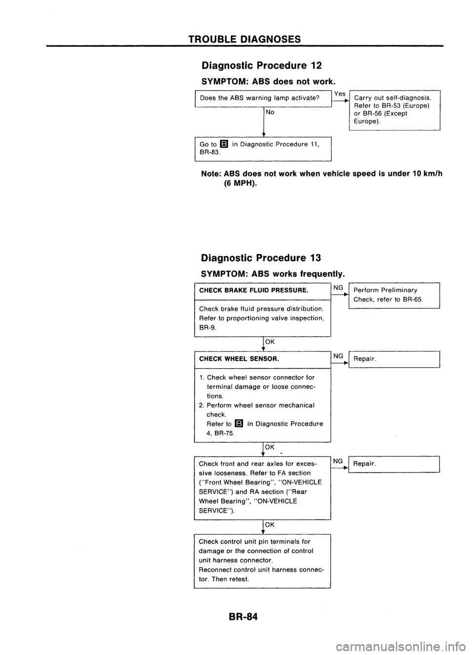
TROUBLEDIAGNOSES
Diagnostic Procedure12
SYMPTOM: ASSdoes notwork.
Does theABS warning lampactivate?
No
Go to
Ii)
inDiagnostic Procedure11,
BR-83.
Yes
Carryoutself-diagnosis.
Refer toBR-53 (Europe)
or BR-55 (Except
Europe).
Note: ABSdoes notwork when vehicle speedisunder 10km/h
(6 MPH).
Diagnostic Procedure13
SYMPTOM: ASSworks frequently.
CHECK BRAKEFLUIDPRESSURE.
Check brakefluidpressure distribution.
Refer toproportioning valveinspection,
BR-9.
OK
CHECK WHEEL SENSOR.
1. Check wheelsensor connector for
terminal damage orloose connec-
tions.
2. Perform wheelsensor mechanical
check.
Refer to
Ii)
inDiagnostic Procedure
4, BR-75.
OK
Check frontandrear axles forexces-
sive looseness. RefertoFA section
("Front WheelBearing", "ON-VEHICLE
SERVICE") andRAsection ("Rear
Wheel Bearing", "ON-VEHICLE
SERVICE").
OK
Check control unitpinterminals for
damage orthe connection ofcontrol
unit harness connector.
Reconnect controlunitharness connec-
tor. Then retest.
BR-84 NG
NG
NG
Perform
Preliminary
Check, refertoBR-55.
Repair.
Repair.
Page 355 of 1701
TROUBLEDIAGNOSES
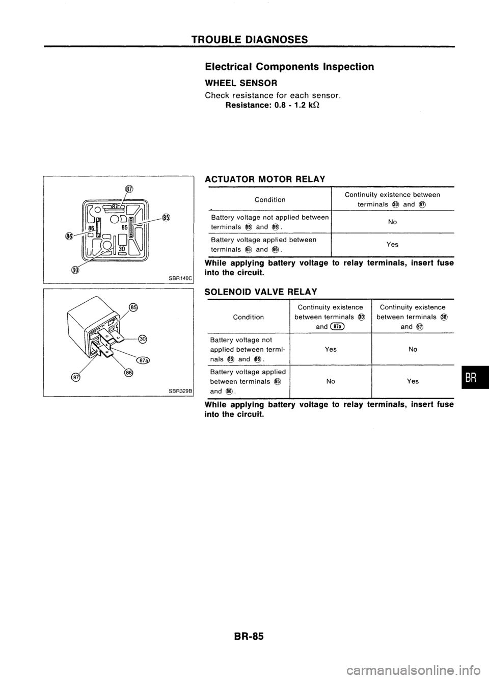
Electrical Components Inspection
WHEEL SENSOR
Check resistance foreach sensor.
Resistance: 0.8-1.2 kQ
ACTUATOR MOTORRELAY
While applying batteryvoltage torelay terminals, insertfuse
into thecircuit.
Condition
Battery voltage notapplied between
terminals
@
and
@.
Battery voltage applied between
terminals
@
and
@.
SBR140C
Continuity
existencebetween
terminals
@
and
@
No
Yes
SBR329B SOLENOID
VALVERELAY
Continuity existence Continuityexistence
Condition between
terminals
@
between terminals
@
and@ and
@
Battery voltage not
applied between termi- Yes
No
nals
@
and
@.
Battery voltage applied
between terminals
@
No Yes
and
@.
While applying batteryvoltage torelay terminals, insertfuse
into thecircuit.
BR-85
•
Page 359 of 1701
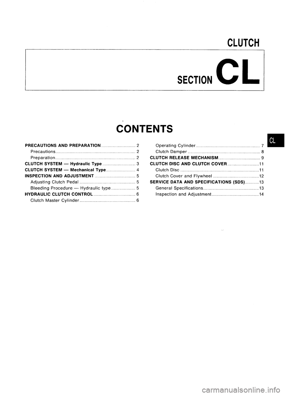
CLUTCH
SECTION
CL
CONTENTS
PRECAUTIONS ANDPREPARATION 2
Precautions 2
Preparation 2
CLUTCH SYSTEM-Hydraulic Type
3
CLUTCH SYSTEM-Mechanical Type 4
INSPECTION ANDADJUSTMENT
5
Adjusting ClutchPedal 5
Bleeding Procedure -Hydraulic type 5
HYDRAULIC CLUTCHCONTROL.. 6
Clutch Master Cylinder 6Operating
Cylinder 7
Clutch Damper 8
CLUTCH RELEASE MECHANiSM 9
CLUTCH DISCANDCLUTCH COVER 11
Clutch Disc 11
Clutch CoverandFlywheel 12
SERVICE DATAANDSPECIFICATIONS (SDS)13
General Specifications 13
Inspection andAdjustment 14
•
Page 370 of 1701
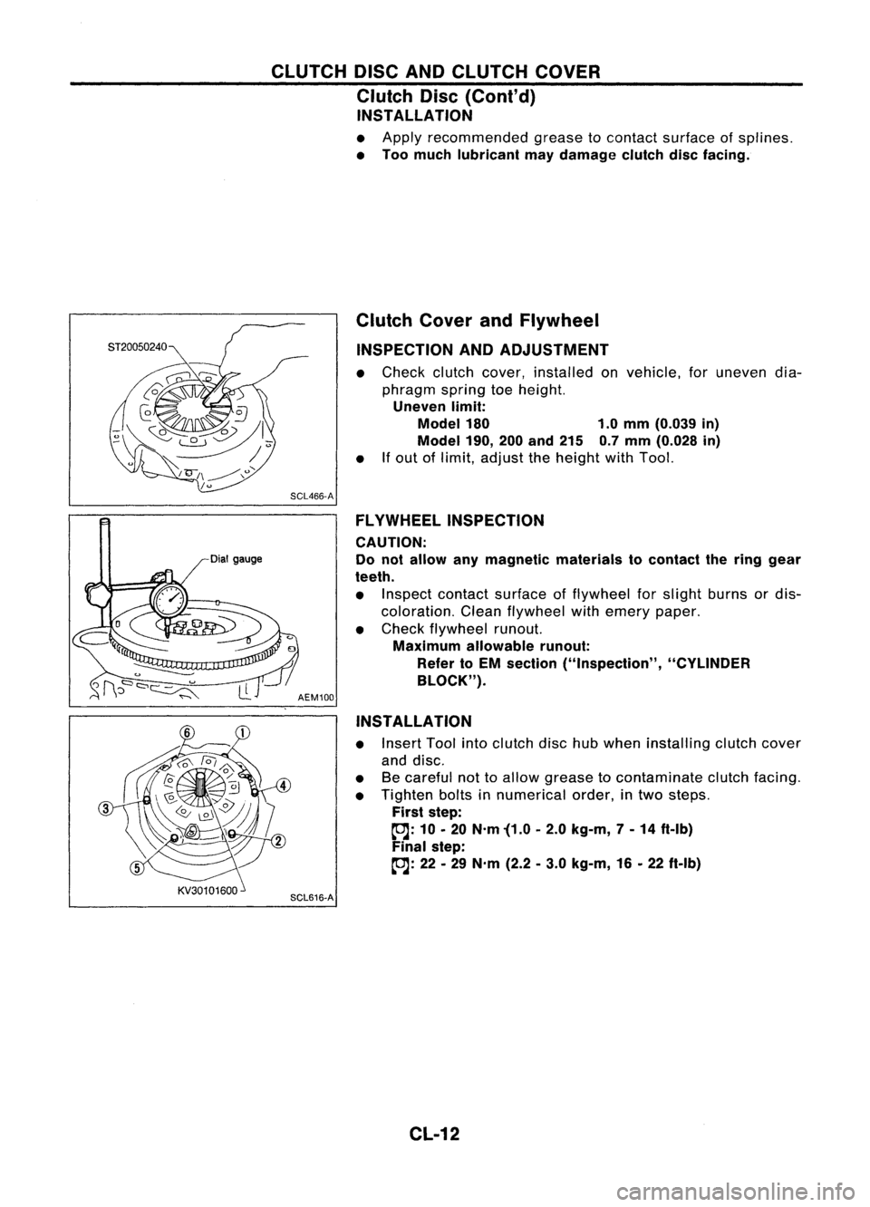
CLUTCHDISCANDCLUTCH COVER
Clutch Disc(Cont'd)
INSTALLATION
• Apply recommended greasetocontact surface ofsplines.
• Too much lubricant maydamage clutchdiscfacing.
Dial gauge Clutch
CoverandFlywheel
INSPECTION ANDADJUSTMENT
• Check clutchcover, installed onvehicle, foruneven dia-
phragm springtoeheight.
Uneven limit:
Model 180 1.0mm (0.039 in)
Model 190,
200and 215 0.7mm (0.028 in)
• Ifout oflimit, adjust theheight withTool.
SCL466-A FLYWHEEL INSPECTION
CAUTION:
Do not allow anymagnetic materials tocontact thering gear
teeth.
• Inspect contact surface offlywheel forslight burns ordis-
coloration. Cleanflywheel withemery paper.
• Check flywheel runout.
Maximum allowable runout:
Refer toEM section ("Inspection", "CYLINDER
BLOCK").
AEM100
INSTALLATION
• Insert Toolintoclutch dischubwhen installing clutchcover
and disc.
• Becareful nottoallow grease tocontaminate clutchfacing.
• Tighten boltsinnumerical order,intwo steps.
First step:
~: 10•20 N'm '(1.0 •2.0 kg-m, 7-14 ft-Ib)
Final step:
~: 22•29 N'm (2.2•3.0 kg-m, 16•22 ft-Ib)
SCL616-A
CL-12
Page 376 of 1701
PRECAUTIONS
Supplemental RestraintSystem(SRS)"AIR
BAG" (DualAirBag System)
The Supplemental RestraintSystem"AirBag", usedalong withaseat belt,helps toreduce therisk or
severity ofinjury tothe driver andfront passenger inafrontal collision. TheSupplemental Restraint
System consists ofair bag modules (locatedinthe center ofthe steering wheelandonthe instrument
panel onthe passenger side),adiagnosis sensorunit,warning lamp,wiring harness andspiral cable.
Information necessarytoservice thesystem safelyisincluded inthe
RSsection
ofthis Service Manual.
WARNING:
• Toavoid rendering theSRS inoperative, whichcouldincrease therisk ofpersonal injuryordeath
in the event ofacollision whichwould resultinair bag inflation, allmaintenance mustbeperformed
by an authorized NISSANdealer.
• Improper maintenance, includingincorrectremovalandinstallation ofthe SRS, canlead topersonal
injury caused byunintentional activationofthe system.
• Donot use electrical testequipment onany circuit related tothe SRS unless instructed tointhis
Service Manual. SRSwiring harnesses arecovered withyellow insulation eitherjustbefore the
harness connectors orfor the complete harness,foreasy identification.
Supplemental RestraintSystem(SRS)"AIR
BAG" (Single AirBag System)
The Supplemental RestraintSystem"AirBag", usedalong withaseat belt,helps toreduce therisk or
severity ofinjury tothe driver inafrontal collision. TheSupplemental RestraintSystemconsists ofan
air bag module (located inthe center ofthe steering wheel),adiagnosis sensorunit,warning lampand
spiral cable. Information necessarytoservice thesystem safelyisincluded inthe
RSsection
ofthis
Service Manual.
WARNING: • Toavoid rendering theSRS inoperative, whichcouldincrease therisk ofpersonal injuryordeath
in the event ofacollision whichwould resultinair bag inflation, allmaintenance mustbeperformed
by an authorized NISSANdealer.
• Improper maintenance, includingincorrectremovalandinstallation ofthe SRS, canlead topersonal
injury caused byunintentional activationofthe system.
• Donot use electrical testequipment onany circuit related tothe SRS.
EL-4
Page 396 of 1701

GROUNDDISTRIBUTION
GROUND CONNECT
TO CONN.
NO. CELL
CORD
B11/B32 LUGGAGEROOMLAMPSWITCH 0110
EL-INT/L
(Sedan) REARCOMBINATION LAMPLH(BACK-UP) 0103 EL-BACK/L
B11/B32/D105
(Hatchback) REAR
COMBINATION LAMPLH(REAR FOG)
0103 EL-R/FOG
(LHD Hatchback modelsforEurope)
REAR COMBINATION LAMPLH(TAIL)
0103 EL-TAILIL
(Hatchback exceptforEurope andAustralia)
REAR COMBINATION LAMPRH(BACK-UP) 0111 EL-BACK/L
REAR COMBINATION LAMPRH(REAR FOG)
0111 EL-R/FOG
(RHO Hatchback modelsforEurope)
REAR COMBINATION LAMPRH(TAIL)
0111 EL-TAILIL
(Hatchback exceptforEurope andAustralia)
T10/T11 HIGH-MOUNTED STOPLAMP (Sedan) T6EL-STOP/L
LICENSE PLATELAMPLH(Sedan) T5EL-TAILIL
LICENSE PLATELAMPRH(Sedan) T7EL-TAILIL
REAR COMBINATION LAMPLH(BACK-UP)
T3 EL-BACK/L
(LHD Sedan models)
REAR COMBINATION LAMPLH(REAR FOG)
T3 EL-R/FOG
(Sedan)
REAR COMBINATION LAMPLH(TAIL AND
T2 EL-TAILIL
EL-STOP/L
STOP) (Sedan)
REAR COMBINATION LAMPLH(TAIL)
T3 EL-TAILIL
(Sedan exceptforEurope andAustralia)
REAR COMBINATION LAMPLH(TURN SIG-
T2 EL-TURN
NAL) (Sedan)
REAR COMBINATION LAMPRH(BACK-UP)
TB EL-BACK/L
(Sedan)
REAR COMBINATION LAMPRH(REAR FOG)
TB
EL-R/FOG
(RHO Sedan models)
REAR COMBINATION LAMPRH(TAIL AND
T9 EL-TAILILEL-STOP/L
STOP) (Sedan)
REAR COMBINATION LAMPRH(TAIL)
TB
EL-TAILIL
(Sedan exceptforEurope andAustralia)
REAR COMBINATION LAMPRH(TURN SIG-
T9 EL-TAILIL
NAL) (Sedan)
.
TRUNK ROOMLAMPSWITCH T4
EL-INT/L
B110 SHIELDWIRE(WHEEL SPEEDSENSOR
E4BR-ABS
FRONT LH)(LHD models)
SHIELD WIRE(WHEEL SPEEDSENSOR
E11BR-ABS
FRONT RH)(RHO models)
SHIELD WIRE(WHEEL SPEEDSENSOR
B106BR-ABS
FRONT LH)(RHO models)
SHIELD WIRE(WHEEL SPEEDSENSOR
B107BR-ABS
FRONT RH)(LHD models)
B112 ABSCONTROL UNIT B111BR-ABS
ABS RELAY BOX B104BR-ABS
B204 REARWINDOW DEFOGGER B203EL-DEF
EL-24
Page 683 of 1701
FRONTAXLE
&
FRONT SUSPENSION
SECTION
FA
CONTENTS
PRECAUTIONS ANDPREPARATION 2
Precautions 2
Special ServiceTools 2
Commercial ServiceTools 3
FRONT SUSPENSION SySTEM 4
ON-VEHICLE SERVICE
5
Front AxleandFront Suspension Parts 5
Front Wheel Bearing 5
Front Wheel Alignment.. 6
Drive Shaft 7FRONT
AXLE 8
Wheel HubandKnuckle 8
Drive Shaft 12
FRONT SUSPENSION 24
Coil Spring andStrut Assembly 25
Stabilizer Bar 26
Transverse LinkandLower BallJoint.. 27•
SERVICE DATAANDSPECIFICATIONS (SDS)29
General Specifications 29
Inspection andAdjustment 29