NISSAN ALMERA N15 1995 Service Manual
Manufacturer: NISSAN, Model Year: 1995, Model line: ALMERA N15, Model: NISSAN ALMERA N15 1995Pages: 1701, PDF Size: 82.27 MB
Page 931 of 1701
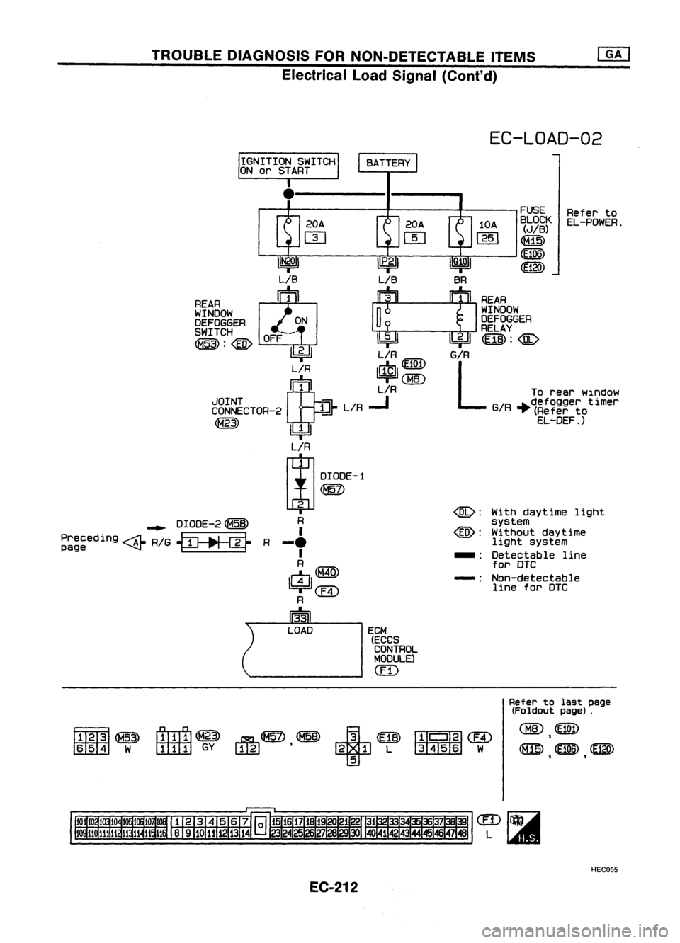
TROUBLEDIAGNOSIS FORNON-DETECTABLE ITEMS
Electrical LoadSignal (Cont'd)
EC-LOAD-02
Referto
EL-POWER.
FUSE
BLOCK
(JIB)
~
(106)
~120)
With daytime light
system
Without daytime
light system
Detectable line
for OTC
Non-detectable line forOTC
-:
-:
@:
@:
ECM (ECeS
CONTROL
MODULE)
(fD
.------
20A 20A10A
m [[]
1251
I
Pl'
IQ~OI
LIB BR
REAR ~1~
rn!
REAR
WINDOW
InI
WINDOW
DEFOGGER ONU ~~r~~GER
SWITCH OFF--
-1-i~'---I-i"""""l
m:@)
@:@
11211
.,=
L/R
G/R
L/R
IrJPl
m
CHID
~ L/R Torear window
~g~~~CTOR-2 ~L/R
..J
G/R
~~~~~~~e~otimer
@)
I.4=JI
EL-DEF .)
L/R
~ DIOOE-1
~
2
R
I
-.
I
R
m@
!!4Jl@
R
13'31
LOAD
~
OIOOE-2~
Preceding
---At-
RIG~
R
page ~
f1Till1~
1m
W
rrrITrl@
~~~+
m
(!IIII~
@
ITlIl]
GYW,gJ' 21L 345 6 W
5
Refer
tolast page
(Foldout page).
CHID
m
,
~ (106)@Q)
, ,
HEC055
EC-212
Page 932 of 1701
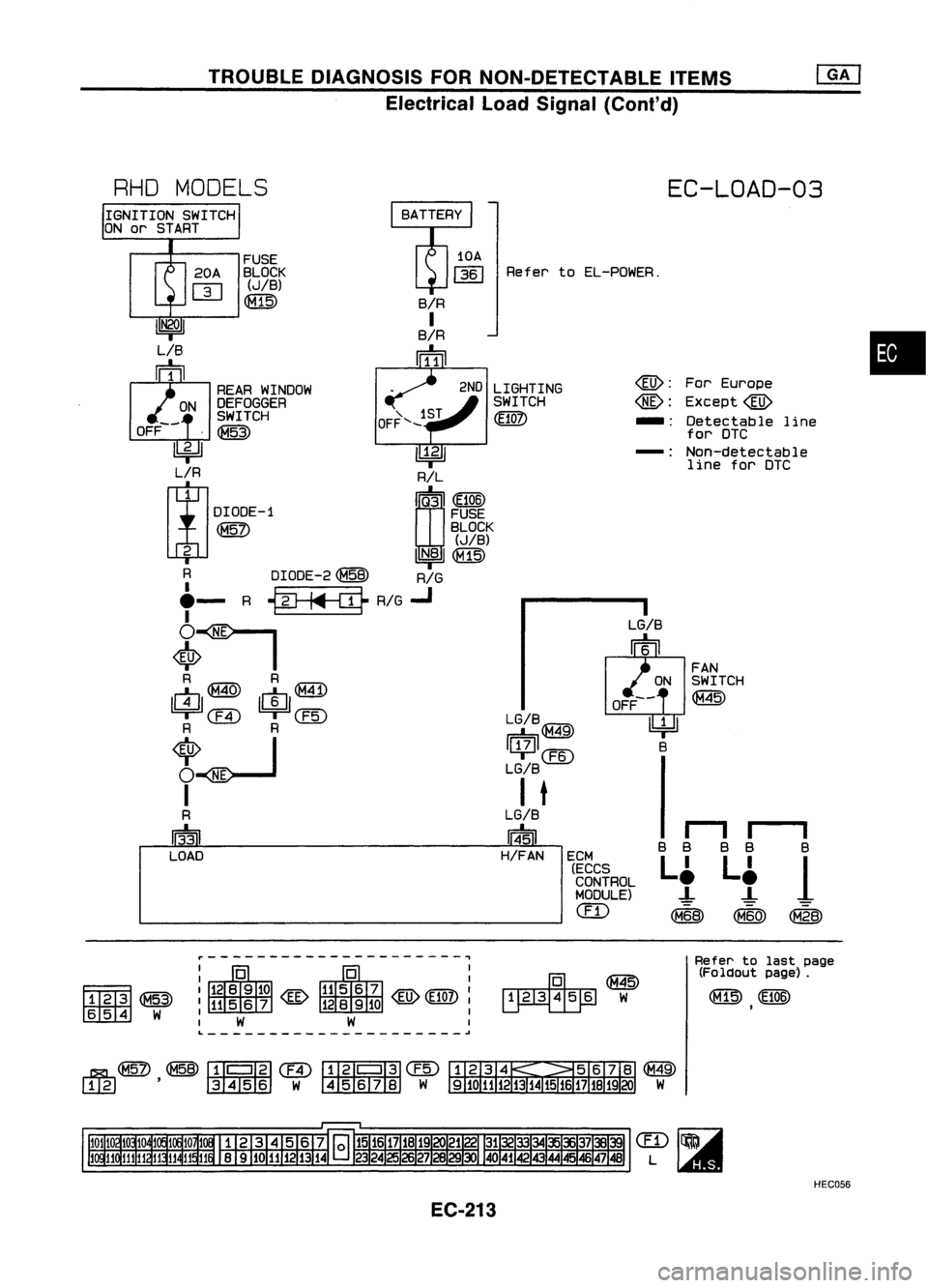
TROUBLEDIAGNOSIS FORNON-DETECTABLE ITEMS
Electrical LoadSignal (Cont'd)
RHO MODELS
EC-LOAD-03
•
For
Europe
Except@
Detectable line
for DTC
Non-detectable line forDTC
rI
II
B B
BB
B
L~ L~
1
-!- -!-
(M68) (M60)
CM28)
-:
@:
@:
-:
LG/B
~6
FAN
ON SWITCH
OFF-- ~
l4=!J
B
Refer
toEL-POWER.
LG/B
IGA"?i\
r=b~
IU/JI@
LG/B
I
t
LG/B
1@5J1
H/FAN
2ND
LIGHTING
SWITCH
(E10?)
FUSE
BLOCK
(JIB)
~
I
ECM(ECCS
CONTROL
MODULE)
(IT)
-------------------
~
LIB
~1
REARWINDOW
ON DEFOGGER
SWITCH
OFF-- ,~
~ ~
OO
L~R ~R:~~
DIODE-1 FUSE
~ BLOCK
(JIB)
2
UN.BI~
R DIODE-2~
RIG
e-
R
{#Jjf{I}
RIG
..J
6~
<$>
I
R R
rn~ rn~
~ em
I!4=lJ
@
R R
~ I
O~
I
R
IT3n
LOAD
F1Tffi~
rn:rn:rn
W
~---------------------~
~@
~w
Refer
tolast page
(Foldout page').
~ (E106)
,
L ~
HEC056
EC-213
Page 933 of 1701
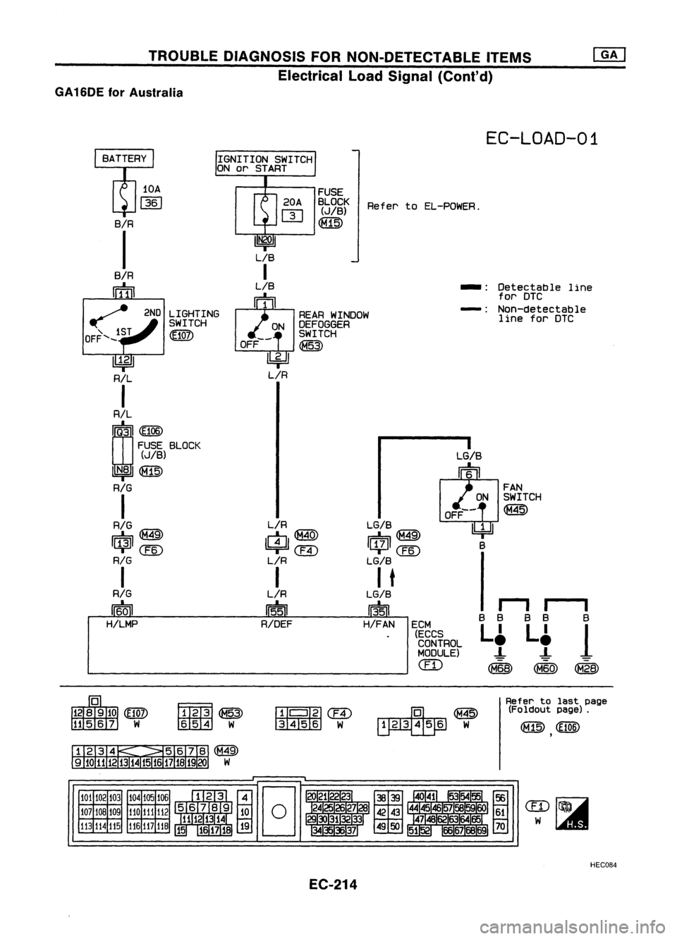
TROUBLEDIAGNOSIS FORNON-DETECTABLE ITEMS
Electrical LoadSignal (Cont'd)
GA 16DE forAustralia
EC-LOAD-01
I
B
1
@
B
B
L~
-!-
(M60)
Detectable
line
for DTC
Non-detectable line forDTC
B B
L~
-!-
~
-:
-:
LG/B
~6
FAN
ON SWITCH
OFF--
@
I4J
B
ECM (ECCS
CONTROL
MODULE)
em
LG/B
r::::b@
IlJlll
CEID
LGIB
I
t
LG/B
1351
H/FAN
LIR
I$I@
@
L/R
I
L/R
115'51
R/DEF
FUSE
20A BLOCK RefertoEL-POWER.
m
(JIB)
~
~
LIB
I
LIB
l1JJ
l
REARWINDOW
ON DEFOGGER
SWITCH
OFF-- ~
lbi=ll
L/R
2ND
LIGHTING
SWITCH
~
RIL
I
R/L
~Q'3
I
(EiOS)
FUSE BLOCK
(JIB)
IN181~
RIG
I
RIG
IU"ArI\
r=:b,~
'Uil'
CEID
RIG
I
RIG
~
H!LMP
lOA
1361
BIR
I
BIR
rrffil
~
OFF ...._1ST
~~
tiliIiI
W
lll'
III~ ~
3456 W
~@
~W
Refer
tolast page
(Foldout page).
101 102103
107 108109
113 114115 104
105 106
110 111 112
116
117
118
HEC084
EC-214
Page 934 of 1701
![NISSAN ALMERA N15 1995 Service Manual L,__
R_E_CO_R_D __
I
MEC212B
Ii]
*
MONITOR
*
NO FAIL
0
LOAD SIGNAL OFF
•
r-
(A)
INSPECTION
START
m
CHECK OVERALL FUNCTION-I. NG
Check rearwindow
1) Turn ignition switch"ON",
--- NISSAN ALMERA N15 1995 Service Manual L,__
R_E_CO_R_D __
I
MEC212B
Ii]
*
MONITOR
*
NO FAIL
0
LOAD SIGNAL OFF
•
r-
(A)
INSPECTION
START
m
CHECK OVERALL FUNCTION-I. NG
Check rearwindow
1) Turn ignition switch"ON",
---](/img/5/57349/w960_57349-933.png)
L,__
R_E_CO_R_D __
I
MEC212B
Ii]
*
MONITOR
*
NO FAIL
0
LOAD SIGNAL OFF
•
r-
(A)
INSPECTION
START
m
CHECK OVERALL FUNCTION-I. NG
Check rearwindow
1) Turn ignition switch"ON",
----+
defogger circuit.
00
2)
Check "LOAD SIGNAL" in
(Goto
I
Procedure A
I,)
"DATA MONITOR" modewith
CONSULT. Rear window defogger switch
is "ON": ON
Rear window defogger switch
.
is"OFF": OFF
OR
@
2)
Check voltage between ECM
terminal
@
or
@
and
ground underthefollowing
conditions.
Voltage:
Rear window defogger
switch is"ON".
Battery voltage
Rear window defogger
switch is"OFF".
Approximately OV
OK
Ii]
CHECK OVERALL FUNCTION-II. NG
Check lighting switchcir-
1) Turn rearwindow defogger switch
----+
cuit.
"OFF", (Goto
I
Proceduffil?J)
00
2)
Check "LOAD SIGNAL" in
"DATA MONITOR" modewith
CONSULT.
Lighting switchis"ON": ON
Lighting switchis"OFF": OFF
OR
@
2)
Turn ignition switch"OFF"
3) Check voltage between ECM
terminal
i@J
or
@
and
ground underthefollowing
cond itions.
Voltage: Lighting switchis"ON".
Battery voltage
Lighting switchis"OFF".
Approximately OV
SEF240R
SEF241R
SEF197R
OFF
*
NO FAIL
0
TROUBLE
DIAGNOSIS FORNON-DETECTABLE ITEMS
Electrical LoadSignal (Cont'd)
DIAGNOSTIC PROCEDURE
~15@a0
ECM
ECONNECTORII
33 55
~15~
ECM
E
CONNECTOR
II
45 35
~15~
ECM
€I'
CONNECTOR
II
33 60
*
MONITOR
LOAD SIGNAL
@:
ForAustralia
33 :Except forAustralia
@:
ForAustralia
45 ,
Except forAustralia
@:
ForAustralia
33 :
Except forAustralia
___
RE_C_O_R_D __
I
MEC212B
II
II
II
EC-215
Page 935 of 1701
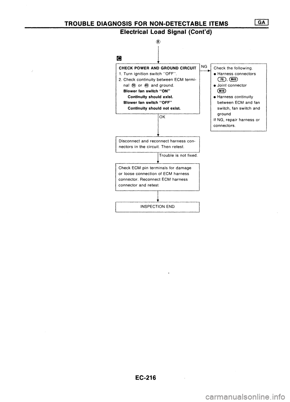
TROUBLEDIAGNOSIS FORNON-DETECTABLE ITEMS
Electrical LoadSignal (Cont'd)
@
CHECK POWER ANDGROUND CIRCUIT
1. Turn ignition switch"OFF".
2. Check continuity betweenECMtermi-
nal
@
or
@
and ground.
Blower fanswitch "ON"
Continuity shouldexist.
Blower fanswitch "OFF"
Continuity shouldnotexist.
OK
Disconnect andreconnect harnesscon-
nectors inthe circuit. Thenretest.
Trouble isnot fixed.
Check ECMpinterminals fordamage
or loose connection ofECM harness
connector. ReconnectECMharness
connector andretest
INSPECTION END
EC-216 NG
Check thefollowing.
• Harness connectors
QD,@
• Joint connector
@
• Harness continuity
between ECMandfan
switch, fanswitch and
ground
If NG, repair harness or
connectors.
Page 936 of 1701
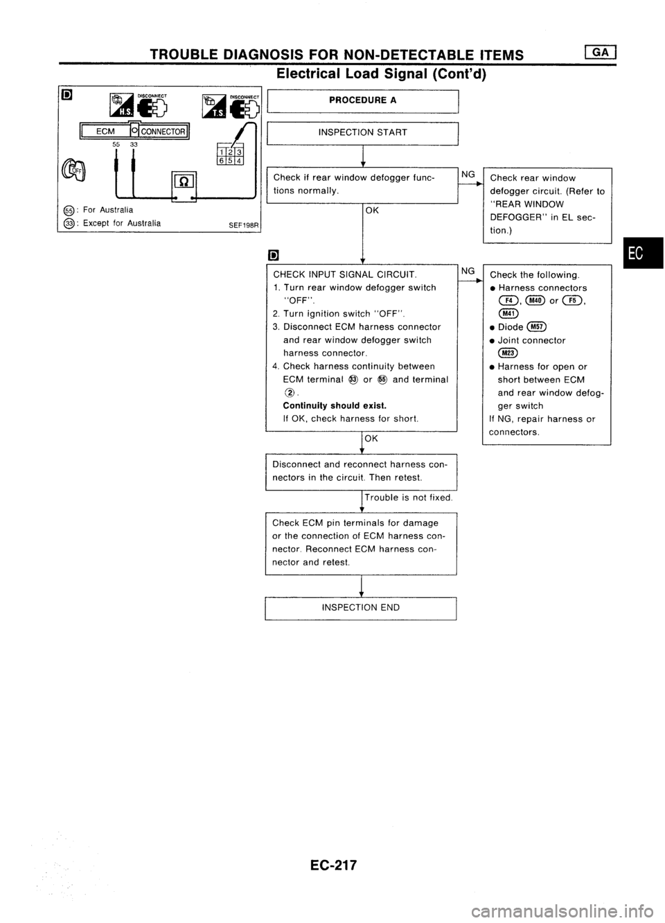
INSPECTIONSTART
TROUBLE
DIAGNOSIS FORNON-DETECTABLE ITEMS
Electrical LoadSignal (Cont'd)
~ 15 ~15
I
P_RO_CE_DU_RE_A _
ECM
ECONNECTOR
II
55 33
@:
ForAustralia
@:
Except forAustralia
SEF19SR
Check
ifrear window defogger func-
tions normally.
OK
I;J
CHECK INPUTSIGNAL CIRCUIT.
1. Turn rearwindow defogger switch
"OFF".
2. Turn ignition switch"OFF".
3. Disconnect ECMharness connector
and rear window defogger switch
harness connector.
4. Check harness continuity between
ECM terminal
@
or
@
and terminal
@.
Continuity shouldexist.
If OK, check harness forshort.
OK
Disconnect andreconnect harnesscon-
nectors inthe circuit. Thenretest.
Trouble isnot fixed.
Check ECMpinterminals fordamage
or the connection ofECM harness con-
nector. Reconnect ECMharness con-
nector andretest.
INSPECTION END
EC-217 NG
NG
Check
rearwindow
defogger circuit.(Referto
"REAR WINDOW
DEFOGGER" inEL sec-
tion.)
Check thefollowing.
• Harness connectors
@,@orQI),
@
• Diode@
• Joint connector
@
• Harness foropen or
short between ECM
and rear window defog-
ger switch
If NG, repair harness or
connectors.
•
Page 937 of 1701
TROUBLEDIAGNOSIS FORNON-DETECTABLE ITEMS
Electrical LoadSignal (Cont'd)
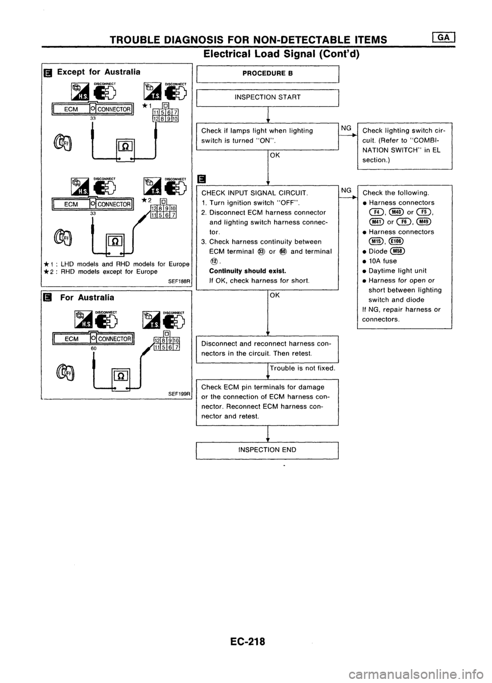
PROCEDURE B
INSPECTION START
Check iflamps lightwhen lighting NG
Check lighting switchcir-
switch isturned "ON".
-----..--..
cui!.(Refer to"COMBI-
OK NATION
SWITCH" inEL
section.)
Ii
CHECK INPUTSIGNAL CIRCUIT. NG
Check thefollowing.
1. Turn ignition switch"OFF".
-----..--..
•Harness connectors
2. Disconnect ECMharness connector CID,@or@,
and lighting switchharness connec- @orQD,@
tor. •
Harness connectors
3. Check harness continuity between
@,@ID
ECM terminal
@
or@ and terminal .Diode@
@. •10A fuse
Continuity shouldexist.
•
Daytime lightunit
If OK, check harness forshort. •
Harness foropen or
OK short
between lighting
switch anddiode
If
NG, repair harness or
connectors.
Disconnect andreconnect harnesscon-
nectors inthe circuit. Thenretest.
Trouble isnot fixed.
Check ECMpinterminals fordamage
or the connection ofECM harness con-
nector. Reconnect ECMharness con-
nector andretest.
INSPECTION END
SEF199R
~&5
~15
1='
=E=CM===IE[ CONNECTOR
II
60
SEF188R
~15
~i5
II
ECM
19"
CONNECTOR
II
33
*
1:LHD models andRHD models forEurope
*
2:RHD models exceptforEurope
II
Except forAustralia
I
~Io ~io----~
II
ECM E!'CONNECTOR
II
33
II
ForAustralia
EC-218
Page 938 of 1701
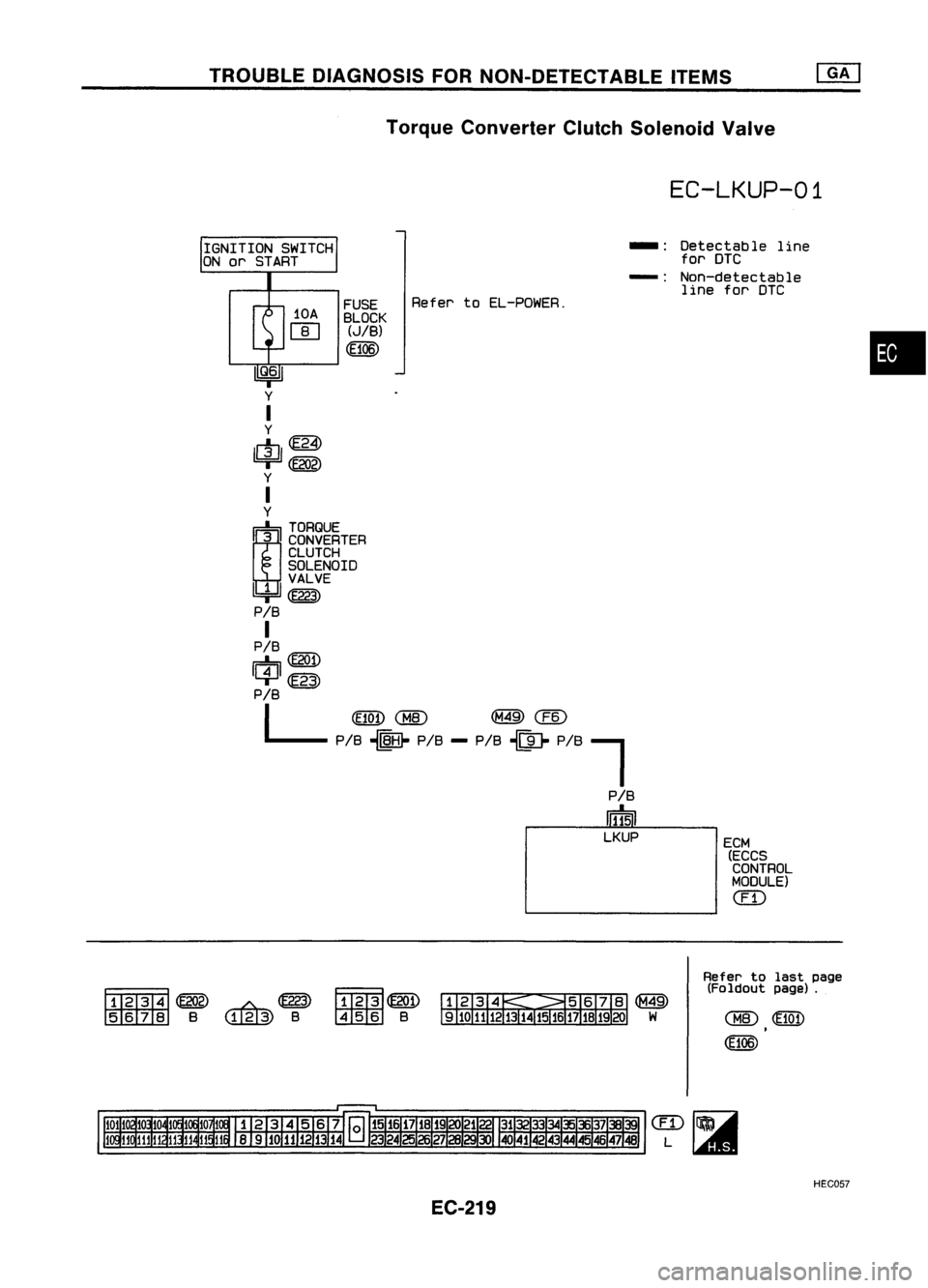
TROUBLEDIAGNOSIS FORNON-DETECTABLE ITEMS
Torque Converter ClutchSolenoid Valve
IQ.61
y
I
y
1l1J1
ffi
=r
(E202)
y
I
y
r::b,
TORQUE
~3 CONVERTER
CLUTCH
SOLENOID
II 111 VALVE
=r
(E223)
PIB
I
PIS
r::b,@i)
Il4Jl
m
PIB
L
(E10!)
CHID
(M49)
CEID
PiS ~ PIS--PIS ~~ P/S"""l
PIS
Ii1N
LKUP
IGNITION
SWITCH
ON or START
10A
rn FUSE
BLOCK
(JIB)
(Ef06)
Refer
toEL-POWER.
EC-LKUP-01
-: Detectable line
for DTC
-: Non-detectable
line forDTC
ECM (ECCS
CONTROL
MODULE)
em
•
~~~~
~ S
w.g@>
S
~~
~S
Refer
tolast page
(Foldout page).
HEeD5?
EC-219
Page 939 of 1701
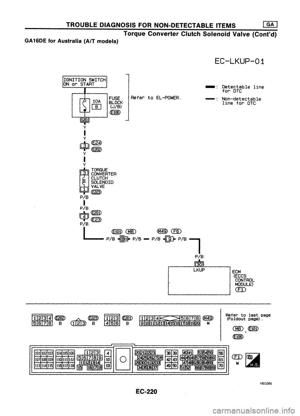
TROUBLEDIAGNOSIS FORNON-DETECTABLE ITEMS
em
Torque Converter ClutchSolenoid Valve(Cont'd)
GA16DE forAustralia (AIT models)
EC-LKUP-01
IGNITION SWITCH
ON
01"
START
10A
rn FUSE
BLOCK (JIB)
Refel"
toEL-POWER. _.
Detectable line
fol" DTC
-: Non-detectable
line fol"DTC
U
Q
j
6
11
y
I
y
$=
y
I
y
r=!::,
TORQUE
~3 CONVERTER
CLUTCH
SOLENOID
~~E
P/B
I
P/B
r=!::,
CE201)
1C4J1~
P/B
L
~CM8)
@@
PIS ~ PIS--PIS ~~ PiS~
P/B
Ii3tiJ
LKUP ECM
(ECCS
CONTROL
MODULE)
em
~~ ~~FmB1~
lIDIDZIID
B
w.g@)
B~ B
Refer
tolast page
(Foldout page).
101 102 103
107 108 109
113
114 115 104
105106
110
111
112
116
117
118
EC-220 HEC085
Page 940 of 1701
TROUBLEDIAGNOSIS FORNON-DETECTABLE ITEMS~
Torque Converter ClutchSolenoid Valve(Cont'd)
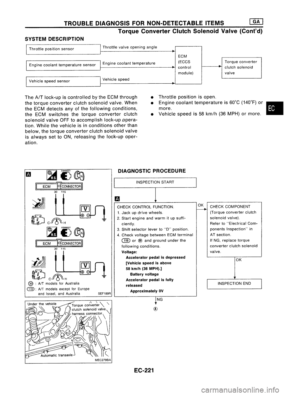
SYSTEM DESCRIPTION
Throttle position sensor Throttle
valveopening angle
Engine coolant temperature sensorEnginecoolant temperature ECM
(ECCS
control
module) Torque
converter
clutch solenoid
valve
Vehicle speedsensor Vehicle
speed
The
AfT
lock-up iscontrolled bythe ECM through
the torque converter clutchsolenoid valve.When
the ECM detects anyofthe following conditions,
the ECM switches thetorque converter clutch
solenoid valveOFFtoaccomplish lock-upDpera-
tion. While thevehicle isin conditions otherthan
below, thetorque converter clutchsolenoid valve
is always settoON, releasing thelock-up oper-
ation.
•
•
•
Throttle
position isopen .
Engine coolant temperature is60°C (140°F) or•
more.
Vehicle speedis58 kmfh (36MPH) ormore .
m ~
i3~
II
ECM
HCONNECTORII
30 115
ID
cf6~H
~i3~
II
ECM E
CONNECTOR
II
30 115
iIJ
ID
cf6~H
@> :
AIT
models forAustralia
@:
AlTmodels exceptforEurope
and Israel, andAustralia
SEF189RDIAGNOSTIC
PROCEDURE
INSPECTION START
CHECK CONTROL FUNCTION.
1. Jack updrive wheels.
2. Start engine andwarm itup suffi-
ciently.
3. Shift selector leverto"D" position.
4. Check voltage between ECMterminal
GID
or
@
and ground underthe
following conditions.
Voltage: Accelerator pedalisdepressed
[Vehicle speedisabove
58 km/h (36MPH).]
Battery voltage
Accelerator pedalisfully
released ApprOXimately OV
OK
CHECK COMPONENT
(Torque converter clutch
solenoid valve).
Refer to"Electrical Com-
ponents Inspection" in
AT section.
If NG, replace torque
converter clutchsolenoid
valve.
OK
INSPECTION END
MEC279BA NG
EC-221