immu NISSAN ALMERA N15 1995 Service Manual
[x] Cancel search | Manufacturer: NISSAN, Model Year: 1995, Model line: ALMERA N15, Model: NISSAN ALMERA N15 1995Pages: 1701, PDF Size: 82.27 MB
Page 393 of 1701
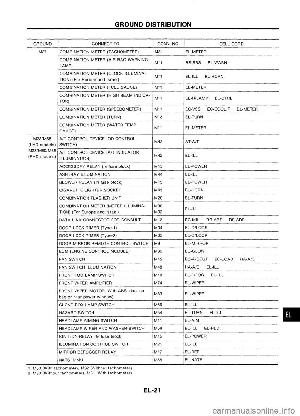
GROUNDDISTRIBUTION
GROUND CONNECT
TO CONN.NO.
CELLCORD
M27 COMBINATION
METER(TACHOMETER) M31EL-METER
COMBINATION METER(AIRBAG WARNING
M'1 RS-SRSEL-WARN
LAMP)
COMBINATION METER(CLOCK ILLUMINA-
M'1 EL-ILL
EL-HORN
TION) (ForEurope andIsrael)
COMBINATION METER(FUELGAUGE) M'1
EL-METER
COMBINATION METER(HIGHBEAM INDICA-
M'1 EL-H/LAMPEL-DTRL
TOR)
COMBINATION METER(SPEEDOMETER) M'1
EC-VSSEC-COOLIF EL-METER
COMBINATION METER(TURN) M'2EL-TURN
COMBINATION METER(WATER TEMP.
M'1 EL-METER
GAUGE)
.
M28/M68
A/T
CONTROL DEVICE(ODCONTROL
(LHD models)
SWITCH) M42
AT-A/T
M28/M60/M68
A/T
CONTROL DEVICE
(A/T
INDICATOR
(RHD models)
ILLUMINATION) M42
EL-ILL
ACCESSORY RELAY(Infuse block) M15
EL-POWER
ASHTRAY ILLUMINATION M44
EL-ILL
BLOWER RELAY(Infuse block) M15
EL-POWER
CIGARETTE LIGHTERSOCKET M43
EL-HORN
COMBINATION FLASHERUNIT M20EL-TURN
COMBINATION METER(METER ILLUMINA- M30
TION) (ForEurope andIsrael) M32EL-ILL
DATA LINKCONNECTOR FORCONSULT M13
EC-MILBR-ABS RS-SRS
DOOR LOCKTIMER (Type-1) M34
EL-D/LOCK
DOOR LOCKTIMER (Type-2) M35EL-D/LOCK
DOOR MIRROR REMOTE CONTROL SWITCHM9 EL-MIRROR
ECM (ENGINE CONTROL MODULE) M39EC-GLOW
FAN SWITCH M45
EC-A/CCUT
EC-LOADHA-A/C
FAN SWITCH ILLUMINATION M48HA-A/C
EL-ILL
FRONT FOGLAMP SWITCH M10EL-F/FOG
EL-ILL
FRONT WIPERAMPLIFIER M74
EL-WIPER
FRONT WIPERMOTOR (WithASS,dualair
M83 EL-WIPER
bag orrear power window)
GLOVE BOXLAMP SWITCH M66EL-ILL
HAZARD SWITCH M54
EL-TURN
EL-ILL
HEADLAMP AIMINGSWITCH M11EL-AIM
HEADLAMP WIPERANDWASHER SWITCH M56 EL-ILL
EL-HLC
IGNITION RELAY(Infuse block) M15EL-POWER
ILLUMINATION CONTROLSWITCH M21
EL-ILL
MIRROR DEFOGGER RELAY M17
EL-DEF
NATS IMMU M36EL-NATS
'1: M30 (With tachometer), M32(Without tachometer)
'2: M30 (Without tachometer), M31(With tachometer)
EL-21
•
Page 510 of 1701
![NISSAN ALMERA N15 1995 Service Manual WARNINGLAMPSANDBUZZER
Warning Lamps/Schematic
>-
[[
W
f-
f-
<I:
CD
w
(f)
:J
l.L
UG
NATS
SECURITY
INDICATOR
NATSIMMU
ABS ABS
CONTROL
UNIT
OIL OILPRESSURE SWITCH
FUEL
FUELTANKGAUGE UNIT
WAS](/img/5/57349/w960_57349-509.png "NISSAN ALMERA N15 1995 Service Manual WARNINGLAMPSANDBUZZER
Warning Lamps/Schematic
>-
[[
W
f-
f-
<I:
CD
w
(f)
:J
l.L
UG
NATS
SECURITY
INDICATOR
NATSIMMU
ABS ABS
CONTROL
UNIT
OIL OILPRESSURE SWITCH
FUEL
FUELTANKGAUGE UNIT
WAS")
WARNINGLAMPSANDBUZZER
Warning Lamps/Schematic
>-
[[
W
f-
f-
CD
w
(f)
:J
l.L
UG
NATS
SECURITY
INDICATOR
NATSIMMU
ABS ABS
CONTROL
UNIT
OIL OILPRESSURE SWITCH
FUEL
FUELTANKGAUGE UNIT
WASHER
WASHERFLUIDLEVELSWITCH
DOOR
FRONTDOORSWITCH
(Driver's side)
FRONT DOORSWITCH
(Passenger side)
REAR ODOR SWITCH LH
ALTERNATOR PARKING
BRAKESWITCH
FUEL FILTER SWITCH
=
BRAKE
FLUIDLEVEL SWITCH
REAR
ODORSWITCH RH
=
WARNING
BUZZER
UNIT
=
ECM (ECCS
CONTROL
MODULE)
ECM
(ENGINE
CONTROL
MODULE)
I
U
f- W
H (f)
3:f-
:J
(f)[[
l.L
Zf-
O(f)
H
f-L
HO
Z
BELT
C!JZ
HO
BRAKE
Q)
(I)
D.
rl
0
Q)
L
D
::J
0
W
E
L
C
0
ro
""-
D
Q)
(I)
(f)
rl
Q)
ro
D
D
'M
C
0
rl
ro
E
ro
L
~
Q) Q)
.....
u
C C
(I)
ro
.M
Q)
.M
ro
::J
.0
OJ
C
OJ
.M
c
.M
C
rl
U
Q)
OJ
Q)
ro
L
+'
C
L
0
ro
Q) Q) Q)
.....
""-
I
C C
(I)
GLOW
.M
rl
.
M
::J
.....
L
rl
Q)
rl
0
0
(I)
0
Q)
0
(I)
Q)
(I)
L
u
D
ro
.M
ro
0
x
I
C!J
0
C!J
l.L
W
lD
MALFUNCTION
@@~@@@
INDICATOR
AIRBAG
AIRBAG
DIAGNOSIS
SENSOR
UNIT
HEL082
EL-138
Page 511 of 1701
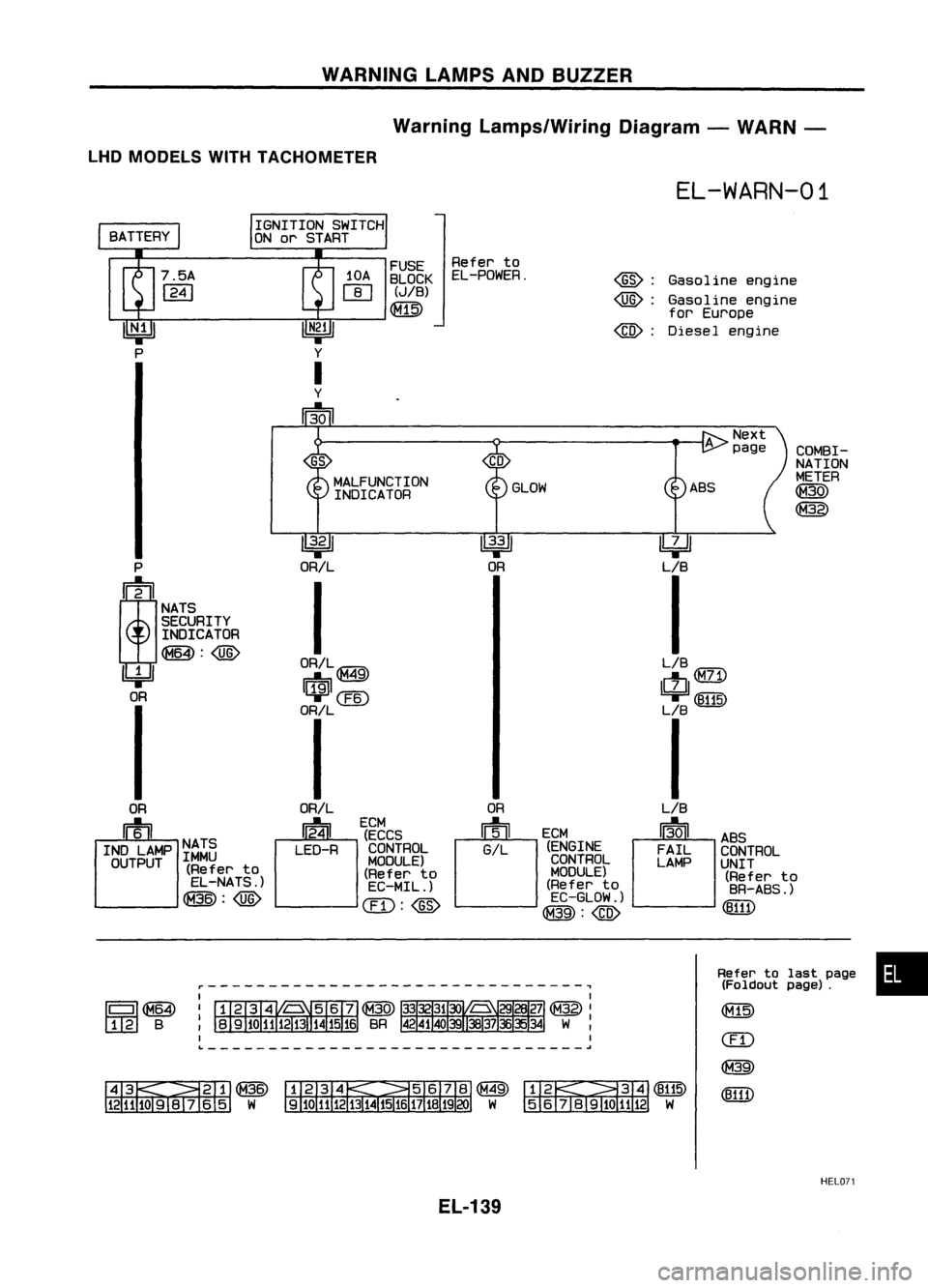
WARNINGLAMPSANDBUZZER
Warning Lamps/Wiring Diagram-WARN -
LHD MODELS WITHTACHOMETER
EL-WARN-01
Gasoline engine
Gasoline engine
for Europe
Diesel engine
@:
@):
@:
FUSE
Referto
10A BLOCK EL-POWER.
rn
(JIB)
Qill)
IGNITION
SWITCH
ON orSTART
COMBI-
GS
NATION
MALFUNCTION METER
INDICATOR GLOW
ABS
~
@)
~ ~~
P ORIL OR
LIB
;
I
I
NATS
SECURITY
INDICATOR
~:@)
ORIL@ LIB
IbjJ
rrf9il
49
ctJ
(M71)
OR
~@
'T
(8115)
ORIL LB
I I
OR ORIL OR
LIB
m
~
ECM
[~JCM
13-01
u'ECCS
ABS
INO LAMP NATS
LEO-RCONTROL GIL
(ENGINE
FAILCONTROL
OUTPUT IMMU
MODULE)CONTROL
LAMPUNIT
(Refer to
(Referto MODULE)
(Referto
EL-NATS.) EC-MIL.) (Refer
to
BR-ABS.)
~:@)
CIT):@
EC-GLOW.)
(8111)
@:@)
r-------------------------------,
IIIII~
1 2 B
~~@
1211J09lv 6
5
W
Refer
tolast page •
(Foldout page).
&~~
5
6j819101112 W
HELD?1
EL-139
Page 515 of 1701
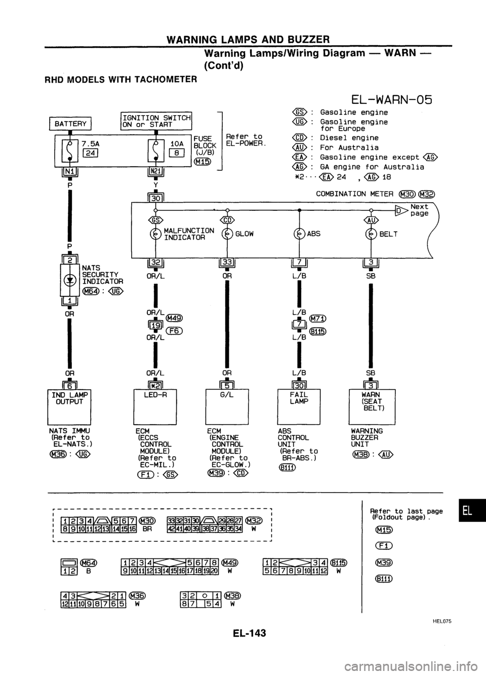
WARNINGLAMPSANDBUZZER
Warning Lamps/Wiring Diagram-WARN -
(Conl'd)
RHD MODELS WITHTACHOMETER
•
Refer
tolast page
(Foldout page).
(f1lli)
(ED
@
(8111)
WARNING
BUZZER
UNIT
@:@
~
SB
SB
u1il
r
WARN
(SEAT BELT)
EL-WARN-05
~: Gasoline engine
~: Gasoline engine
for Europe
~: Diesel engine
~: ForAustralia
~: Gasoline engineexcept~
~: GAengine forAustralia
*2"'@24 ,~1B
COMSINA TIONMETER
@)
@)
~~
J8191Q
1112
W
FUSE
Referto
BLOCK EL-POWER.
(JIB)
1 2 B
r---------------------------------,
GS
MALFUNCTION GLOWASS
INDICATOR
P
!
~
~
~
NATS
SECURITY ORIL OR
LIB
INDICATOR
I
I
~:@
'4=Jl
OR ORIL~ LIB
QQD
I$I@
ctl
71
I,
I
ORIL L
B
I I
OR ORILOR
LIB
n=til
0
U
13.0
I
IND LAMP LED-R
GILFAIL
OUTPUT LAMP
NATS IMMU
ECM ECM
ABS
(Refer to
(ECCS (ENGINECONTROL
EL-NATS.) CONTROLCONTROL
UNIT
@:~
MODULE)
MODULE)(Refer
to
(Refer to (Refer
to BR-ABS.)
EC-MIL.) EC-GLOW.)
(8111)
@: ~ @:@
~~@
12111091V
65 W
~@
~W
HEL075
EL-143
Page 519 of 1701

WARNINGLAMPSANDBUZZER
Warning Lamps/Wiring Diagram-WARN -
(Cont'd)
WITHOUT TACHOMETER
EL-WARN-09
FUELTANK
GAUGE UNIT
LOW (818)
HIGH
r.n
n
~ 888
B
i.Jl
FUEL
:
LHDmodels
@:
RHOmodels
~
G/R
I
1>
G/R ~ G/R~
1c!J1
@
1$1
(@
G/R G/R
~O~
I
G/R
m
OIL
LOW PRESSURE
SWITCH
HI~H-- ~
OIL
~
P/L
I
~01>
P
IL
f'UCi"\
P/L
f'UCi"\
~~ ~~
III7FII IlJdjl
T"' ~
'9F
(El0n
P/L P/L
t...oJ>
I
P/L~
c!J1illI
~(E202)
P/L
m
FUSE
Referto
8LOCK EL-POWER.
(J/8)
~
MALFUNCTION INDICATOR
~
ORIL
I
ORIL
Illii'n\
1i1'9il~
~@
ORIL
ORIL
0
24
LEO
RECM (ECCS
- CONTROL
MODULE) (Refer to
EC-MIL.)
ill)
P
;
NATS
SECULITY
INDICATOR
~
4=Jl
OR
OR
IFh
INO LAMP NATSIMMU
OUTPUT (Referto
EL-NATS.)
@>
L- __ --'
~-------------------------------~
~~@
5 6j819iO 1112W
Refer
tolast page •
(Foldout page).
CHID
(E10!)
ill)
IIIII~
128
~~@
l21U091V 65 W ~(E202)
rn::rn:rz::tm
8
([j])
<:lliTI)
GY
HEL079
EL-147
Page 619 of 1701
NATS(Nissan Anti-Theft System)
System Description
NATS V2.0forNissan modelN15hasthefollowing immobiliser functions:
• Since onlyNATS ignition keys,whose IDnos. have been registered intotheECM andIMMU ofNATS,
allow theengine torun, operation ofastolen vehicle withoutaNATS registered keyisprevented by
NATS.
That isto say, NATS V2.0willimmobilize theengine ifsomeone triestostart itwithout theregis-
tered keyofNATS V2.0.
• Both ofthe originally suppliedignitionkeyIDshave been NATS registered.
If requested bythe vehicle owner,amaximum offour keyIDscan beregistered intotheNATS com-
ponents.
• The NATS security indicator (NATSsecurity ind.)blinks whentheignition switchisin "OFF" or
"ACC" position. Therefore, NATSwarns outsiders thatthevehicle isequipped withtheanti-theft
system.
• When NATSdetects trouble, themalfunction indicatorlamp(MIL) blinks.
• NATS trouble diagnoses, systeminitialisation andadditional registration ofother NATS ignition key
IDs must becarried outusing CONSULT hardwareandCONSULT NATSsoftware.
When NATS initialisation hasbeen completed, theIDofthe inserted ignitionkeyisautomatically
NATS registered. Then,ifnecessary, additionalregistration ofother NATS ignition keyIDscan be
carried out.
Regarding theprocedures ofNATS initialisation andNATS ignition keyIDregistration, refertoCON-
SUL Toperation manual,NATSV2.0.
• When diagnosing NATSV2.0using CONSULT, adapterandadapter harness forNATS V1.0arenot
necessary, althoughadirect DDLcable connection betweenCONSULT andDOL connector is
required.
• When servicing amalfunction ofthe NATS V2.0(indicated byflashing ofMalfunction IndicatorLamp)
or registering anotherNATSignition keyIDno., itmay benecessary tore-register originalkeyiden-
tification. Therefore, besure toreceive allkeys from vehicle owner.
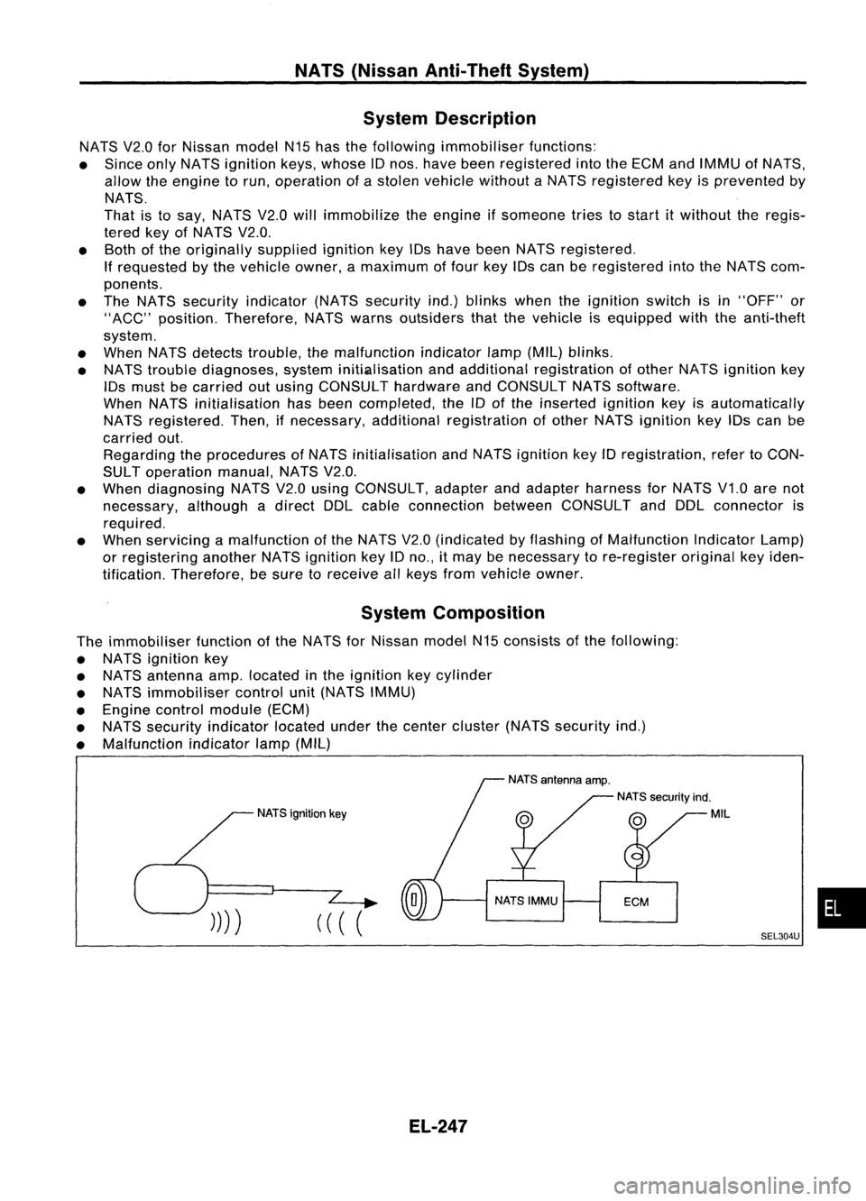
System Composition
The immobiliser functionofthe NATS forNissan modelN15consists ofthe following:
• NATS ignition key
• NATS antenna amp.located inthe ignition keycylinder
• NATS immobiliser controlunit(NATS IMMU)
• Engine control module (ECM)
• NATS security indicator locatedunderthecenter cluster (NATSsecurity ind.)
• Malfunction indicatorlamp(MIL)
NATS ignition key
(
((
(
El-247
SEL304U
•
Page 621 of 1701
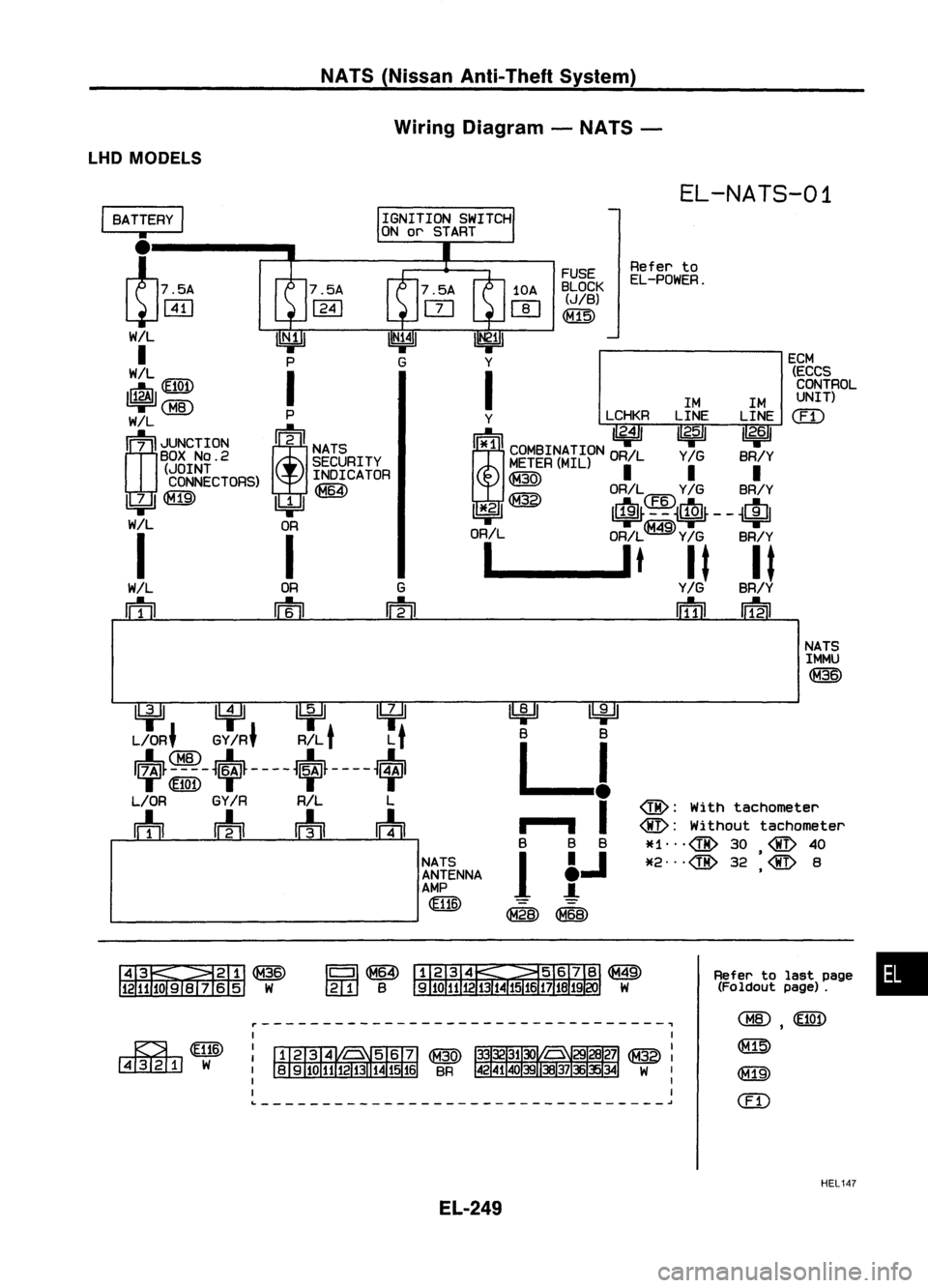
NATS(Nissan Anti-Theft System)
Wiring Diagram -NATS -
LHD MODELS
EL-NATS-01
ECM(ECCSCONTROL
UNIT)
em
Refer
to
EL-POWER.
FUSE
BLOCK
(JIB)
~
1M1M
Y LCHKRLINELINE
!i*1ll
"2.4/
I~ I 1/
2•6
11
i
COMBINATION ORILY
IG
BR/Y
M~~ER(MIL)
II I
~ OR/L
Y/G
BR/Y
11*.21 ~ It~~4~~~$~--
~Ifll
OR/L OR/L
Y/G
BR/Y
1 __
lt
It It
Y/G
BR/Y
IiTIil
IDil
G
m
OR
m
I
BATTERY
I
•
l75A
~WJ
W/L
I
WIL
~(fI@
~
rn;
I
JUNCTION
BOX
NO.2
(JOINT
CONNECTORS)
~
I
WIL
rn
NATSIMMU
~
~ lifll
U:¥~
L/OR' GY
IR'
R/L
t
L
t
~~-~~~----~~~----~
L/OR GY
IR
R/L L
m
wh
rrh
m
NATSANTENNA
AMP
~
~
B B
LJ
..
,- .., I
B BB
1
f.J
~~
@:
With tachometer
@:
Without tachometer
*1",@ 30
@
40
•
*2",@ 32
@
8
,
&~~
1211JOSIV 65 W
Refer
tolast page •
(Foldout page).
~WID
~W
r---------------------------------~
L ~
,
~
@])
em
HEL147
EL-249
Page 625 of 1701
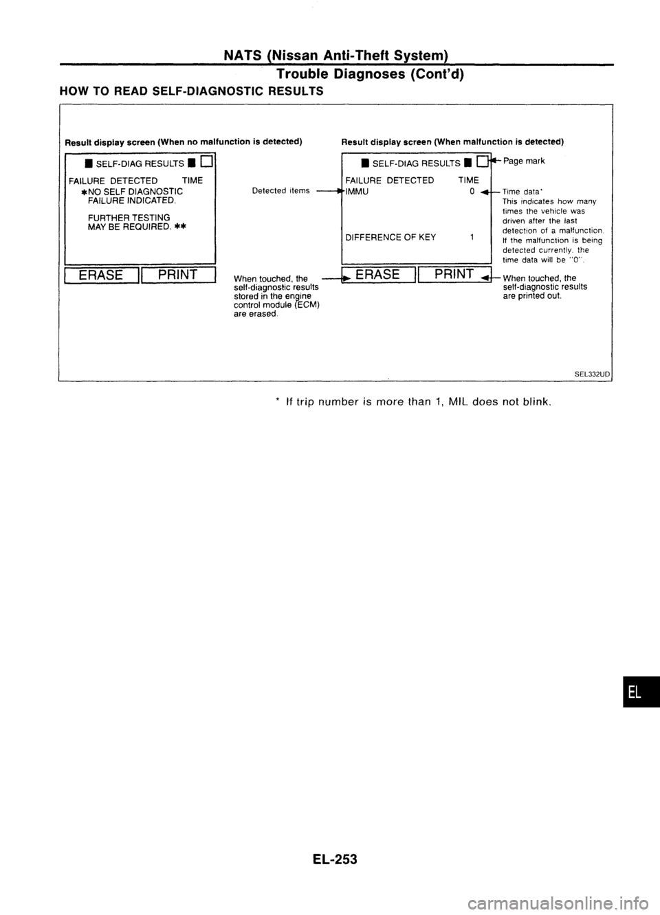
NATS(Nissan Anti-Theft System)
Trouble Diagnoses (Cont'd)
HOW TOREAD SELF-DIAGNOSTIC RESULTS
Resultdisplay screen(Whenmalfunction isdetected)
When touched, the
--l;
ERASE "PRINT
sell-diagnostic results
stored inthe engine
control module (ECM)
are erased. Page
mark
Time data'
This indicates howmany
times thevehicle was
driven afterthelast
detection ofamalfunction
If the malfunction isbeing
detected currently. the
time datawillbe"0".
;J-
When touched, the
self-diagnostic results
are printed out.
DIFFERENCE
OFKEY
•
SELF-DIAG RESULTS.
FAILURE DETECTED
IMMU
Detected
items
FURTHER TESTING
MAY BEREQUIRED.
**
ERASE "PRINT
Result
display screen(Whennomalfunction isdetected)
• SELF-DIAG RESULTS. D
FAILURE DETECTED TIME
*NO SELF DIAGNOSTIC
FAILURE INDICATED.
SEL332UD
*
Iftrip number ismore than1,MIL does notblink .
•
EL-253
Page 626 of 1701
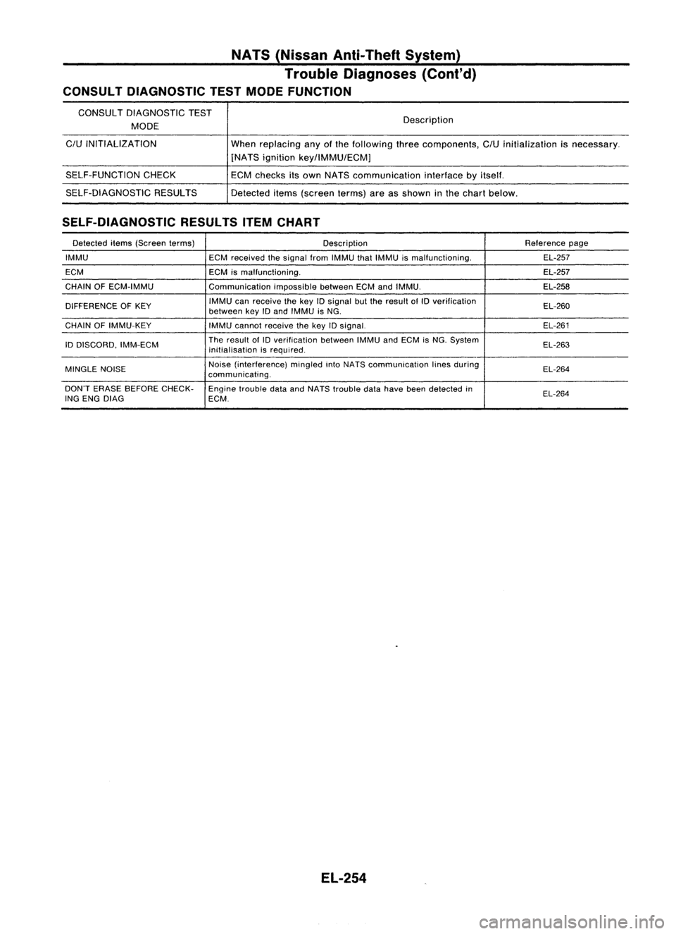
NATS(Nissan Anti-Theft System)
Trouble Diagnoses (Cont'd)
CONSULT DIAGNOSTIC TESTMODE FUNCTION
CONSULT DIAGNOSTIC TEST
MODE
C/U
INITIALIZATION
SELF-FUNCTION CHECK
SELF-DIAGNOSTIC RESULTS Description
When replacing anyofthe following threecomponents,
C/U
initialization isnecessary.
[NATS ignition key/lMMU/ECMj
ECM checks itsown NATS communication interfacebyitself.
Detected items(screen terms)areasshown inthe chart below.
SELF-DIAGNOSTIC RESULTSITEMCHART
Detected items(Screen terms) Description Reference
page
IMMU ECMreceived thesignal fromIMMU thatIMMU ismalfunctioning. EL-257
ECM ECMismalfunctioning. EL-257
CHAIN OFECM-IMMU CommunicationimpossiblebetweenECMandIMMU. EL-258
DIFFERENCE OFKEY IMMU
canreceive thekey
10
signal butthe result ofID verification
EL-260
between keyIDand IMMU isNG.
CHAIN OFIMMU-KEY
IMMUcannot receive thekey IDsignal. EL-261
ID DISCORD, IMM-ECM The
result of
10
verification betweenIMMUandECM isNG. System
EL-263
initialisation isrequired.
MINGLE NOISE Noise
(interference) mingledintoNATS communication linesduring
EL-264
communicating.
DON'T ERASE BEFORE CHECK-
Enginetrouble dataandNATS trouble datahave beendetected in
EL-264
ING ENG DIAG ECM.
EL-254
Page 627 of 1701
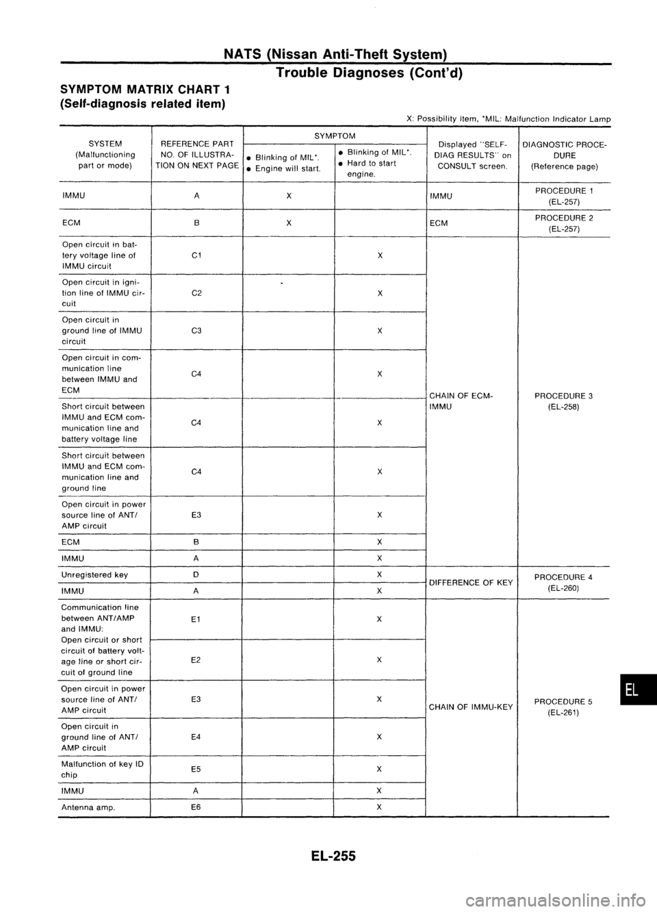
NATS(Nissan Anti-Theft System)
Trouble Diagnoses (Cont'd)
SYMPTOM MATRIXCHART1
(Self-diagnosis relateditem)
X:Possibility item.'MIL: Malfunction IndicatorLamp
SYMPTOM
SYSTEM REFERENCEPART
Displayed"SELF-
DIAGNOSTIC PROCE-
(Malfunctioning NO.OFILLUSTRA-
•Blinking ofMIL'. •
Blinking ofMIL'.
DIAGRESULTS" on
DURE
part ormode) TIONONNEXT PAGE
•Engine willstart. •
Hard tostart
CONSULTscreen.
(Referencepage)
engine.
IMMU A
X IMMUPROCEDURE
1
(EL-257)
ECM BX
ECMPROCEDURE
2
(EL-257)
Open circuit inbat-
tery voltage lineof C1
X
IMMU circuit
Open circuit inigni-
.
tion lineofIMMU cir- C2
X
cuit
Open circuit in
ground lineofIMMU
C3 X
circuit
Open circuit incom-
munication line
C4
X
between IMMUand
ECM CHAINOFECM-
PROCEDURE3
Short circuit between IMMU
(EL-258)
IMMU andECM com-
C4
X
munication lineand
battery voltage line
Short circuit between
IMMU andECM com-
C4 X
munication lineand
ground line
Open circuit inpower
source lineofANTI E3
X
AMP circuit
ECM B X
IMMU A
X
Unregistered key 0 X
PROCEDURE4
DIFFERENCE OFKEY
IMMU A
X
(EL-260)
Communication line
between ANT
I
AMP
E1
X
and IMMU:
Open circuit orshort
circuit ofbattery volt-
age lineorshort cir- E2
X
cuit ofground line
Open circuit inpower
source lineofANTI E3
X
PROCEDURE5
AMP circuit CHAIN
OFIMMU-KEY
(EL-261)
Open circuit in
ground lineofANTI E4
X
AMP circuit
Malfunction ofkey 10
E5 X
chip
IMMU A
X
Antenna amp. E6
X
EL-255
•